Smart socket REDMOND SkyPort 100S
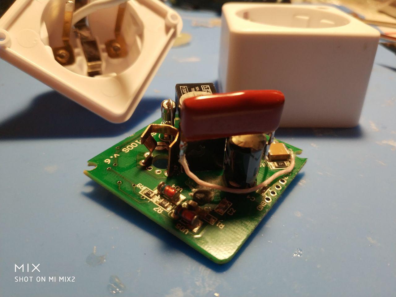
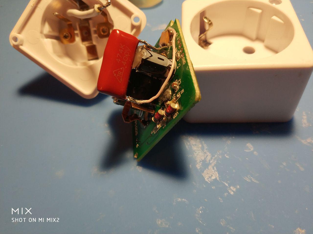
This is a continuation of my first article on the Redmond Smart Cap . In this article, we will talk about another Redmond device - Smart socket REDMOND SkyPort 100S. This device is also based on the nRF51822 chip, and as they say here, God himself ordered a try. So, this socket was purchased. The case is disassembled as easily as the base, access to the programming port is even more convenient. But looking ahead, I’ll say that everything is a little more complicated than it seemed to me at first. I did not ring the circuit of this outlet, because There are already a bunch of reviews on upgrading and modifying these outlets.

In one of the reviews I found a circuit, and this was limited. From the diagram it is clear that only 4 pins on the nRF51822 module are involved in the same way as in the smart base. The device has a clock button connected to pin p0.00, two LEDs, red is connected to pin p0.01, green is connected to pin p0.02. An electromagnetic relay at 10A is connected to pin p0.03. So, start the Arduino IDE and start to throw an instance:
#define BUTTON_PIN 0
#define RED_LED_PIN 1
#define GREEN_LED_PIN 2
#define RELAY_PIN 3
boolean iswitch = 0;
boolean flag_button = 0;
static uint32_t previousMillis;
//#define MY_DEBUG
#define MY_DISABLED_SERIAL
#define MY_RADIO_NRF5_ESB
//#define MY_NRF5_ESB_PA_LEVEL (NRF5_PA_LOW)
#define MY_NRF5_ESB_PA_LEVEL (NRF5_PA_MAX)
//#define MY_PASSIVE_NODE
#define MY_NODE_ID 201
#define MY_PARENT_NODE_ID 0
#define MY_PARENT_NODE_IS_STATIC
#define MY_TRANSPORT_UPLINK_CHECK_DISABLED
#define RELAY_ID 1
#include
MyMessage lMsg(RELAY_ID, V_STATUS);
void preHwInit() {
  pinMode(BUTTON_PIN, INPUT_PULLUP);
  pinMode(RED_LED_PIN, OUTPUT);
  pinMode(GREEN_LED_PIN, OUTPUT);
  pinMode(RELAY_PIN, OUTPUT);
}
void before()
{
  digitalWrite(RED_LED_PIN, HIGH);
}
void presentation()
{
  sendSketchInfo("REDMOND R nRF51", "1.0");
  wait(300);
  present(RELAY_ID, S_BINARY, "RELAY SWITCH");
  wait(300);
}
void setup()
{
  digitalWrite(RED_LED_PIN, LOW);
  wait(300);
  digitalWrite(GREEN_LED_PIN, HIGH);
  wait(200);
  digitalWrite(GREEN_LED_PIN, LOW);
  wait(200);
  digitalWrite(GREEN_LED_PIN, HIGH);
  wait(200);
  digitalWrite(GREEN_LED_PIN, LOW);
  wait(200);
  digitalWrite(GREEN_LED_PIN, HIGH);
  wait(200);
  digitalWrite(GREEN_LED_PIN, LOW);
  wait(500);
  send(lMsg.set(iswitch));
  wait(500);
}
void loop()
{
  if (digitalRead(BUTTON_PIN) == LOW && flag_button == 0) {
    flag_button = 1;
    previousMillis = millis();
    wait(20);
  }
  if (digitalRead(BUTTON_PIN) == LOW && flag_button == 1) {
    //что нибудь потом добавить, может быть
  }
  if (digitalRead(BUTTON_PIN) == HIGH && flag_button == 1) {
    if ((millis() - previousMillis > 0) && (millis() - previousMillis <= 3000)) {
      if (iswitch == 0) {
        digitalWrite(GREEN_LED_PIN, HIGH);
        wait(10);
      } else if (iswitch == 1) {
        digitalWrite(GREEN_LED_PIN, LOW);
        wait(10);
      }
      flag_button = 0;
      iswitch = !iswitch;
      digitalWrite(RELAY_PIN, iswitch);
      wait(1500);
      send(lMsg.set(iswitch));
    }
    if (millis() - previousMillis > 3000)
    {
      flag_button = 0;
    }
  }
}
void receive(const MyMessage & message) {
  if (message.type == V_STATUS) {
    if (message.sensor == RELAY_ID) {
      if (mGetCommand(message) == 1) {
        if (message.isAck()) {
          //AckG = 1;
        } else {
          wait(50);
          if (iswitch == 0) {
            digitalWrite(GREEN_LED_PIN, HIGH);
          }else
          if (iswitch == 1) {
            digitalWrite(GREEN_LED_PIN, LOW);
          }
          iswitch = !iswitch;
          wait(10);
          digitalWrite(RELAY_PIN, iswitch);
          wait(1500);
          send(lMsg.set(iswitch));
        }
      }
      if (mGetCommand(message) == 2) {
      }
    }
  }
}
As you can see, the code is small and fairly simple, thanks for that to the Mysensors community.
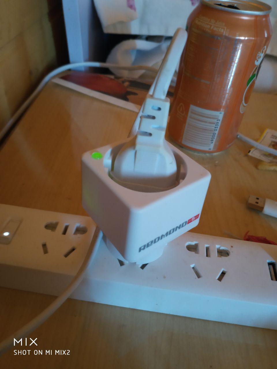
As the code was finished, I connected the programmer to the device and reflashed it. Connecting the programmer to the outlet is very simple, in my case I took two ordinary output resistors, bit off the wire with wire cutters, made hooks from the wire, bent it, inserted these hooks into the programmer wires and “hooked” to the outlet, the video shows how I do it . It's time to test what happened. I inserted a smart socket into a socket :), opened the Majordomo, everything is fine, the socket was already present on the Maysensors network. I send the first command to turn on and ... reboot :) ... unexpected turn. The first thing that came to mind was a power drawdown while the relay was on. He changed the program, removed the inclusion of the LED when the relay is turned on, in order to reduce consumption. And it worked, the socket stopped rebooting when the relay was turned off. ... But not for long :). And so it became clear that the module lacked power. The circuit of the transformerless power supply is designed so that it would be enough only to work in BLE mode. Mysensors also uses a different mode of the 2.4 GHz radio module (compatibility with RF24 - ANT). So we have a deficit of about 10mA. Having discussed the problem in our chat, Mysensors settled on the decision to add a ballast capacitor, since this is a very simple manipulation, which is what you need to repeat.
Reassembling the outlet, he began to test a little excitedly. The development was now excellent. I rewrote the logic of the program back, added another #define MY_NRF5_ESB_PA_LEVEL (NRF5_PA_MAX), that is, I "cut" the radio at full power (yes, it is very simple with Mysensors ). ... It works. No mistakes. No reboots. This is victory :)
But this manufacturer also has other devices on the nRF51822 - a smoke sensor, a motion sensor, a gas sensor, thermal converters, fans, humidifiers, cleaners, kettles ...;)
A telegram chat of our community, where they will always help to install libraries, support for boards, explain how in half an hour to build a network of sensors on arduins without a headache - https://t.me/mysensors_rus