Thermoacoustics. Generating electricity from sound using a speaker

Fig. 1. - Appearance of a 4-stage thermoacoustic engine with a traveling wave
In previous articles I wrote about how to build a Stirling engine without pistons, that is, how to build a ring thermoacoustic engine with a traveling wave 1 article , 2 article , 3 article .
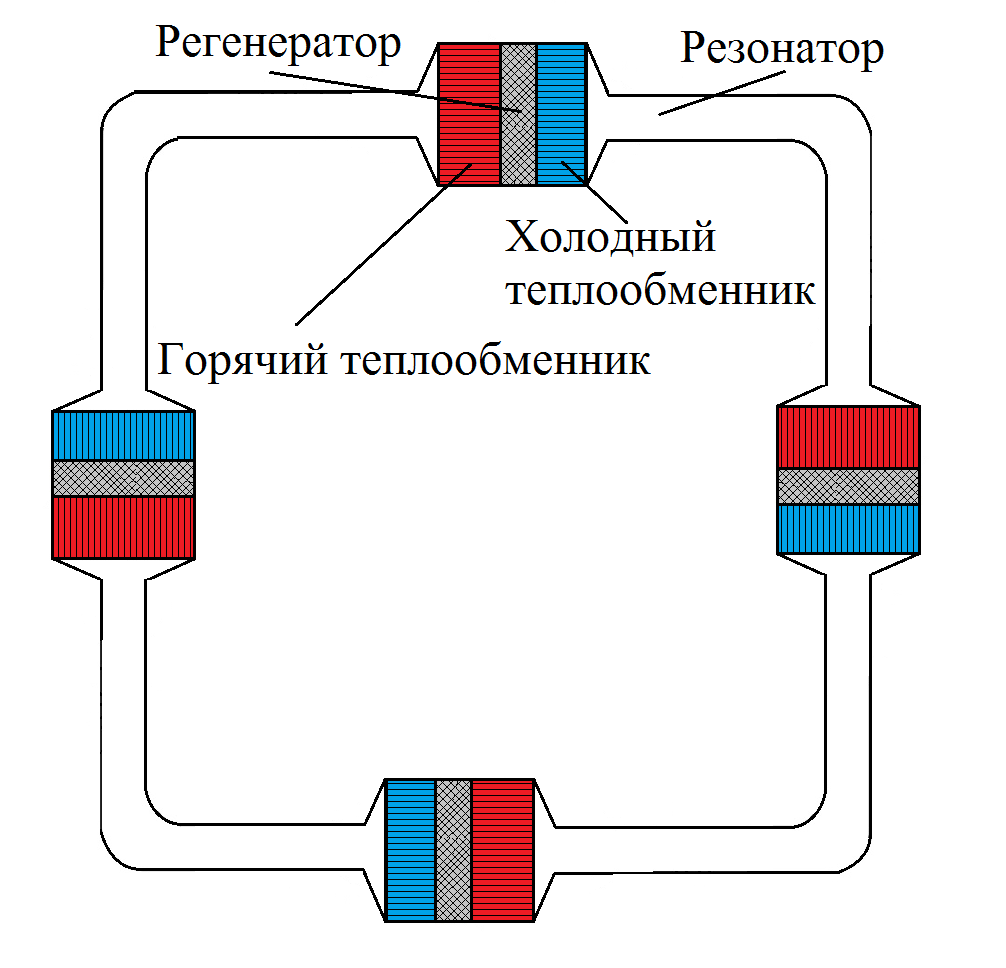
Fig. 2. - Engine diagram The engine
consists of 4 absolutely identical blocks. Each of the blocks consists of a heat exchanger, consisting of a hot heat exchanger, a cold heat exchanger and a regenerator between them. The heat exchanger is sometimes called the engine core. The entire heat exchanger in the housing is called the engine stage.
When the engine is running, an extremely high-intensity acoustic wave is present inside the entire annular casing. What is the typical distribution of pressure fluctuations, vibrational velocity and acoustic power inside? In order to find out, I simulated the processes occurring in the engine using a special program developed at the Los Alamos National Laboratory (that is, in the same place as the atomic bomb) called DeltaEC. Next are the graphs for the engine under load. That is, for such a case:
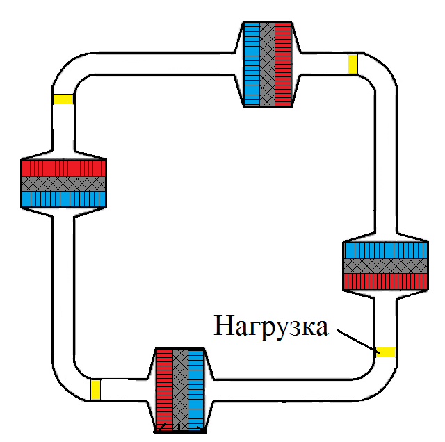
Fig. 3. - Engine under load In
cases where the engine has a load, even four loads that are located near hot heat exchangers.
The graph of the distribution of the amplitude of the pressure fluctuations in one of the four engine blocks looks like this:
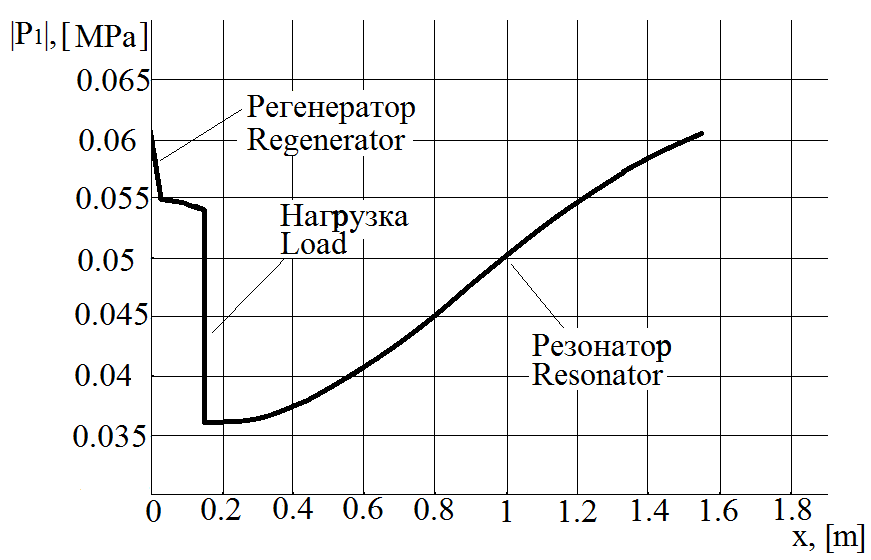
Fig. 4. - Distribution of the amplitude of pressure fluctuations along the length of one of the blocks
. One fourth of the engine is shown here. You can see that the graph goes up to a length of about 1.5 m - this is the length of one block. It turns out that the length of the entire annular engine casing is about 6 meters. In all blocks, all parameters are the same, so just consider one of them.
The heat exchanger on the graph is on the left, starting from zero on the horizontal axis. It is seen that in the regenerator, due to viscosity loss and reflection of part of the wave from it, the amplitude of pressure fluctuations decreases. Then comes the load, where the pressure decreases even more. Further, the pressure increases to the initial value in the resonator, due to a decrease in the vibrational velocity of the gas in the resonator
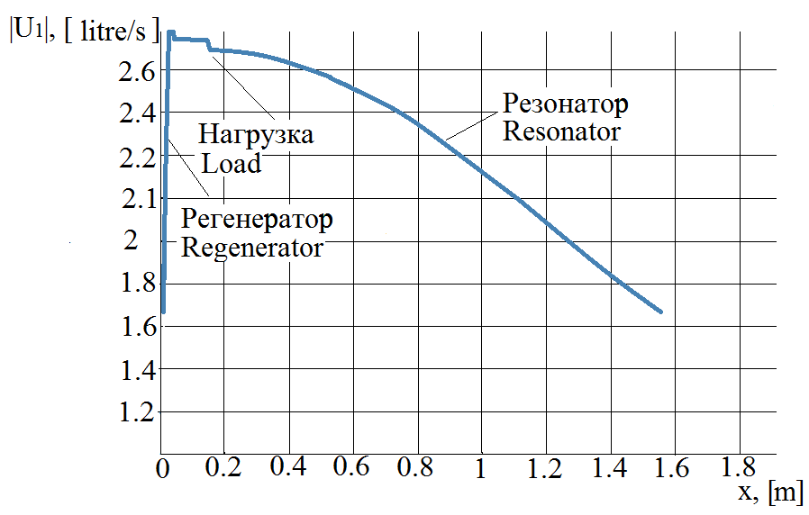
Fig. 5. - Distribution of the amplitude of the volumetric flow rate fluctuations along the length of the block
In thermoacoustics, it is customary in calculations to use not the vibrational velocity of the gas, but the volumetric flow fluctuations, that is, the vibrational velocity multiplied by the cross-sectional area of the housing. Fluctuations in volumetric flow rate are proportional to speed fluctuations with a constant cross-sectional area of the housing.
In fig. Figure 5 shows that a sharp increase, an abrupt increase in the amplitude of fluctuations in volumetric flow, occurs in the regenerator (about zero along the horizontal axis). Just this sharp increase in volumetric flow rate fluctuations or gas velocity fluctuations (to whom it is more convenient) is the thermoacoustic effect of amplification of an acoustic wave. The volumetric flow rate then decreases slightly, passing through the load, and then finally decreases to its original value, passing through the resonator. Due to this decrease in fluctuations in the volumetric flow rate in the resonator, an increase in pressure fluctuations in the resonator occurs, which was mentioned in the description of the previous graph.
What are these two graphs talking about? They say that in the whole engine, which is called a running wave engine, there has never been and never will be a purely running wave. A traveling wave in this engine is observed only in the area of the heat exchanger. That is, in the regenerator zone, the phase difference between the pressure and gas velocity fluctuations is about zero. In all other parts of the engine, the wave is far from running, but is a mixture of a traveling and standing wave.
What is also interesting here is that the thermoacoustic effect does not increase the amplitude of pressure fluctuations, but only increases the amplitude of fluctuations in the gas volumetric flow rate.
Now let's see how the power of an acoustic wave changes.
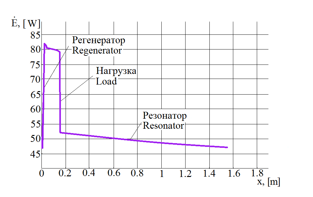
Fig. 6. - Distribution of wave power along the length of the block
It can be seen that in the regenerator the power increases abruptly due to the thermoacoustic effect, then a little power is lost when the wave passes to the load, then there is a sharp jump in power down, associated with the loss of energy at the load and further wave attenuation continues in the remainder of the resonator to its original value.
Let’s now think about how to determine the efficiency of the process.
In general, how to calculate the efficiency? It is necessary to divide the useful power by the consumed. With the expended power, everything is clear here - this is the input thermal power, the heating power of the engine. But what is considered useful acoustic power?
In fig. 6, the acoustic power reaches a maximum immediately after the regenerator and reaches a value of 82 W. It is this power that should be considered useful here? Not really. The useful acoustic power here - this is the increase in acoustic power in the regenerator, and a value of about 46 W relative to which the increase begins - can be called a reference level. Rather, even I would call a wave with a power of 46 W here - a reference wave, since it is precisely it that the engine regenerator amplifies. Then already this increase in power in the regenerator goes partially to the load, and partially dissipates, passing through the resonator. When designing the engine to achieve maximum efficiency of the system, you must try to make the power that is dissipated in the resonator much less than the power that is dissipated on the load,
From the above it follows that the acoustic efficiency of the engine will always be greater than the efficiency of the entire system with a load, since the power dissipated on the load is part of the increase in power in the regenerator.
So how do you convert the energy of sound into electricity?
With a Stirling engine with power generation, everything is clear. If there is a crankshaft, then a rotating electric generator can be attached to it. If the Stirling engine is resonant, then you can attach the magnet to the working piston and place it in the stator of the linear generator. But what to do in the case of a thermoacoustic engine? How to get electricity in an engine where there is no crankshaft or pistons? How to convert high-intensity acoustic energy to electrical? To date, two ways have been devised to do this.
The first way is to use linear converters.
Here is a video on my channel where I am experimenting with a linear converter:
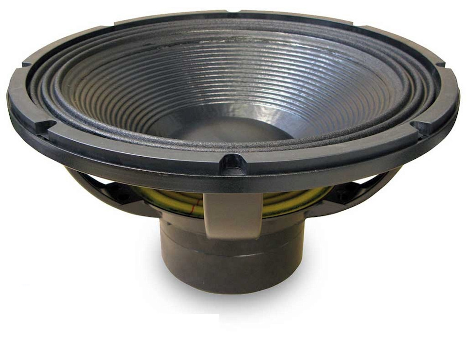
Fig. 7. - Woofer
An ordinary speaker is an example of a linear transducer. Usually, during operation, it converts electrical energy, which is supplied to it by the input into sound, that is, into acoustic energy. But it can very well work in the opposite direction and convert acoustic vibrations into electricity. Ordinary speakers are not designed for extremely high sound intensity as in thermoacoustic devices (160 - 180 dB.), Therefore, they have large energy losses associated with a low quality factor of the oscillatory system, a large absorption coefficient of the wave membrane due to its insufficient rigidity, and also insufficient the membrane’s free play does not allow the use of all available power. Therefore, they make special speakers - linear alternators, which by the principle of operation are no different from the speaker,
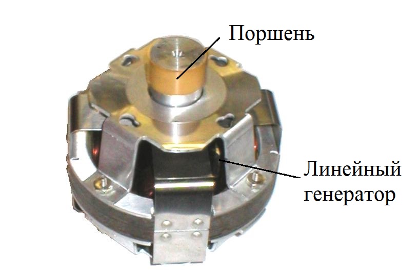
Fig. 8. - A linear alternator from Q-Drive, the
efficiency of converting acoustic energy into electrical energy using such a converter can reach 80%.
The second conversion method is to use a bi-directional turbine generator.
Sounds found in the everyday life of most people, such as speech, the sounds of passing cars, the barking of a dog, have a low intensity by the standards of thermoacoustics. The displacement of the gas from the equilibrium position in the acoustic wave of conversational speech is fractions of a millimeter, so that no one usually perceives a sound wave as a wind that changes its direction thousands of times per second, that is, changes direction with a frequency equal to the frequency of the wave. In thermoacoustics, when the intensity of oscillations reaches 180 decibels, the sound no longer even becomes a wind, which changes direction with great frequency, but rather a hurricane with a peak speed reaching 100 km / h. Therefore, a turbine can be used to convert this sound energy into electricity. In this video, I conducted interesting experiments on this topic,
It is immediately clear that the direction of rotation of the turbine rotor for thermoacoustics should not depend on the direction of flow of the incoming and outgoing turbines, otherwise the flow will accelerate the rotor for half of the oscillation period and slow down the second half of the period. There are two types of bi-directional turbines, the direction of rotation of which does not depend on the direction of flow. This is a Wales turbine, the rotor blades of which are aerodynamic profiles located across the incoming flow.
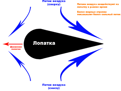
Fig. 9. - Wales turbine blade. The
aerodynamic profile deflects a large mass of incoming air in the same direction regardless of the direction of movement of the incoming air. The air impulse deviates all the time, in fig. 9 to the right, that means, according to Newton’s laws, the force acting on the shoulder blades should be directed to the left side. Newton’s laws in this case work properly and if you fix such blades around the circumference of the circle, and fix the circle on the shaft, the shaft will begin to rotate.
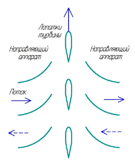
Fig. 10.– Wales turbine
design You can improve the design and add guide vanes that will increase the effect.
The second type of bi-directional turbines are the so-called impulse turbines. This video shows how such a turbine works:
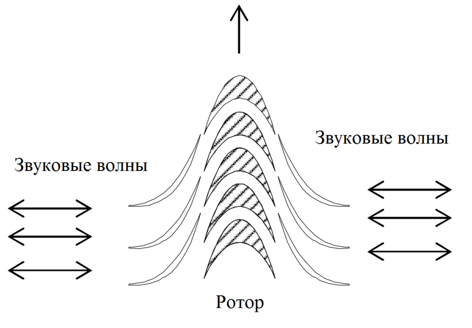
Fig. 11.– Diagram of a bi-directional impulse turbine An
impulse turbine operates more efficiently than a Wales turbine due to the more perfect shape of the rotor blades.
Experimental part
For the first experiments on generating electricity on my engine, I chose the simplest method and the most ineffective one - using an ordinary woofer.
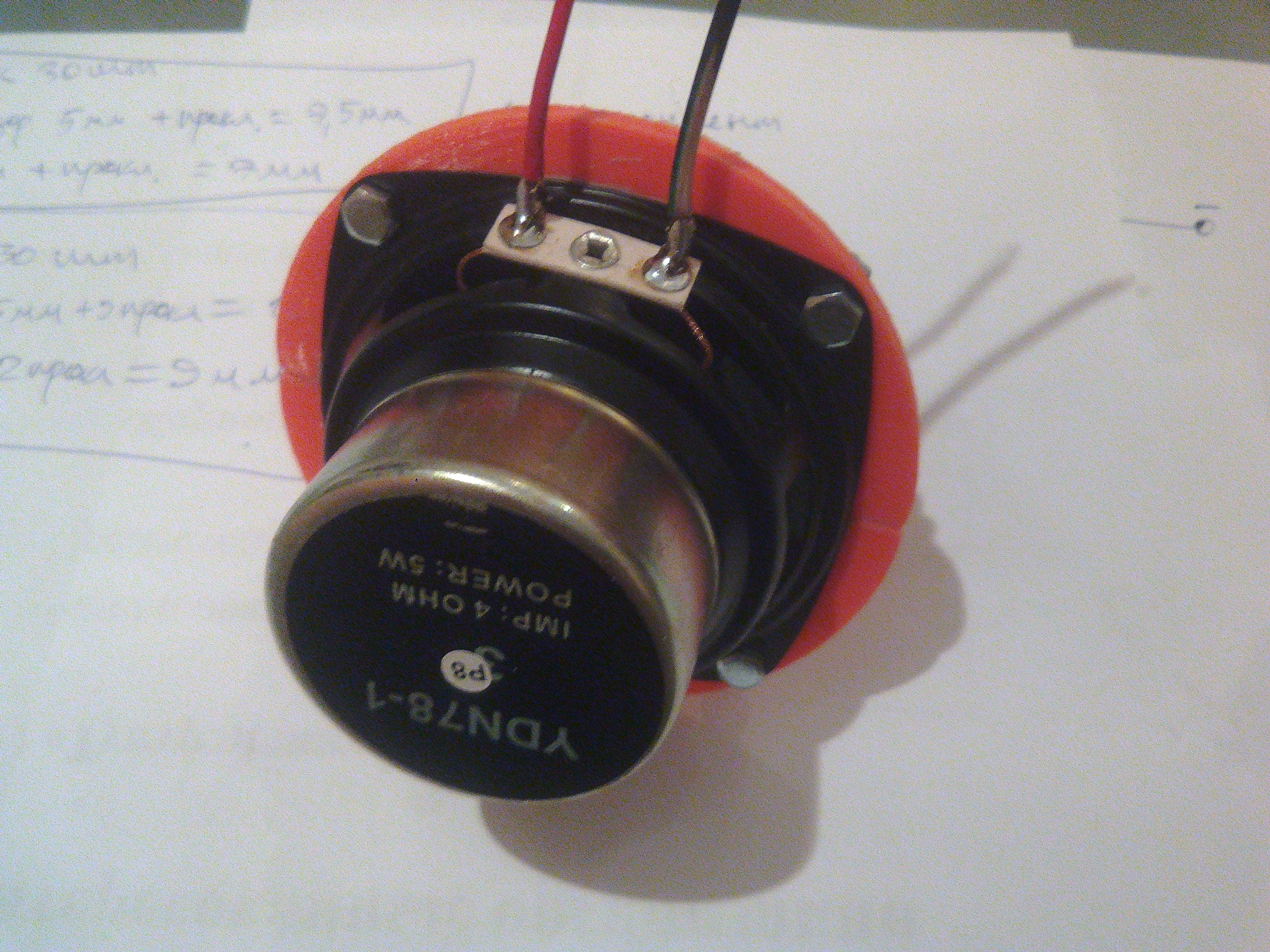
Fig. 12. - Linear converter from the speaker
Here in this video I talk about how I created and tried to configure the resulting home-made linear alternator:
I attached the speaker to the engine resonator through such an adapter that I printed on a 3D printer.
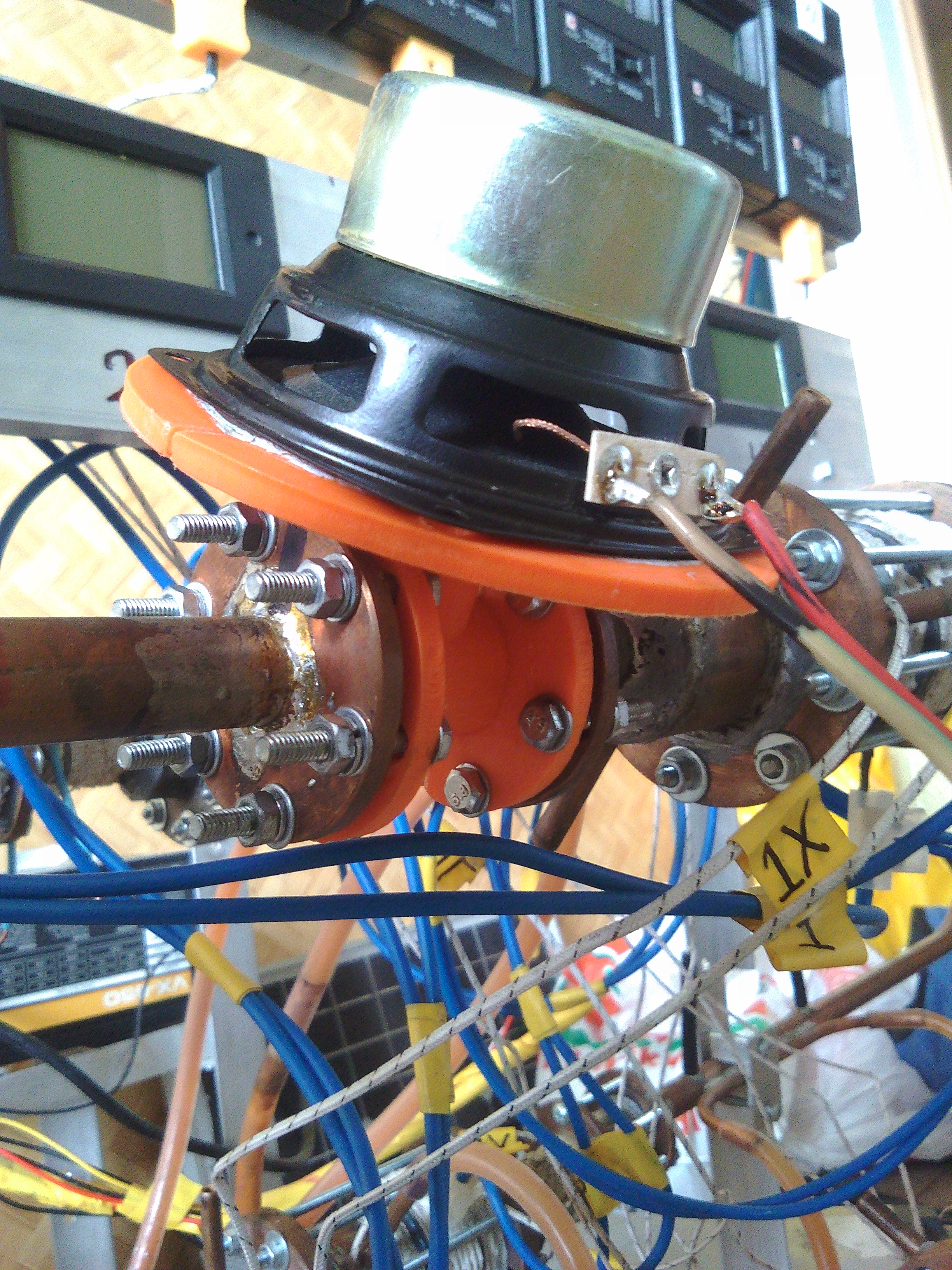
Fig. 13. -
Speaker connection Attached to the resonator from the side of the cold heat exchanger, so as not to melt the plastic adapter at high temperature and damage the speaker itself. Earlier, I measured the acoustic power of the engine. Power was about 10 watts. Naturally, only part of this power can be converted into electricity. Remembering Figure 6 - distribution of acoustic power, as a linear alternator, I chose the YDN-78-1 speaker with a maximum power of 2 times less than the acoustic power of the engine, namely - 5 watts.
The most difficult thing when using a linear alternator is to set up a system consisting of a speaker and an adapter for the resonant frequency of the engine itself. The difficulty is that the frequency of engine vibrations varies at different temperatures of heating of hot heat exchangers, that is, at different levels of heat input. And all because the more thermal power you bring, the greater the average temperature of the gas inside becomes and with increasing gas temperature, the speed of sound in the gas increases, and accordingly the oscillation frequency. At the same time, measurements made by Aster Thermoacoustics show that the output power of a linear converter strongly depends on the coincidence of its resonant frequency with the resonant frequency of the motor.
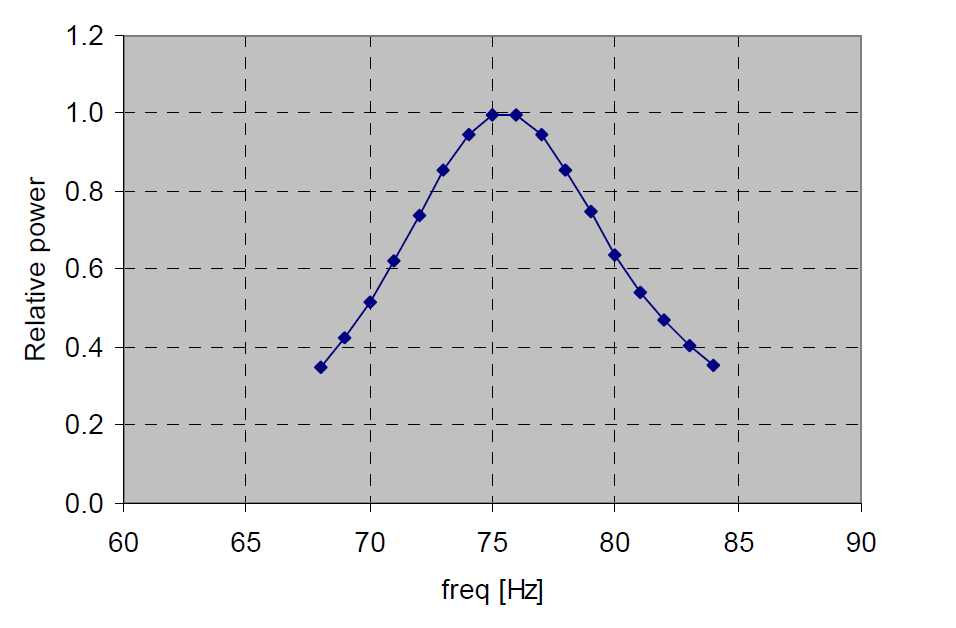
Fig. 14. The dependence of the relative output power on the resonant frequency of the motor
Experiments with my engine showed that increasing the temperature of hot heat exchangers from 120 degrees Celsius to 220 degrees, the oscillation frequency increases from 61 Hz to 64 Hz, that is, changes by 3 Hz. In fig. 14 - on the Aster Thermoacoustics graph the motor frequency is marked on the horizontal axis, and the output electric power of the linear converter divided by the maximum converter power in the entire frequency range along the vertical axis (this is the maximum value on the graph equal to one). In fig. 14 it is seen that when the resonant frequency of the motor deviates from the resonant frequency of the converter by 5 Hz, the output power decreases by a factor of 2. This means that a thermoacoustic generator with a linear alternator can operate efficiently only at a certain level of heat input.
So, the resonant frequency of my engine is 61 - 63 Hz. I did not find speakers with such a low resonant frequency (it is possible that they do not exist at all for such a small power). The resonant frequency of my speaker was originally 147 Hz. How did I measure it?
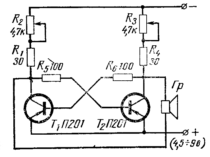
Fig. 15. - Scheme for determining the resonant frequency of the speaker.
I used the circuit from the journal "Radio" issue No. 4 of 1967, page 45. This is a circuit of a self-oscillating electric circuit in which there are no inductances or capacitances, therefore, as conceived, the oscillation frequency of such a circuit is determined by the oscillation frequency of the mechanical oscillatory system - the diaphragm of the speaker.
Then I reduced the speaker frequency to 61 Hz by sticking plasticine on the diaphragm. This increased the mass of the diaphragm and thus reduced the frequency.
After that, I inserted the tuned speaker into the orange adapter. what was my surprise when, instead of the oscillation frequency of 63 Hz, I found the oscillation frequency of 187 Hz, that is, three times more than expected. The 3rd harmonic was excited. Three wavelengths began to fit into the engine housing, and not one. In fact, non-fundamental harmonics are always present in the engine, just usually the thermoacoustic devices operate at the first harmonic, that is, at the fundamental frequency, and the contribution of the other harmonics is negligible. I was very surprised by the effect of the 3rd harmonic excitation in this experiment with the speaker, and I began to think how it happened. I came to the conclusion that this effect occurs because the speaker is built into the resonator of the engine through the adapter and it is necessary to consider the resonant frequency of the speaker not separately, and the dynamics together with the adapter. The adapter greatly increases the resonant frequency of the entire ligament. Therefore, in order to achieve operation at the fundamental frequency of 63 Hz, it is necessary to lower the resonant frequency of the speaker even more.
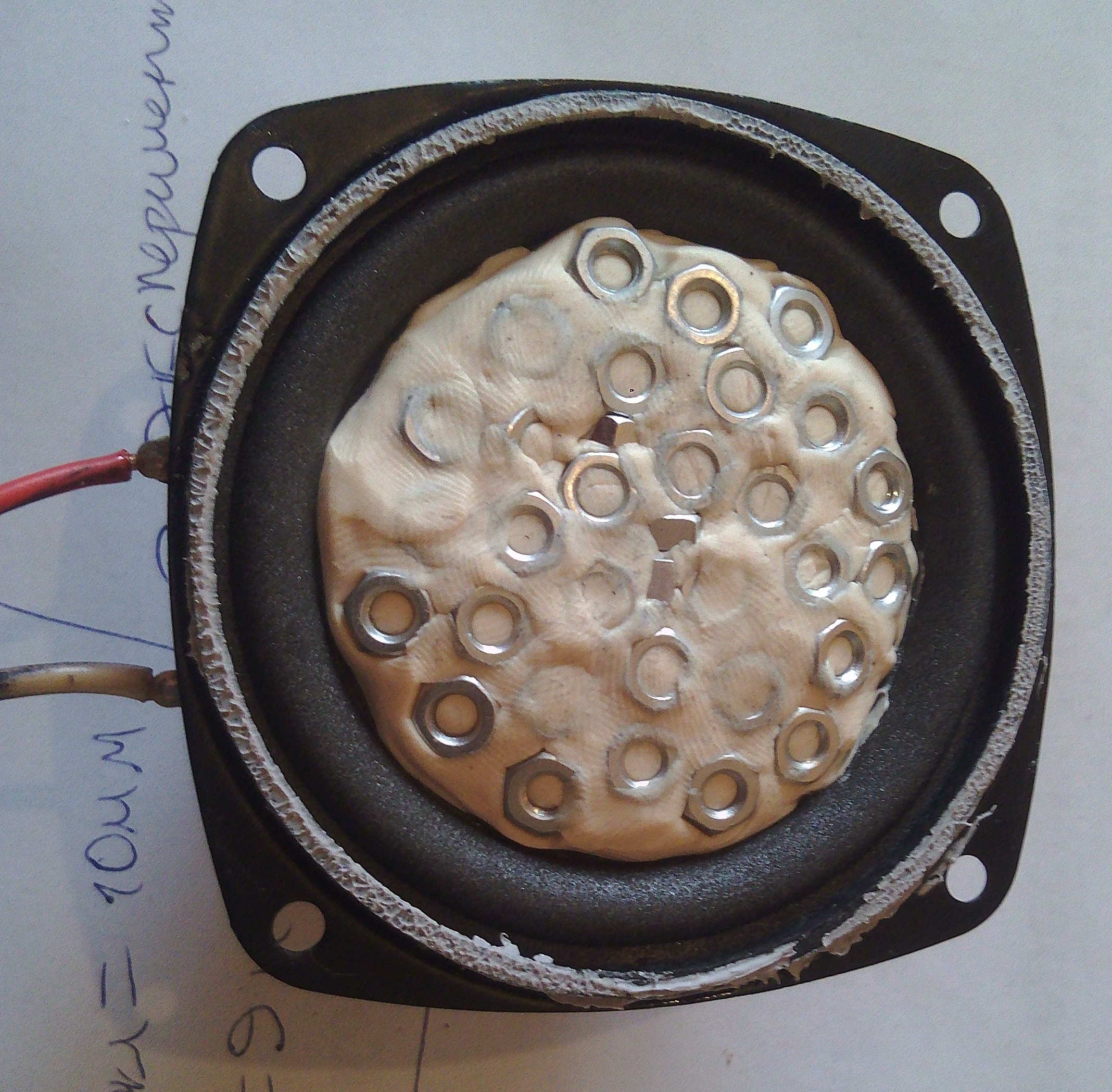
Fig. 16. - A speaker encrusted with nuts on the diaphragm. (object of modern art)
And really it worked, as expected. It was possible to change the engine operating mode to work with the main frequency. There were even very interesting transients, when with a certain mass stuck on the diaphragm, the engine either ran at the main frequency, then later, as the hot heat exchangers cooled down, it started to run at the tripled frequency. Interestingly, the engine cannot work at doubled frequency. Either on the main, or on the triple. Apparently the wave parameters at a double frequency are not suitable for maintaining the operation of this device.
When using a speaker and an engine with air under atmospheric pressure as a working fluid, the energy conversion efficiency turned out to be negligible.
In order to achieve efficiency levels of 20 - 40% of the Carnot cycle, it is necessary to increase the pressure in the engine, replace the working gas with helium or argon and use other methods of generating electricity than a conventional speaker.
