Cable TV networks for the smallest. Part 5: Coaxial Distribution Network

After going through the theoretical foundations, we turn to the description of the hardware of cable television networks. I will start the story from the subscriber’s television and, in more detail, than in the first part I ’ll talk about all the components of the network.
Content Series
Cables
The TV jack is connected to a divider inside the apartment, or (if there is only one TV) with a riser in the flap on the stairs. As you know, every extra connection is a potential malfunction, so when looking for problems, you should pay close attention to each joint.
Inside the apartment and to the panel, as a rule, a well-known coaxial cable of the RG- 6 type is laid, which terminates in simple connectors, which usually have contact only with the braid, and the central core enters the connector of the device or adapter “as is”.


For the laying of highways, an RG-11 cable is used, which has less attenuation by length and greater strength. There is also a self-supporting version of such a cable with a steel cable in a braid for laying “air”.
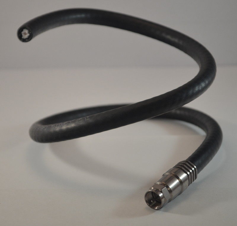
This cable is thicker and stiffer, therefore, more complex connectors are already used for termination: these are either crimp connectors similar to smaller brothers, or composite threaded structures inherent in industrial-grade equipment.
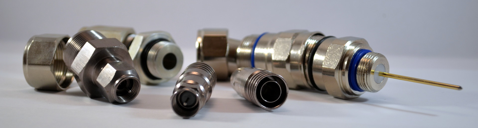
Crimping the connector on such a cable can be difficult and often problems arise immediately after installation due to non-compliance with the standard for stripping length (6.3 mm central core + 6.3 mm braid), or then, due to poor contact during crimping without a special tool.
Taps and splitters
When building a riser, splitters and taps are used.
Inside, they are an isolation of LC circuits for matching the impedance of the terminals. If you separate the coaxial cable without such a device, but simply with twists, then the resistance of each of the taps, which decreases when parallel connected, will not allow the signal to completely pass through and part of it will be reflected back to the trunk, which will lead to noise and noise in the signal.
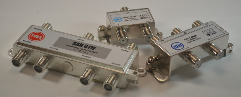
The fundamental difference between taps and splitters is the presence or absence of a linear output (OUT). Losses at this output are minimal and amount to about 1-5 dB, depending on the nominal value. At the subscriber tap (TAP) attenuation from 8 to 30 or more dB. This is necessary to ensure the same signal level at subscriber taps at different levels in the trunk.
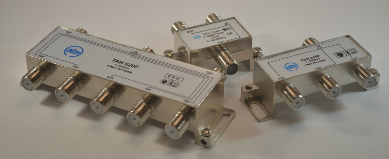
If at the beginning of the riser we have a signal with a level of 105dBμV, then in order to give the subscriber from the tap the set 75dBμV, it is necessary to install a splitter that dampens 30dB. And to the far end on the highway can reach less than 85dB, in which case it is necessary to install a splitter, the losses at the taps of which are minimal and for 4-pin are 8dB. The attenuation rating and the number of conclusions for almost all manufacturers are encoded in the device marking: in the picture above, for example, we see 620 - 6 subscriber taps, which are extinguished by 20dB each and one trunk. The designation of TAH and SAH is not generally accepted, but it is very common and, accordingly, means tap or splitters.
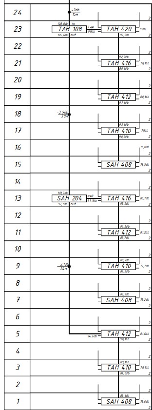
To reduce the difference in signal level between sections of the riser, in high-rise buildings, it is necessary to break it into several parts using trunk couplers. This allows you to reduce the range of subscriber taps and provide the level as close to the desired level on the subscriber tap.
In the diagram on the left, I showed an example of a riser built from top to bottom and divided into three parts (“pilasters”). Only 5 types of subscriber couplers are used on 12 floor flaps. If there were no separation, then 12 species would have to be used in increments of 2-3 dB. And for the far end, we most likely would not have been able to pick up a splitter, since even having only two pins “doubles” it attenuates 4 dB, and with more pins we can no longer fit into the budget for attenuation.
If the system uses a remote power supply of the equipment (I will tell you about it in the following parts), the trunk couplers look a little different:
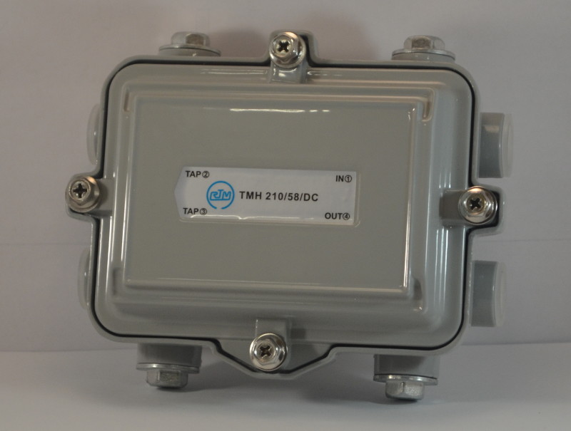
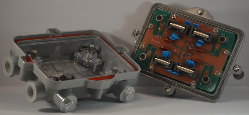
Due to the massive case and thoughtful design, better isolation of live parts from external influences and the external environment from considerable current is provided that can walk on cable.
Security elements
To protect the equipment from possible incidents on the cable, as well as subscribers from malfunctions of the active equipment, insulators are installed at the beginning of the risers, which provide galvanic isolation between the main part and the distribution part.

To exclude signal reflection from inconsistent outputs (structurally, these are only through-out bends, but it is possible that with poor-quality assembly or a defect in the coupler, the subscriber will also have wave impedance different from the required one) they should be blocked by matched absorbing plugs, which often carry the same function "Secrets" in the case when tenants conclude individual contracts for the provision of services.