Homemade Qi standard receiver
- Transfer
- Tutorial
A wireless charging system could be made "stupid", but then it would not distinguish the receiving part from metal objects and would heat them with eddy currents. Therefore, when there is no receiving part, the transmitter periodically sends short pulses. When they bring the receiving part, it begins to send packets telling the transmitting part what power is required from it.
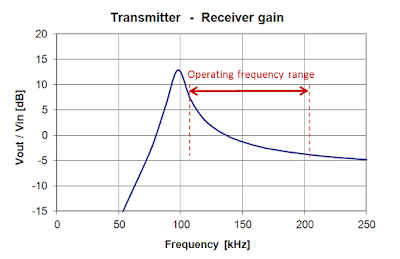
The transmitting part begins to generate oscillations continuously, while it regulates the power, changing the frequency relative to the resonance, as shown in the graph. The farther the frequency from the resonant, the lower the transmitted power.
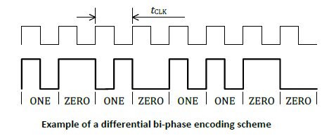
To transmit bits from the receiving part to the transmitting one, two transistors connect capacitors of small capacity to the receiving circuit. The way to encode zeros and ones is here:
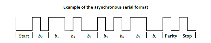
In this case, errors are possible, their correction is necessary. Each byte is transmitted in eleven bits, the first of which is the start bit, always equal to zero, then eight bits of the byte itself follow, then the parity bit (set to one if the byte contains an even number of units), then the stop bit, always equal to one . If the parity bit does not match, the byte is considered received incorrectly.
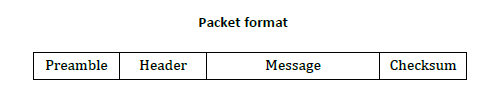
A package consists of an introduction, a header, a message, and a checksum. The entry contains from 11 to 25 units. If the checksum does not match, the entire packet is considered incorrectly accepted.
A more detailed specification of the standard is here .
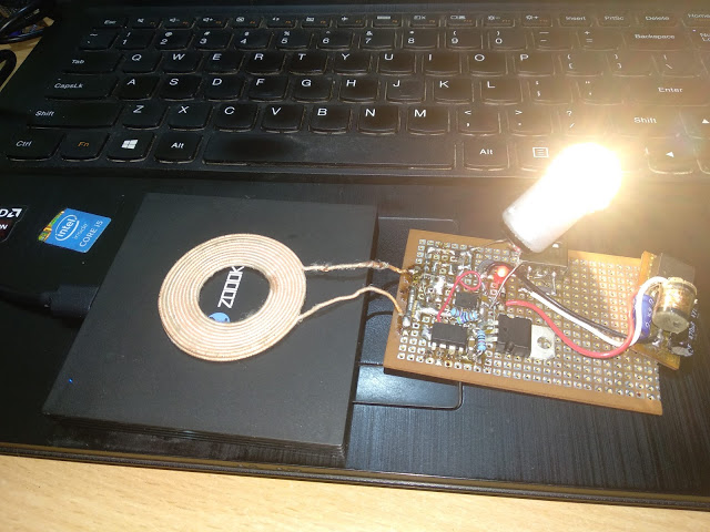
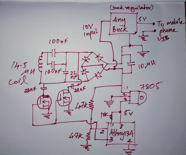
A home-made receiving part consists of a circuit (a winding of 10 turns with an inductance of 14.5 μG, two capacitors of 100 nF and one of 22 nF), a rectifier, a filter (10 μF capacitor), two transistors connecting 22 nF capacitors to the circuit , two stabilizers - pulse for the load (ready-made charging in the cigarette lighter on the MC34063 is also suitable) and linear for the microcontroller, a resistor divider for supplying voltage removed from the rectifier to the analog input of the microcontroller, as well as the microcontroller itself. The task of the program is to control transistors and send commands to the transmitting part, which, in spite of load changes, must maintain such transmitted power so that the voltage at the rectifier output is 10 V.
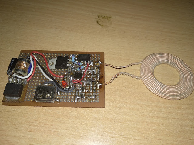
Appearance of the entire device and the board separately:

Firmware -here .
Video: