Cable TV networks for the smallest. Part 2: Composition and waveform

A signal transmitted over a cable television network is a broadband, frequency-divided spectrum. Signal parameters, including frequency and channel numbers in Russia are regulated by GOST 7845-92 and GOST R 52023-2003, but the operator is free to choose the content of each channel at his discretion.
Content of a series of articles
Let me remind you that I am not writing a textbook, but an educational program for expanding my horizons and entering the world of cable TV. Therefore, I try to write in simple language, leaving keywords for those who are interested and not go deep into the description of technologies that without me have been perfectly described hundreds of times.
Than we measure
To obtain information about the signal in the coaxial cable, our technical staff mainly uses the Deviser DS2400T.

In fact, it is a television receiver, but instead of image and sound, we see quantitative and qualitative characteristics of both the entire spectrum and individual channels. The illustrations below are screenshots from this device.
Such a Deviser even has a somewhat redundant functionality, but there are also abrupt devices: with a screen showing the TV image directly, receiving an optical signal and, what Deviser lacks, receiving a DVB-S satellite signal (but this is a completely different story).
Signal spectrum
The spectrum display mode allows you to quickly assess the state of the signal “by eye”.

In this mode, the device scans the channels in accordance with the specified frequency plan. For convenience, frequencies not used in our network have been removed from the full spectrum, so the resulting image is a channel picket.
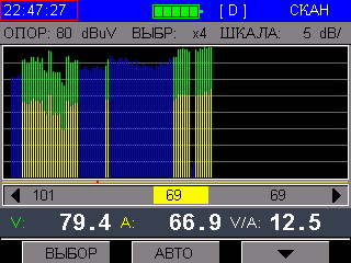
Blue channels indicate digital channels, yellow - analogue channels. The green part of the analog channel is the difference between the audio and video components of the signal (according to GOST it should be from 10 to 20 dB).
The difference in the levels of different channels is clearly noticeable: a separate unevenness depends on the settings of the transponders at the headend, and the general difference between the upper and lower frequencies has a certain meaning, which I will discuss below.
In this mode, strong deviations from the norm will be clearly visible and if there are serious problems in the network, then this will immediately become visible. For example, in the above image you can see the omission of two digital channels in the high-frequency zone: they are present only in the form of short strips that barely reach the level of 10 dBmV (the reference level of 80 dBmV is indicated at the top - this is the upper boundary of the graph), which is actually the noise that the cable receives on yourself as an antenna or introduced by active equipment. These two channels are test ones and were off at the time of writing.
Perplexity can cause uneven arrangement of digital and analog channels. This, of course, is not correct and was due to the evolutionary development of the network: additional channels were simply added to the frequency plan in the free part of the spectrum. When creating a frequency plan from scratch, it would be correct to place the entire analog in the lower part of the spectrum. In addition, the station equipment designed for signal generation for European countries has restrictions on the use of frequencies for broadcasting a digital signal, and although in our country there are no such restrictions, using such equipment it is necessary to place digital channels in the spectrum contrary to logic.
Waveform
As is known from fundamental physics, the higher the wave frequency, the stronger its attenuation as it propagates. When transmitting such a broadband signal as the attenuation in the KTV network, the attenuation in the distribution network can reach tens of decibels per shoulder, and in the lower part of the spectrum it will be several times smaller. Therefore, sending an even signal to the riser from the basement, on the 25th floor we will see something like the following:
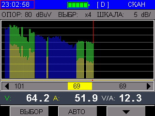
The level of high frequencies is noticeably lower than the lower ones. In a real situation, the TV, without understanding, can consider the weaker channels just noise and filter them out. And if an amplifier is installed in the apartment, then when you try to configure it for high-quality reception of channels from the upper part of the range, an over-amplification will occur in the lower one. Standards regulate the difference of not more than 15 dBμV for the entire range.
To avoid this, when setting up active equipment, a higher level in the high-frequency zone is initially laid. This is called a “straight slope”, or simply “slope”. And what is shown in the image is a “reverse tilt”, and such a picture is already an accident. Or, at least, an indication that with a cable to the measuring point is a disaster.
There is the opposite situation, when low frequencies are practically absent, and the upper ones barely break through above the noise level:
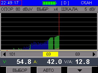
This also tells us about damage to the cable, namely its central core: the higher the frequency, the closer to the edge of the waveguide it spreads (skin effect in UPD coaxial cable : with regards to the physical basis of this phenomenon, there are disagreements, more in the comments) Therefore, we see only those channels that are distributed at higher frequencies, but, as a rule, the TV will not be able to receive them at this level.