We control the generator or the fight against the ADC in the STM32F030
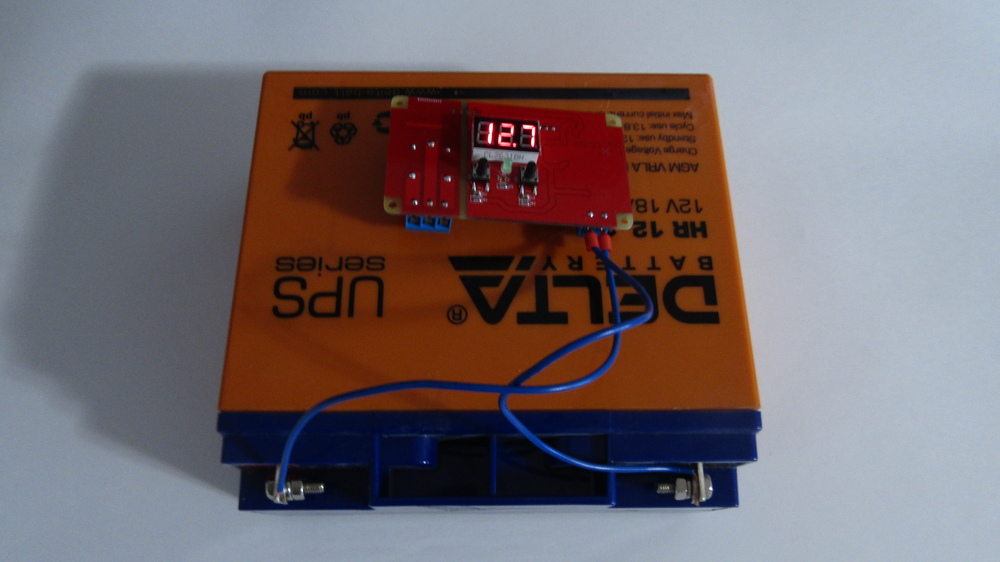
It somehow historically did not work out for me with the STM32F030 family, about 5 years ago I tried to work with them and for a long time was surprised at the clumsy work of most of the peripherals, and then scored on them. And the other day I still had to return to this series, it was necessary to measure for minimal money the constant voltage on a lead battery (or assembly of up to 4 pieces in series) from 8 to 60V with an accuracy of no worse than ± 0.1V with a low polling frequency.
The solution of the “head-on” problem made it possible to accurately measure the voltage only when the value of the ADC input is more than 1.5 ... 1.6V, that is, only in the second half of the range, which meant 30 ... 60V for me instead of the required 8 .. .60V. The main problem was in the interval 0 ... 1.6V, it all looked as if my voltage divider “floated” or the reference voltage for the ADC (V ref) was extremely unstable.
It was necessary to quickly solve the problem, albeit not in the most elegant way, but at least without obvious crutches. To do this, it was first necessary to study the problem and understand where the “legs grow” from, and then eliminate this problem. If it doesn’t work out, then at least get around it in order to eventually get a working device and send it to the customer.
In general, I’ve been trying not to tackle such a trifle for a long time, but then a relative approached me, and part-time a good person who also works on topics that are close to me — he collects small SES somewhere in the Moscow Region. I did not want to refuse, and even at that moment this task seemed to me “a couple of hours of iron + a couple of hours of code”. The project in Altium Designer really took me a couple of hours, but the fight against the ADC was eaten all evening, so I decided to share information so that others would not waste time.
The device itself is extremely simple, the algorithm is as follows:
All! Example: there is one 12V battery and the inverter is powered from it. If the voltage drops below the "lower threshold", the default is 10.2V, then turn on the generator. If the voltage on the battery has increased to "lower threshold + hysteresis", then turn it off. By default, the hysteresis is set to 2V and is needed so that the gasoline generator does not cut down as soon as it slightly charges the battery to 10.3V. From constant on / off, the generator will simply die. Well, just in case, protection: if the voltage on the battery is above 14.4V, then do not turn on the generator exactly.
The algorithm is simple and clear, in addition, it was necessary to make a small menu so that three variables could be changed: “lower threshold”, “hysteresis”, “upper threshold”. Nothing complicated, but the devil is in the details.
Initially, the company where the relative works used a Chinese device with similar functionality. Of the minor drawbacks - it was impossible to change the hysteresis, for the power needed an additional source of 5V and a measurement of only 30V, that is, for 1 or 2 batteries. Of the big minuses - the Chinese device sometimes freezes and reboots at the time of the start of the gasoline generator that it controlled. The last "feature" just became the reason for the attempt to abandon the Chinese decision.
They wanted to eliminate all these disadvantages from me and that the price of the device was like that of the Chinese, that is, $ 10. The “devilish trifle” in this case was that they wanted to buy a finished device from me for $ 10 in batches of only 20-30 pieces, though it was stable and often enough. That is, I had to make the device much better and very much cheaper than the Chinese in a small series, I also need to earn money in the future. Yeah, I was also funny in the first 10 minutes, but by the time I realized this situation, I already said “YES”, that is, there was no land beyond the Volga for me ...
As I wrote above, the main problem is the unstable operation of the device during the start of the generator. As a result, a Chinese device with aliexpress was purchased for testing and research. The main reason for the “demolition of the head” was not in the generator, but in the relay :)) At the time of switching over the power supply, a pulse with an amplitude of about 25V passed through the 3.3V bus, which kind of hinted ... The interference also went to the signal circuits. In the Chinese circuit, to combat such a problem, LL4148 diodes stood, which type blocked the path of interference. This turned out to be enough for the device to work normally on the table, but not in a heap of external additional interference such as a generator and other equipment. To permanently get rid of the above, I decided to use galvanic isolationthrough a bunch of “optron + dc / dc”, which completely eliminated the electrical contact and the path of interference between the control relay coil and the rest of the circuit.
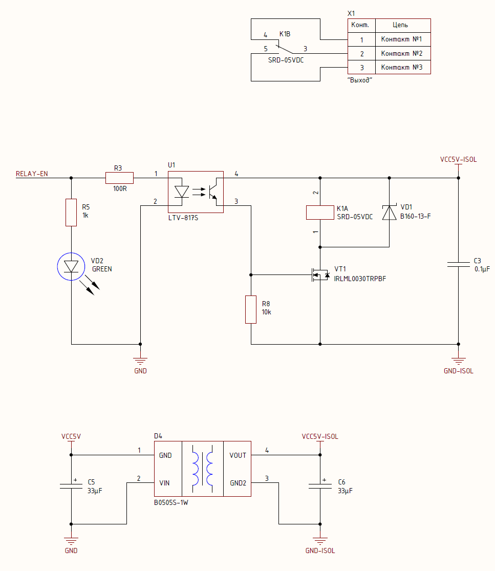
An alternative to this solution was the use of protective TVS diodes together with a common-mode choke, as well as the complication of the power supply filter. But why such a collective farm? Putting dc / dc is easier, but in practice it turned out even cheaper - the Chinese module Mornsun B0505S-1WR2 cost me $ 0.4 with the cost of a common-mode choke per small batch of about $ 0.32.
As a result, after such a decision and prototype testing, the device began to work as a Kalashnikov assault rifle and the problems with rebooting were gone. In general, I’m a little surprised that the relay + a bit the generator still forced to reboot the stm-ku, the Chinese developers, in principle, did everything well: 10 kOhm + 0.1 uF to reset, blocking capacitors for power, ferrite beads, everything was, but it turned out to be the same anyway few.
The second minus of the "Chinese" was the need for additional power, apparently saved on dc / dc. I solved the problem in the forehead - I took power from the input signal, directly from one connector. To do this, you just had to put dc / dc, which will digest at least 4 * 14.4V, i.e. 57.6V. My choice fell on the LMR16010PDDAR. Firstly, this is Texas and that’s it. Secondly, the Asian comrades suggested that I carry this chip very cheaply.
The previous paragraph comprehensively decided the third minus - the ability to connect up to 4 batteries in series. DC / DC easily digests 60V, starts trying to burn out only at 72 ... 73V, so the maximum 57.6V is definitely not scary for him. The voltage divider in general does not care how much is at the input, so everything was decided with minimal effort.
You can see how all this is implemented in the diagram here - PDF . The scheme is large enough, so I did not fill it with a picture. By the way, in pdf you can also see dimensions with a printed circuit board, but there is nothing supernatural.
As a result, components for 10 devices were ordered for the first test and test batch, and after assembly it turned out like this: There were
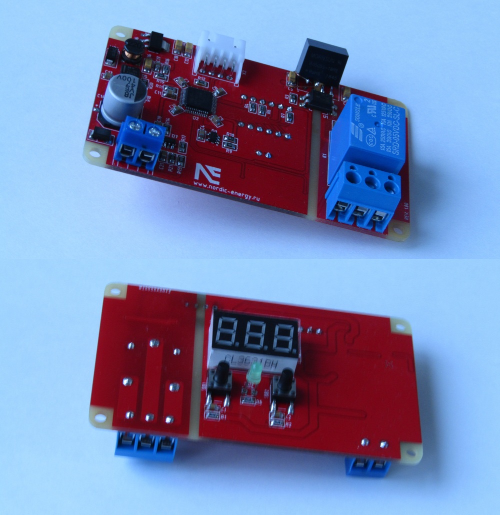
no incidents - when I created the component for the dc / dc module I mixed the legs 1 and 2 in places, I had to take a little farm. Although I did it more carefully on subsequent boards so that no one noticed, the board in the photo remained with me as a debugging tool just in case or for software improvements if the customer came up with something during testing.
Now let's move on to the main part of the article. As I wrote at the beginning of the article, the F030 ADC turned out to be inaccurate, that is, up to a voltage of 30 ... 32V at the input of the device, the readings floated with a deviation of up to 15 ... 20%, and then the error gradually disappeared. One thing pleased me - at first glance, the deviations had some regularity, which means that this is not a random error and you can track it and try to correct it.
Let's take a little more details about the error ... After the conversion, the ADC sends the raw data to the DR register , which contains a value from 0 to 4095 (2 12) To convert this value to voltage, you need to multiply it by the quantization step. In my case, the voltage at the VDDA pin, from which the ADC takes the support, was 3.3072V and, accordingly, the step is 3.3072V / 4096 = 0.000807V, I rounded it to 0.0008. To get the voltage at the input of the device, the obtained voltage needs to be multiplied by the coefficient of the voltage divider, in my case the resistor in the upper arm is 100 kOhm, and in the lower arm 4.7 kOhm, which gives the divider 22.2765. Based on this, the voltage at the input of the device, that is, the battery voltage, is found using the formula:
It turns out that after reading the data ADC1-> DR , they are converted to the type float and simply multiplied by the coefficients, which are constants, and we get the result in the usual volts. In practice, it turned out that everything is very bad with accuracy.
Remembering Hanlon's razor, I began to look for the place where I had made a mistake. First I checked the voltage on the leg of the VDDA, I thought that it somehow floats and depends on the input voltage, for example, the LDO is faulty. Armed with a desktop multimeter, he monitored the voltage on the VDDA and changed the input voltage from 8 to 60V, while the voltage on the leg of the VDDA stayed dead at 3.3072V, only the following 2 signs floated, which is very good for a 10-cent linear gauge.
The next place for potential error was the voltage divider. Although it seemed strange to me that the resistors from Bourns are ± 0.1% floating so that the data has an error of up to 20% and this error is non-linear. I conducted the same experiment: I measured the voltage after the divider with a multimeter, and changed the input voltage in 0.5V steps, and as a result, the divider coefficient was also tightly fixed at 22.2768.
At that moment, it began to become interesting. There was only one component that I could doubt - the LMV611MFX operational amplifier. This op amp is included as a voltage follower. The voltage BEFORE and AFTER it was the same up to 4 decimal places. Strange ... By the datasheet it’s not bad and it’s the same TI, I doubted it, but decided to check it, because it is this opamp never used. Just in case, my favorite and tested in a heap of OPA320 projects, which I have in the coils, soldered in his place and he showed the same result.
The last component remained - MK, namely its ADC. Over the years of using STM, I’m used to trusting their products, especially since I only take the originals, so I thought at MK last. The first thing I thought was that I forgot to calibrate or did it wrong. Useful in the reference manual, they demanded not only to cut down the ADC by writing zero to the ADEN bit , but also set 1 to ADDIS and 0 to DMAEN . The last 2 steps have not been taken, usually I cut down the ADC and everything works well, as a result, I corrected a piece of code with calibration:
Unfortunately, it didn’t help and decided to conduct the following experiment ... I already checked the coefficients and they are 100% correct, so I will apply voltage from the laboratory power supply to the input, change it and display the raw results of the ADC measurement on a seven-segment indicator, and then compare it with what should to be there with what you really measured. As a result, I got the following results:
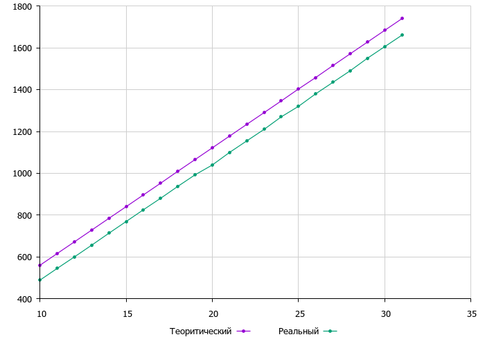
As you can see, the theoretical graph has excellent linearity, because not attached to iron. The graph based on real data is also almost linear with minimal deviations. In fact, the graph with real data can be combined with the theoretical graph by parallel transfer to a certain constant. Speaking in the language of electronics, the ADC has an offset!
According to the data on which the graphs were built, I found out that the ADC has an offset at different points of 71 ... 73 steps. That was the problem, and I thought “non-linearity” because the shift of 71 steps at 10V is about 14%, and at 30V it is already 4%. That is, if you construct a graph of deviations in%, then the dependence will have an exponential form, but such a graph is not interesting.
It was decided that to clarify the results, try to introduce another variable into the formula, which will shift my values up and have the following form:
After these simple manipulations, my device began to accurately measure the voltage and the data stopped floating. Until that moment, it lied at 72 * 0.0008V * 22.2768 = 1.28V , which is very critical in the case of control of one battery. The lead battery certainly does not explode like Li-ion, but it still crashes quickly, especially if it is discharged constantly not to 10.2V, but to 8.92V.
Here is such a small story about a small piece of iron. I hope someone will find this material useful or at least just interesting to read. Be careful with all these ADCs and other nasty things :))
UPD. olartamonovvery diligently asks not to fool people and use the calibration code from the reference manual - made the change with pleasure. Unfortunately, in my case, this did not change the situation and the shift did not go anywhere. Probably the problem is in the chip itself.as directed from the State Department threw counterfeit products
A competition among technical projects is taking place among PCBway comrades , anyone can participate. The rules are simple. Printed circuit boards for your project will do for free. And most importantly prizes! These are some green papers with American gentlemen on your paypal + virtual currency for which you can order printed circuit boards + honor and respect + the opportunity to get a job offer somewhere outside the CIS :)) I especially recommend students to participate, the technical level is not too high there , although from the experience of past contests there are very strong projects, so a “strong” DIY box can easily get into the winners!

The solution of the “head-on” problem made it possible to accurately measure the voltage only when the value of the ADC input is more than 1.5 ... 1.6V, that is, only in the second half of the range, which meant 30 ... 60V for me instead of the required 8 .. .60V. The main problem was in the interval 0 ... 1.6V, it all looked as if my voltage divider “floated” or the reference voltage for the ADC (V ref) was extremely unstable.
It was necessary to quickly solve the problem, albeit not in the most elegant way, but at least without obvious crutches. To do this, it was first necessary to study the problem and understand where the “legs grow” from, and then eliminate this problem. If it doesn’t work out, then at least get around it in order to eventually get a working device and send it to the customer.
Essence of the task
In general, I’ve been trying not to tackle such a trifle for a long time, but then a relative approached me, and part-time a good person who also works on topics that are close to me — he collects small SES somewhere in the Moscow Region. I did not want to refuse, and even at that moment this task seemed to me “a couple of hours of iron + a couple of hours of code”. The project in Altium Designer really took me a couple of hours, but the fight against the ADC was eaten all evening, so I decided to share information so that others would not waste time.
The device itself is extremely simple, the algorithm is as follows:
- measure the voltage on the assembly of 1 ... 4 series-connected lead batteries;
- if the voltage is less than the "lower threshold", then close the relay and it turns on the generator, which charges our batteries;
- if the voltage rises above the "lower threshold + hysteresis", that is, the batteries are charged to the set threshold, then turn off the generator;
- if the voltage is above the "upper threshold", then we prohibit turning on the generator just in case.
All! Example: there is one 12V battery and the inverter is powered from it. If the voltage drops below the "lower threshold", the default is 10.2V, then turn on the generator. If the voltage on the battery has increased to "lower threshold + hysteresis", then turn it off. By default, the hysteresis is set to 2V and is needed so that the gasoline generator does not cut down as soon as it slightly charges the battery to 10.3V. From constant on / off, the generator will simply die. Well, just in case, protection: if the voltage on the battery is above 14.4V, then do not turn on the generator exactly.
The algorithm is simple and clear, in addition, it was necessary to make a small menu so that three variables could be changed: “lower threshold”, “hysteresis”, “upper threshold”. Nothing complicated, but the devil is in the details.
Initially, the company where the relative works used a Chinese device with similar functionality. Of the minor drawbacks - it was impossible to change the hysteresis, for the power needed an additional source of 5V and a measurement of only 30V, that is, for 1 or 2 batteries. Of the big minuses - the Chinese device sometimes freezes and reboots at the time of the start of the gasoline generator that it controlled. The last "feature" just became the reason for the attempt to abandon the Chinese decision.
They wanted to eliminate all these disadvantages from me and that the price of the device was like that of the Chinese, that is, $ 10. The “devilish trifle” in this case was that they wanted to buy a finished device from me for $ 10 in batches of only 20-30 pieces, though it was stable and often enough. That is, I had to make the device much better and very much cheaper than the Chinese in a small series, I also need to earn money in the future. Yeah, I was also funny in the first 10 minutes, but by the time I realized this situation, I already said “YES”, that is, there was no land beyond the Volga for me ...
Solving Iron Problems
As I wrote above, the main problem is the unstable operation of the device during the start of the generator. As a result, a Chinese device with aliexpress was purchased for testing and research. The main reason for the “demolition of the head” was not in the generator, but in the relay :)) At the time of switching over the power supply, a pulse with an amplitude of about 25V passed through the 3.3V bus, which kind of hinted ... The interference also went to the signal circuits. In the Chinese circuit, to combat such a problem, LL4148 diodes stood, which type blocked the path of interference. This turned out to be enough for the device to work normally on the table, but not in a heap of external additional interference such as a generator and other equipment. To permanently get rid of the above, I decided to use galvanic isolationthrough a bunch of “optron + dc / dc”, which completely eliminated the electrical contact and the path of interference between the control relay coil and the rest of the circuit.
An alternative to this solution was the use of protective TVS diodes together with a common-mode choke, as well as the complication of the power supply filter. But why such a collective farm? Putting dc / dc is easier, but in practice it turned out even cheaper - the Chinese module Mornsun B0505S-1WR2 cost me $ 0.4 with the cost of a common-mode choke per small batch of about $ 0.32.
As a result, after such a decision and prototype testing, the device began to work as a Kalashnikov assault rifle and the problems with rebooting were gone. In general, I’m a little surprised that the relay + a bit the generator still forced to reboot the stm-ku, the Chinese developers, in principle, did everything well: 10 kOhm + 0.1 uF to reset, blocking capacitors for power, ferrite beads, everything was, but it turned out to be the same anyway few.
The second minus of the "Chinese" was the need for additional power, apparently saved on dc / dc. I solved the problem in the forehead - I took power from the input signal, directly from one connector. To do this, you just had to put dc / dc, which will digest at least 4 * 14.4V, i.e. 57.6V. My choice fell on the LMR16010PDDAR. Firstly, this is Texas and that’s it. Secondly, the Asian comrades suggested that I carry this chip very cheaply.
The previous paragraph comprehensively decided the third minus - the ability to connect up to 4 batteries in series. DC / DC easily digests 60V, starts trying to burn out only at 72 ... 73V, so the maximum 57.6V is definitely not scary for him. The voltage divider in general does not care how much is at the input, so everything was decided with minimal effort.
You can see how all this is implemented in the diagram here - PDF . The scheme is large enough, so I did not fill it with a picture. By the way, in pdf you can also see dimensions with a printed circuit board, but there is nothing supernatural.
As a result, components for 10 devices were ordered for the first test and test batch, and after assembly it turned out like this: There were
no incidents - when I created the component for the dc / dc module I mixed the legs 1 and 2 in places, I had to take a little farm. Although I did it more carefully on subsequent boards so that no one noticed, the board in the photo remained with me as a debugging tool just in case or for software improvements if the customer came up with something during testing.
Fighting ADC accuracy
Now let's move on to the main part of the article. As I wrote at the beginning of the article, the F030 ADC turned out to be inaccurate, that is, up to a voltage of 30 ... 32V at the input of the device, the readings floated with a deviation of up to 15 ... 20%, and then the error gradually disappeared. One thing pleased me - at first glance, the deviations had some regularity, which means that this is not a random error and you can track it and try to correct it.
Let's take a little more details about the error ... After the conversion, the ADC sends the raw data to the DR register , which contains a value from 0 to 4095 (2 12) To convert this value to voltage, you need to multiply it by the quantization step. In my case, the voltage at the VDDA pin, from which the ADC takes the support, was 3.3072V and, accordingly, the step is 3.3072V / 4096 = 0.000807V, I rounded it to 0.0008. To get the voltage at the input of the device, the obtained voltage needs to be multiplied by the coefficient of the voltage divider, in my case the resistor in the upper arm is 100 kOhm, and in the lower arm 4.7 kOhm, which gives the divider 22.2765. Based on this, the voltage at the input of the device, that is, the battery voltage, is found using the formula:
float voltageReference = 0.0008;
float voltageDivider = 22.2765;
adcVoltageResult = (float)adcData * voltageReference * voltageDivider;
It turns out that after reading the data ADC1-> DR , they are converted to the type float and simply multiplied by the coefficients, which are constants, and we get the result in the usual volts. In practice, it turned out that everything is very bad with accuracy.
Remembering Hanlon's razor, I began to look for the place where I had made a mistake. First I checked the voltage on the leg of the VDDA, I thought that it somehow floats and depends on the input voltage, for example, the LDO is faulty. Armed with a desktop multimeter, he monitored the voltage on the VDDA and changed the input voltage from 8 to 60V, while the voltage on the leg of the VDDA stayed dead at 3.3072V, only the following 2 signs floated, which is very good for a 10-cent linear gauge.
The next place for potential error was the voltage divider. Although it seemed strange to me that the resistors from Bourns are ± 0.1% floating so that the data has an error of up to 20% and this error is non-linear. I conducted the same experiment: I measured the voltage after the divider with a multimeter, and changed the input voltage in 0.5V steps, and as a result, the divider coefficient was also tightly fixed at 22.2768.
At that moment, it began to become interesting. There was only one component that I could doubt - the LMV611MFX operational amplifier. This op amp is included as a voltage follower. The voltage BEFORE and AFTER it was the same up to 4 decimal places. Strange ... By the datasheet it’s not bad and it’s the same TI, I doubted it, but decided to check it, because it is this opamp never used. Just in case, my favorite and tested in a heap of OPA320 projects, which I have in the coils, soldered in his place and he showed the same result.
The last component remained - MK, namely its ADC. Over the years of using STM, I’m used to trusting their products, especially since I only take the originals, so I thought at MK last. The first thing I thought was that I forgot to calibrate or did it wrong. Useful in the reference manual, they demanded not only to cut down the ADC by writing zero to the ADEN bit , but also set 1 to ADDIS and 0 to DMAEN . The last 2 steps have not been taken, usually I cut down the ADC and everything works well, as a result, I corrected a piece of code with calibration:
    /* disable ADC */
    if (ADC1->CR & ADC_CR_ADEN) {
        ADC1->CR |= ADC_CR_ADDIS;
        while (ADC1->CR & ADC_CR_ADEN) {}
    }
    /* calibrate ADC */
    ADC1->CR |= ADC_CR_ADCAL;
    while(ADC1->CR & ADC_CR_ADCAL) {}
    /* reset configuration */
    ADC1->CFGR2 = 0;
    /* enable device */
    ADC1->CR = ADC_CR_ADEN;
    while(!(ADC1->ISR & ADC_ISR_ADRDY));
Unfortunately, it didn’t help and decided to conduct the following experiment ... I already checked the coefficients and they are 100% correct, so I will apply voltage from the laboratory power supply to the input, change it and display the raw results of the ADC measurement on a seven-segment indicator, and then compare it with what should to be there with what you really measured. As a result, I got the following results:
As you can see, the theoretical graph has excellent linearity, because not attached to iron. The graph based on real data is also almost linear with minimal deviations. In fact, the graph with real data can be combined with the theoretical graph by parallel transfer to a certain constant. Speaking in the language of electronics, the ADC has an offset!
According to the data on which the graphs were built, I found out that the ADC has an offset at different points of 71 ... 73 steps. That was the problem, and I thought “non-linearity” because the shift of 71 steps at 10V is about 14%, and at 30V it is already 4%. That is, if you construct a graph of deviations in%, then the dependence will have an exponential form, but such a graph is not interesting.
It was decided that to clarify the results, try to introduce another variable into the formula, which will shift my values up and have the following form:
uint16_t offsetVoltage = 72;
float voltageReference = 0.0008;
float voltageDivider = 22.2765;
adcVoltageResult = ((float)(adcData+offsetVoltage))*voltageReference*voltageDivider;
After these simple manipulations, my device began to accurately measure the voltage and the data stopped floating. Until that moment, it lied at 72 * 0.0008V * 22.2768 = 1.28V , which is very critical in the case of control of one battery. The lead battery certainly does not explode like Li-ion, but it still crashes quickly, especially if it is discharged constantly not to 10.2V, but to 8.92V.
Here is such a small story about a small piece of iron. I hope someone will find this material useful or at least just interesting to read. Be careful with all these ADCs and other nasty things :))
UPD. olartamonovvery diligently asks not to fool people and use the calibration code from the reference manual - made the change with pleasure. Unfortunately, in my case, this did not change the situation and the shift did not go anywhere. Probably the problem is in the chip itself.
Competition
A competition among technical projects is taking place among PCBway comrades , anyone can participate. The rules are simple. Printed circuit boards for your project will do for free. And most importantly prizes! These are some green papers with American gentlemen on your paypal + virtual currency for which you can order printed circuit boards + honor and respect + the opportunity to get a job offer somewhere outside the CIS :)) I especially recommend students to participate, the technical level is not too high there , although from the experience of past contests there are very strong projects, so a “strong” DIY box can easily get into the winners!