Energy, heat and water
Foreword
2019 year. In almost any electronics store, you can buy one of hundreds of possible sets of smart homes. Take and configure in “2 clicks”, connect to the clouds, receive push events in the application / SMS, and in general receive all the necessary information anywhere in the world.
Ideal, but in my case it didn’t work. A few decisions that fell into my hands turned out to be a limited set of certain functions, covering only part of my queries, and besides, imposing almost insurmountable restrictions. And, as it usually happens, the less restrictions, the more you need to dive into the subject area, independently think through solutions, architectures. Therefore - the collective farm ourselves :)
Tasks
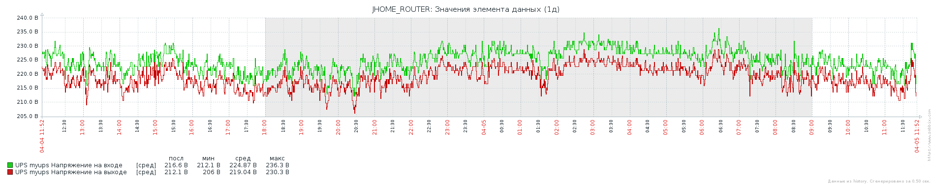
1. receive information about the quality of the power network (power surges, complete shutdown, etc.).
2. Have full UPS monitoring. But in fact, to have this same UPS based on the consequences of p2.
3. Receive temperature information:
- outside
- at home
- in the attic (when the trash and tomatoes thrown in there freezes)
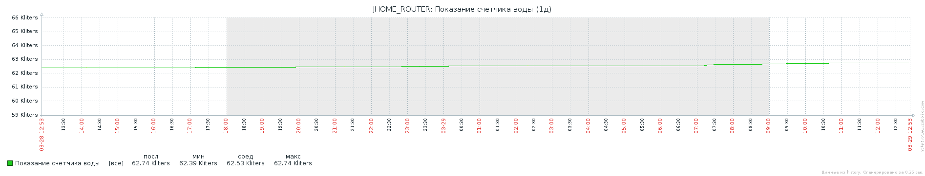
4. Monitor the state of water consumption, alert if consumption has increased (suddenly a leak, you can’t weigh everything with moisture sensors).
5. Understand when someone is at home to automate the shutoff / opening of water.
6. Reading the gas meter and alert when the paid reserve runs out.
+ other all kinds of sensors (humidity, opening, water pressure, pressure in the heating circuit, etc.).
The global goal is to have a common interface where you can look at all this. Receive notifications if something goes wrong.
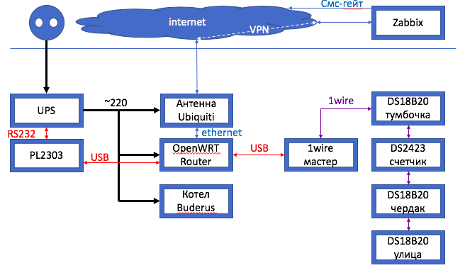
The composition of the complex at the moment
- UPS Energy PN-750 + 100 Ah battery
- USB-> RS232 converter based on PL2303
- Router Tp-link tl-wr1043nd +
- 1wire network master based on a purchased USB thermometer DS18B20 + PL-2303TA
- 1wire 3 sensors DS18B20
- 1wire radioseti DS2423 water meter module
A virtual machine with a Zabbix server outside the home network.
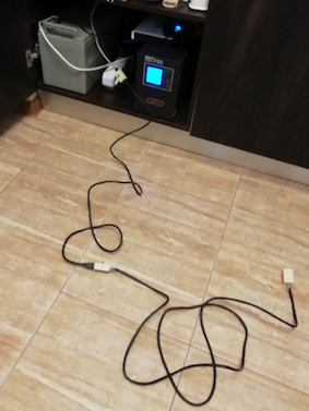
Stage 1. Preparation of infrastructure
The first step was the question of physical reorganization: the router was moved to the nightstand near the vent mine, where UPS was planned to be installed further. The antenna to the Internet provider Ubiquiti Nanostation Loco M2 PoE was connected to the same outlet as the router, in order to continue to be powered by UPS.
I already had a dedicated installation of Zabbix on a remote server and some experience working with this application, so with the theory of organizing alert-ting, and even the dashboard itself, no problems were expected.
The router is flashed in OpenWRT Chaos Calmer, a VPN is configured to the network where the Zabbix server was located.
I immediately added the metrics to zabbix, having obtained the item template for openwrt. Thus, I got the opportunity to monitor both the system and, for example, how many and which MAC addresses are connected to the point. What in the future should have served as a decision on the shutoff of water in the house.
Step 2. Choosing a UPS
The selection criteria were:
- the possibility of a gas boiler (buderus)
- from 5 hours of boiler autonomy + Internet equipment
- presence of a monitoring interface
- low noise (placement - bedside table in the kitchen near the vent shaft)
- due to restrictions on placement and price - preferably a single-battery design
We will examine the possibility of meeting the criteria in order.
The ability of the gas boiler to work is explained by the fact that the boiler requires a clean sine, otherwise the pump motor will buzz and wear out. About this you can google a lot of articles.
Ordinary (computer UPS) do not give such a sine, giving out an approximated sine wave.
The second important factor is the presence of “through neutral”. Everything is a little more complicated here, but it’s also easy to google, so I won’t stop. I can only say one thing: without a through neutral, buderus did not work, or rather it fell into error, because the ionization sensor did not work and the boiler simply did not see a flame.
As a substitute for UPS, there was a shift in focus towards online and line-interactive UPS.
From 5 hours of boiler autonomy + Internet equipmentgive mostly UPS with an external battery. Due to location and price restrictions, a single-battery design is desirable . The 100Ah battery was supposed to last for 8+ hours.
The presence of a monitoring interface to at least know when the system switched to the battery, in order to go home in winter and start the generator. I had no particular requirements here (as well as implementation experience). I was looking for everything that comes with rs232 or usb interface.
The requirement of a low noise level actually turned out to be a serious limitation and discarded a whole class of equipment - online UPS, since they all work in the constant ventilation mode of the transformer (the fan does not turn off).
Calling the Energy store, I got the last PN-750 with rs232 from the storefront. Cheap enough, since there were no wires in the kit.
Stage 3: UPS Setup
There are problems connecting the UPS. I bought several USB-> RS232 converters, read on the forums that energy uses the standard Megatec protocol and you can at least work with it through the Upsilon2000 software. But no matter how much I struggled, there was complete silence on the serial interface. After a week of ordeals, I decided to disassemble the UPS and see what was there, spit on the warranty. The problem turned out to be commonplace - the RS232 board was not connected to the UPS main board, and the connector was slightly broken. I replaced the connector, connected it and about a miracle, everything took off, although the firmware gave out the strange name UPS - SIN800 (it seems now I understand why the energy in the new models was cut by rs232).
Under OpenWRT, there was a standard P / O for working with UPS: network ups tools, which has everything you need to display metrics in the console.
root@OpenWrt:/# upsc myups@127.0.0.1
battery.charge: 100
battery.voltage: 13.32
battery.voltage.high: 13.00
battery.voltage.low: 10.40
battery.voltage.nominal: 12.0
device.mfr: GERMANY
device.model: SIN 800S
device.type: ups
driver.name: blazer_ser
driver.parameter.cablepower: both
driver.parameter.pollinterval: 2
driver.parameter.port: /dev/ttyUSB0
driver.parameter.protocol: megatec
driver.version: 2.6.5
driver.version.internal: 1.55
input.current.nominal: 2.7
input.frequency: 50.0
input.frequency.nominal: 50
input.voltage: 225.7
input.voltage.fault: 225.7
input.voltage.nominal: 220
output.voltage: 219.6
ups.beeper.status: enabled
ups.delay.shutdown: 30
ups.delay.start: 180
ups.firmware: Z1911F100
ups.load: 5
ups.mfr: GERMANY
ups.model: SIN 800S
ups.status: OL
ups.temperature: 48.0
ups.type: online
And the most interesting is that under Zabbix there is a ready-made template for nut. Vobschem - we are sawing into the zabbix-agent the shell script from the tempate kit and we have a beautiful picture in zabbix in dynamics. Task 1 and 2 at this stage was solved (and the idea of monitoring the total energy consumption appeared in the future).
Stage 4: 1wire and temperature
Some time ago I bought a USB thermometer on ebay (a combined converter board and a sensor).
OpenWRT also turned out to be suitable software, the utility digitemp_DS9097. She displayed the temperature of a single soldered sensor. Having read that there is 1wire, I realized that you can try not to be limited to one sensor and pick up a whole sensor bus to the purchased USB converter. Having taken several DS18B20 microcircuits and “barrels” under a twisted pair in the store, I built a construct with the sensor removed outside the barrel and connected internally with 3 wires.
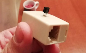
I have known about this design for many years, we used this to take readings in data centers, but then I still did not know about 1wire. When connecting the barrels to each other with standard patch cords and switching this farm to a “USB thermometer”, I got the values from all 3 temperature sensors.
It remains to throw them around the locations. The total length of the tire was about 30 meters. The signal does not disappear. A barrel placed on the street is filled with a glue gun. Lived the winter.
Stage 5: water
I had to change the water meter at the entrance (it was not a pulse, without a reed switch). Thanks to life in a country house, plumbing does not cause questions. I bought it at the nearest plumbing store and replaced it. In the new meter, one pulse occurs every 10 liters of water. Now these impulses need to be considered something.
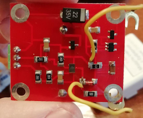
For some reason, they discontinued an interesting digital-counter microcircuit - DS2423. But it turned out that the guys from Volgograd (radioseti) have a ready-made device that, thanks to the built-in battery, also counts the value of the number of pulses in the event of a power outage. However, the device itself was adapted to its own network architecture. From RJ-11 connectors to a separate 12V power supply. In my case, I wanted to limit myself to powering the existing bus (5V). I had to get around the "extra" strapping and solder directly to the conclusions of the DS2423 directly. Then the device worked, the register values became visible on the bus. There are two of them, the device implies connecting to two water meters at the same time - hot water and hot water. I have only one water input, so I use the second register only for tests.
The end result for 1wire topology:
root@OpenWrt:/etc/zabbix# digitemp_DS9097 -c /etc/digitemp.conf -a
DigiTemp v3.5.0 Copyright 1996-2007 by Brian C. Lane
GNU Public License v2.0 - http://www.digitemp.com
Apr 04 16:16:35 Sensor 0 C: 29.81 F: 85.66
Apr 04 16:16:36 Sensor 1 C: 14.00 F: 57.20
Apr 04 16:16:37 Sensor 2 C: 6.56 F: 43.81
Apr 04 16:16:37 Sensor 3 #0 6609
Apr 04 16:16:37 Sensor 3 #1 9
By the way, since a new water meter was installed simultaneously with a digital pulse meter, we can draw conclusions about the discrepancy of readings / bounce of contacts. Visually, these discrepancies are almost absent (up to several hundred liters at the current reading of 60,000).
Stage 6: Alert
Using the information collected, it was possible to make useful alerts:
- outdoor temperature in sms every morning (+ sensor participation in narodmon project)
- UPS Battery Transfer Message
- UPS battery low
- low / high voltage message
- a message about the heat in the nightstand with the equipment
- report of low temperature in the attic (tomato rescue)
- message about the "alien / new" mac address on the network
- message about high water consumption (within a certain time)
Stage 7: the future
A digital gauge was purchased on aliexpress with an rs232 output in the form of USB. But while he did not fight with him, he does not respond to packets. We will think further. I hope to squeeze.
I plan to purchase a ball valve control relay (the valve itself already exists) for remote control of the valve and the possible implementation of automatic shut-off of water in the absence of a home.
Somehow to integrate the gallus digital gas meter into the circuit to notify of a running deposit.
Finally, a few graphs: