The departure of an electronic engineer from Apple caused a stir among stock speculators. How to become like him?
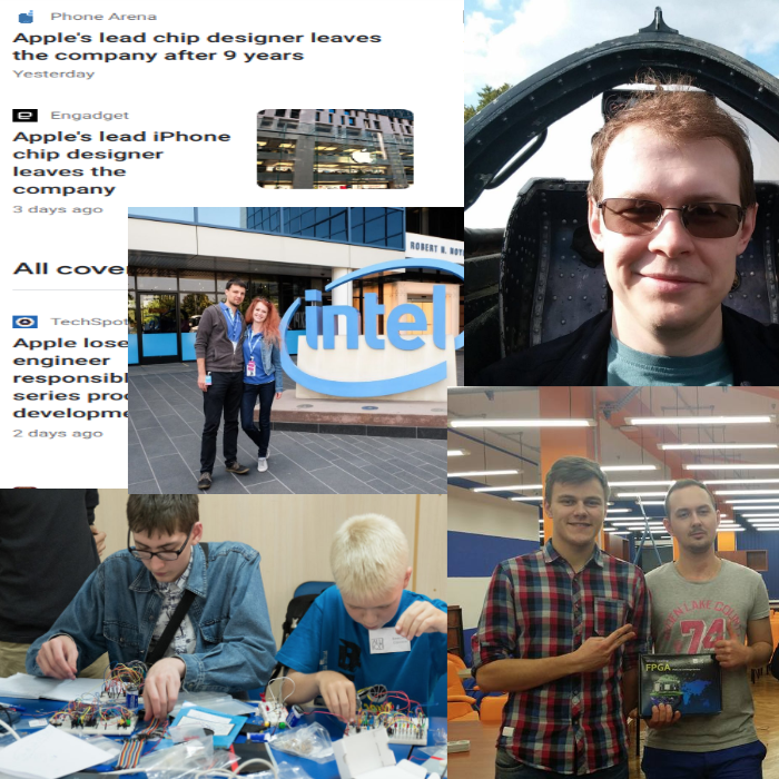
March 29, an engineer named Gerard Williams III resigned from Apple. This news was immediately published by CNET and three dozen other publications around the world, not only technical, but also financial. What did this engineer do that his departure caused excitement among stock speculators? He had been designing processors in the Apple iPhone for 9 years, before that he had been working in ARM for 12 years, before that he had been designing DSP in Texas Instruments, and before that he had been developing FPGA circuits in Intel. In all places he used design technology at the level of register transfers, using Verilog and VHDL hardware description languages.
Examples closer to Russia? In the photo on the right: the 25-year-old Muscovite Ilya Neganov took the book Harris & Harris in 2011 (the latest version of which can be downloaded here or here), designed a simple processor, now works at Apple, designs on a GPU veril, flies on an airplane on weekends. Below are a couple of newlyweds from St. Petersburg, who designed on-vertex and FPGA camera image processing and received a prize at the Innovate FPGA contest. They spent their honeymoon at Intel's headquarters in Santa Clara. Further comrades from Kiev, two of whom won bronze at the European Innovate FPGA final. And finally, two schoolchildren, from grades 5 and 9, who do their first exercises with microcircuits of small degree of integration on the breadboard, and then proceed to exercises on the veril and FPGA.
These are five points on the trajectory from the student to Gerard Williams the Third. The trajectory is quite heavy, since the initial barrier to entering the design of digital microcircuits is higher than to entering programming. In this post we will talk about how to facilitate the initial section of the trajectory for Russian and other students.
In these two weeks, a group of colleagues from RUSNANO, Wave Computing, MIET, IVA Technologies, HSE MIEM, Amperka, Publishing House DMK-Press holds the following event: First, students take a theoretical online course (parts from transistor to microcircuit , “The logical side of the digital circuitry " , " The physical side of digital circuitry "), on which they get acquainted with the so-called RTL2GDSII route - a group of technologies that engineers at electronic companies use to design chips. Then we conduct practical classes with FPGA reconfigurable logic circuits . In this way, for example, he teaches MIT in the course 6.111, but we try it in a very basic form for schoolchildren of the olympiad type.
The theoretical course is important so as not to waste time on the practical course to explain the design theory at the level of register transfers, but simply spend three evenings two hours playing with FPGA cards, which you can then take with you. Also, a theoretical course links FPGA exercises to mass products that use ASIC chips.
The practical course will be another experiment (the previous ones were conducted by different teachers in Nizhny Novgorod, Kiev, Alma-Ata, Kazakhstan, Minsk, Novosibirsk, Tomsk and Irkutsk) to find out how to make exercises with Verilog and FPGA interesting and useful for beginners.
Is it worth doing exercises with FPGAs with microcircuits with a small degree of integration? There are different opinions on this score: Ilya Kudryavtsev, Dean of the Samara University, believes that it’s not worth it, it’s better to immediately give the latest technology in 2019, rather than the ancient CMOS 4000 on a breadboard that were relevant 50 years ago. Stanislav Zhelnio, a neurochip design engineer at IVA Technologies, believes that it is worth it, because otherwise students perceive FPGAs as another microcontroller such as Arduino, but simply with a strange programming language Verilog. In fact, a student or school student should immediately clearly realize that the verilogue describes the scheme, not the program (the chain of instructions), and exercises with the CMOS 4000 help to settle the correct image in the brain.
If you write on Verilog, as if it were a program, not a circuit, then the code will work on the simulator, but will not be synthesized, and even if it is synthesized, you will get a crazy (in terms of timing or size) scheme.
Therefore, one of the approaches looks like this: to design the circuit on microcircuits of a small degree of integration (counters, shift registers, adders, decoders), then repeat it on a verilogue, synthesize and register it in the FPGA.
Some say: why not draw a diagram for the FPGA with the mouse on the screen (schematic entry) and enter it into the FPGA before doing exercises on the veril? The mouse approach has three drawbacks:
Yes, CMOS 4000 and 74XX were out of date in the 1970s, they were replaced by PAL, GAL, PLD, then integrated chips. Therefore, in the 1970s they were used in mugs for children, and in the 1980s they went out of fashion, because they stopped paying salaries for their ability to use them, but no one has since come up with how to more clearly demonstrate, for example, the D-trigger function, therefore as a prequel to FPGA / FPGA they can be applied. MIT does the same - see Lab # 1 here .
After exercises with microcircuits with a small degree of integration and their equivalents on a veril on the FPGA, you can complicate the tasks and do on one FPGA what it took dozens, hundreds or thousands of microcircuits of a small degree of integration, which I will discuss later.
Here is an example of combinational logic, a priority encoder, on microcircuits with a small degree of integration:
And here is what this priority encoder looks like in Verilog hardware description language:
Here is an example of sequential logic, a shift register, on microcircuits with a small degree of integration:
And here is what this shift register looks like on a verilogue :

Here is how the synthesis process looks from the hardware description languages and flashing the circuit into reconfigurable FPGA logic:
After such simple exercises, students can design circuits that communicate via SPI, I2C, UART with light sensors, compasses, keyboards, produce sound and even pictures on VGA. Here is a unique fifth grader Vyacheslav combined a light sensor with a sound generator on an FPGA board:
Code for the module receiving data from the light sensor that Vyacheslav used.
A book has recently been released on working with a VGA display with FPGA, which should be translated into Russian for summer camps such as the Novosibirsk LSHUP or the future camp in Zelenograd MIET.

Other convenient exercises for beginners are a snake on a 7-segment indicator, figures on an LED matrix, 4x4 keyboard input, note generation (digital organ), state machines for pattern recognition (code lock).
Mathematically-oriented students can try to make a stack calculator , devices for calculating the square root, a systolic array for a neural calculator, or implement examples from Hacker's Delight in a hardware .
Quite advanced students can develop simple processors with pipelines, interrupts, caches, etc. Here’s Arseny’s ninth grader with an FPGA body and Dasha’s ninth grader with a schoolMIPS processor modification .
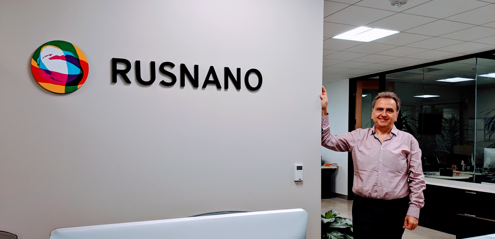
In fact, for the sake of such advanced students, RUSNANO helped organize an online course and practical classes on April 17-19 in Moscow . The eNANO educational department worked on this, and the RUSNANO California branch RUSNANO USA helped a bit. His office is located right in the world center of venture capital, at 3000 Sand Hill Road in Menlo Park. The founders of Apple, Google and Amazon came to Sand Hill Road for money.
RUSNANO has invested billions of rubles in the Russian microelectronic projects ELVIS-NeoTek and Baikal Electronics. It is expected that today's students will get acquainted with the basics of RTL2GDSII, then study at universities such as MIPT, MIET or ITMO, become specialists in the class of Gerard Williams the Third, and then RUSNANO will invest in their projects.
Examples closer to Russia? In the photo on the right: the 25-year-old Muscovite Ilya Neganov took the book Harris & Harris in 2011 (the latest version of which can be downloaded here or here), designed a simple processor, now works at Apple, designs on a GPU veril, flies on an airplane on weekends. Below are a couple of newlyweds from St. Petersburg, who designed on-vertex and FPGA camera image processing and received a prize at the Innovate FPGA contest. They spent their honeymoon at Intel's headquarters in Santa Clara. Further comrades from Kiev, two of whom won bronze at the European Innovate FPGA final. And finally, two schoolchildren, from grades 5 and 9, who do their first exercises with microcircuits of small degree of integration on the breadboard, and then proceed to exercises on the veril and FPGA.
These are five points on the trajectory from the student to Gerard Williams the Third. The trajectory is quite heavy, since the initial barrier to entering the design of digital microcircuits is higher than to entering programming. In this post we will talk about how to facilitate the initial section of the trajectory for Russian and other students.
In these two weeks, a group of colleagues from RUSNANO, Wave Computing, MIET, IVA Technologies, HSE MIEM, Amperka, Publishing House DMK-Press holds the following event: First, students take a theoretical online course (parts from transistor to microcircuit , “The logical side of the digital circuitry " , " The physical side of digital circuitry "), on which they get acquainted with the so-called RTL2GDSII route - a group of technologies that engineers at electronic companies use to design chips. Then we conduct practical classes with FPGA reconfigurable logic circuits . In this way, for example, he teaches MIT in the course 6.111, but we try it in a very basic form for schoolchildren of the olympiad type.
The theoretical course is important so as not to waste time on the practical course to explain the design theory at the level of register transfers, but simply spend three evenings two hours playing with FPGA cards, which you can then take with you. Also, a theoretical course links FPGA exercises to mass products that use ASIC chips.
The practical course will be another experiment (the previous ones were conducted by different teachers in Nizhny Novgorod, Kiev, Alma-Ata, Kazakhstan, Minsk, Novosibirsk, Tomsk and Irkutsk) to find out how to make exercises with Verilog and FPGA interesting and useful for beginners.
Is it worth doing exercises with FPGAs with microcircuits with a small degree of integration? There are different opinions on this score: Ilya Kudryavtsev, Dean of the Samara University, believes that it’s not worth it, it’s better to immediately give the latest technology in 2019, rather than the ancient CMOS 4000 on a breadboard that were relevant 50 years ago. Stanislav Zhelnio, a neurochip design engineer at IVA Technologies, believes that it is worth it, because otherwise students perceive FPGAs as another microcontroller such as Arduino, but simply with a strange programming language Verilog. In fact, a student or school student should immediately clearly realize that the verilogue describes the scheme, not the program (the chain of instructions), and exercises with the CMOS 4000 help to settle the correct image in the brain.
If you write on Verilog, as if it were a program, not a circuit, then the code will work on the simulator, but will not be synthesized, and even if it is synthesized, you will get a crazy (in terms of timing or size) scheme.
Therefore, one of the approaches looks like this: to design the circuit on microcircuits of a small degree of integration (counters, shift registers, adders, decoders), then repeat it on a verilogue, synthesize and register it in the FPGA.
Some say: why not draw a diagram for the FPGA with the mouse on the screen (schematic entry) and enter it into the FPGA before doing exercises on the veril? The mouse approach has three drawbacks:
- It requires learning software, which takes longer than just sticking components into a breadboard.
- The experience of a burnt out LED or floating input without a pull-up resistor on a breadboard is more valuable than the sterile experience in a schematic entry.
- Digital logic designers have not used a schematic entry since the early 1990s; everyone writes on veril, sometimes on VHDL.
Yes, CMOS 4000 and 74XX were out of date in the 1970s, they were replaced by PAL, GAL, PLD, then integrated chips. Therefore, in the 1970s they were used in mugs for children, and in the 1980s they went out of fashion, because they stopped paying salaries for their ability to use them, but no one has since come up with how to more clearly demonstrate, for example, the D-trigger function, therefore as a prequel to FPGA / FPGA they can be applied. MIT does the same - see Lab # 1 here .
After exercises with microcircuits with a small degree of integration and their equivalents on a veril on the FPGA, you can complicate the tasks and do on one FPGA what it took dozens, hundreds or thousands of microcircuits of a small degree of integration, which I will discuss later.
Here is an example of combinational logic, a priority encoder, on microcircuits with a small degree of integration:
And here is what this priority encoder looks like in Verilog hardware description language:
module priority_encoder
(
    input      [2:0] in,
    output reg [1:0] out
);
    always @*
    begin
        casez (in)
            3'b1??  : out = 2'd1;
            3'b01?  : out = 2'd2;
            3'b001  : out = 2'd3;
            default : out = 2'd0;
        endcase
    end
endmodule
Here is an example of sequential logic, a shift register, on microcircuits with a small degree of integration:
And here is what this shift register looks like on a verilogue :
Here is how the synthesis process looks from the hardware description languages and flashing the circuit into reconfigurable FPGA logic:
After such simple exercises, students can design circuits that communicate via SPI, I2C, UART with light sensors, compasses, keyboards, produce sound and even pictures on VGA. Here is a unique fifth grader Vyacheslav combined a light sensor with a sound generator on an FPGA board:
Code for the module receiving data from the light sensor that Vyacheslav used.
A book has recently been released on working with a VGA display with FPGA, which should be translated into Russian for summer camps such as the Novosibirsk LSHUP or the future camp in Zelenograd MIET.
Other convenient exercises for beginners are a snake on a 7-segment indicator, figures on an LED matrix, 4x4 keyboard input, note generation (digital organ), state machines for pattern recognition (code lock).
Mathematically-oriented students can try to make a stack calculator , devices for calculating the square root, a systolic array for a neural calculator, or implement examples from Hacker's Delight in a hardware .
Quite advanced students can develop simple processors with pipelines, interrupts, caches, etc. Here’s Arseny’s ninth grader with an FPGA body and Dasha’s ninth grader with a schoolMIPS processor modification .
In fact, for the sake of such advanced students, RUSNANO helped organize an online course and practical classes on April 17-19 in Moscow . The eNANO educational department worked on this, and the RUSNANO California branch RUSNANO USA helped a bit. His office is located right in the world center of venture capital, at 3000 Sand Hill Road in Menlo Park. The founders of Apple, Google and Amazon came to Sand Hill Road for money.
RUSNANO has invested billions of rubles in the Russian microelectronic projects ELVIS-NeoTek and Baikal Electronics. It is expected that today's students will get acquainted with the basics of RTL2GDSII, then study at universities such as MIPT, MIET or ITMO, become specialists in the class of Gerard Williams the Third, and then RUSNANO will invest in their projects.