PTZ camera parsing: what's inside and how it works
Today we are preparing a PTZ camera and in detail considering its iron components in order to understand the principle of operation.
Before we cut, let's look a little
How to make video communication comfortable enough for participants to perceive it as living? This effect can be achieved if the camera captures not only the general plan of the room, but also a specific participant. Transitions between scenes should be quick and smooth, so that communication does not cause discomfort and does not distract participants from discussing working issues.
How to achieve this? There are a couple of options:
- programmatically cut out (and, according to non-ours, sprinkle) the necessary part of the image from the general plan, which is captured by the camera;
- or install a PTZ camera. They come with mechanical or magnetic drives.
I could not find a camera with magnetic drives. But cameras with mechanics around are a dime a dozen. I also disassembled the PTZ FullHD camera model, modern and widespread in the Russian Federation, to understand how the logic and principle of work have changed over 10 years of progress and development. So let's get started!
Tandberg - HD Precision Camera TTC8-01
So, we will start with a very common PTZ camera from the Norwegian company Tandberg. It was this camera that migrated to the Cisco Telepresence line without any significant changes and was sold until the early 2010s.

At one time, Tandberg made premium PTZ cameras, and we are told about this by a strict, concise design with a predominance of metal parts of the case.
Outwardly, Tandberg looks very understandable - optics and a matrix are placed in a silver tube, and mobile mechanisms connect the camera to the base.
Zoom: 7x, optical
Matrix: 1/3 "CMOS
Minimum focal length: 0.3 m
Viewing angle: 42 0
Horizontal rotation: 180 0 (+90 0 ..- 90 0 )
Vertical tilt: 30 0 (+10 0 ..- 20 0 )
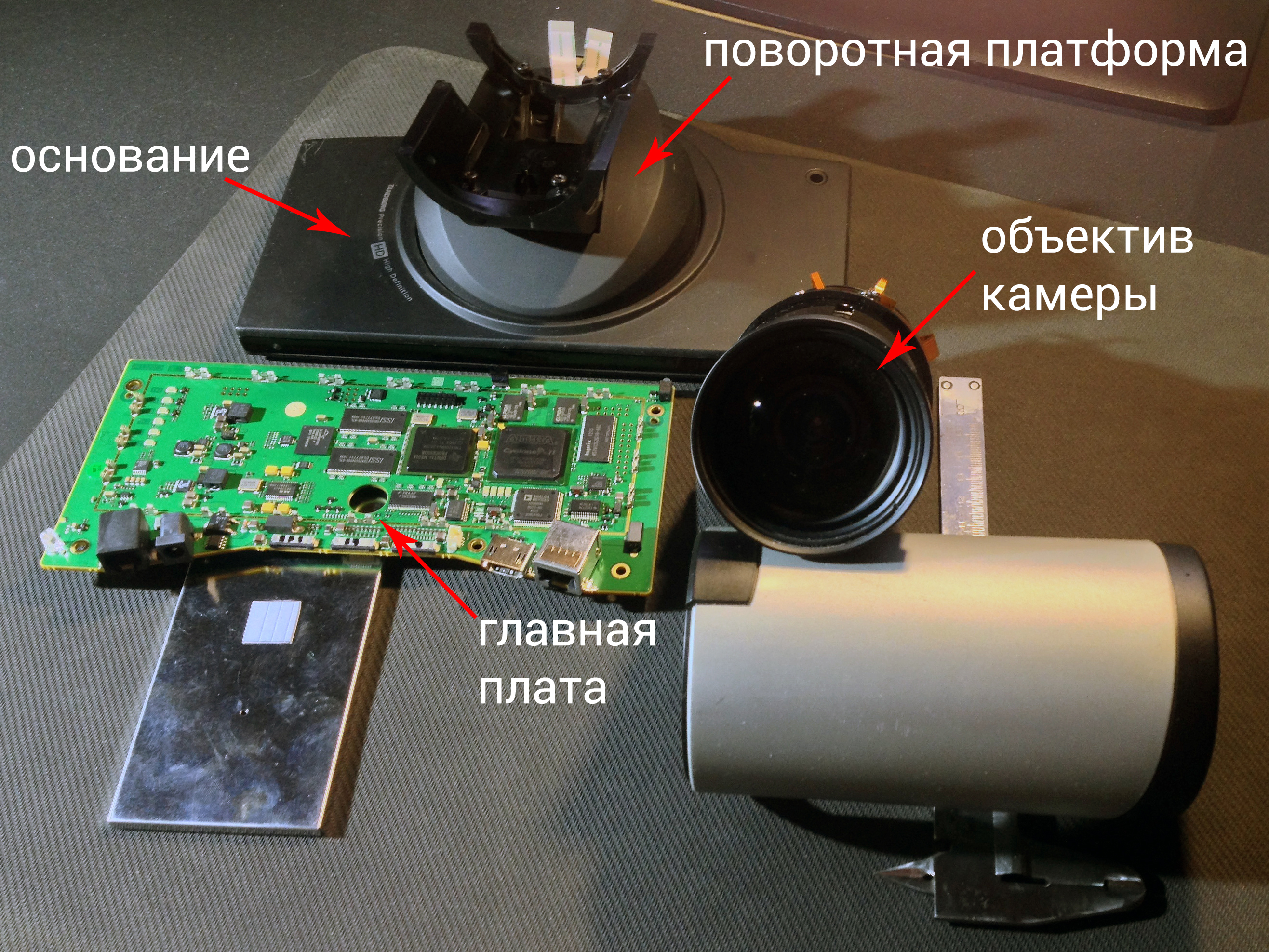
The massive metal base adds stability to the camera and reliably protects the main board with electronics from external influences. It is on this basis that the turntable is located.
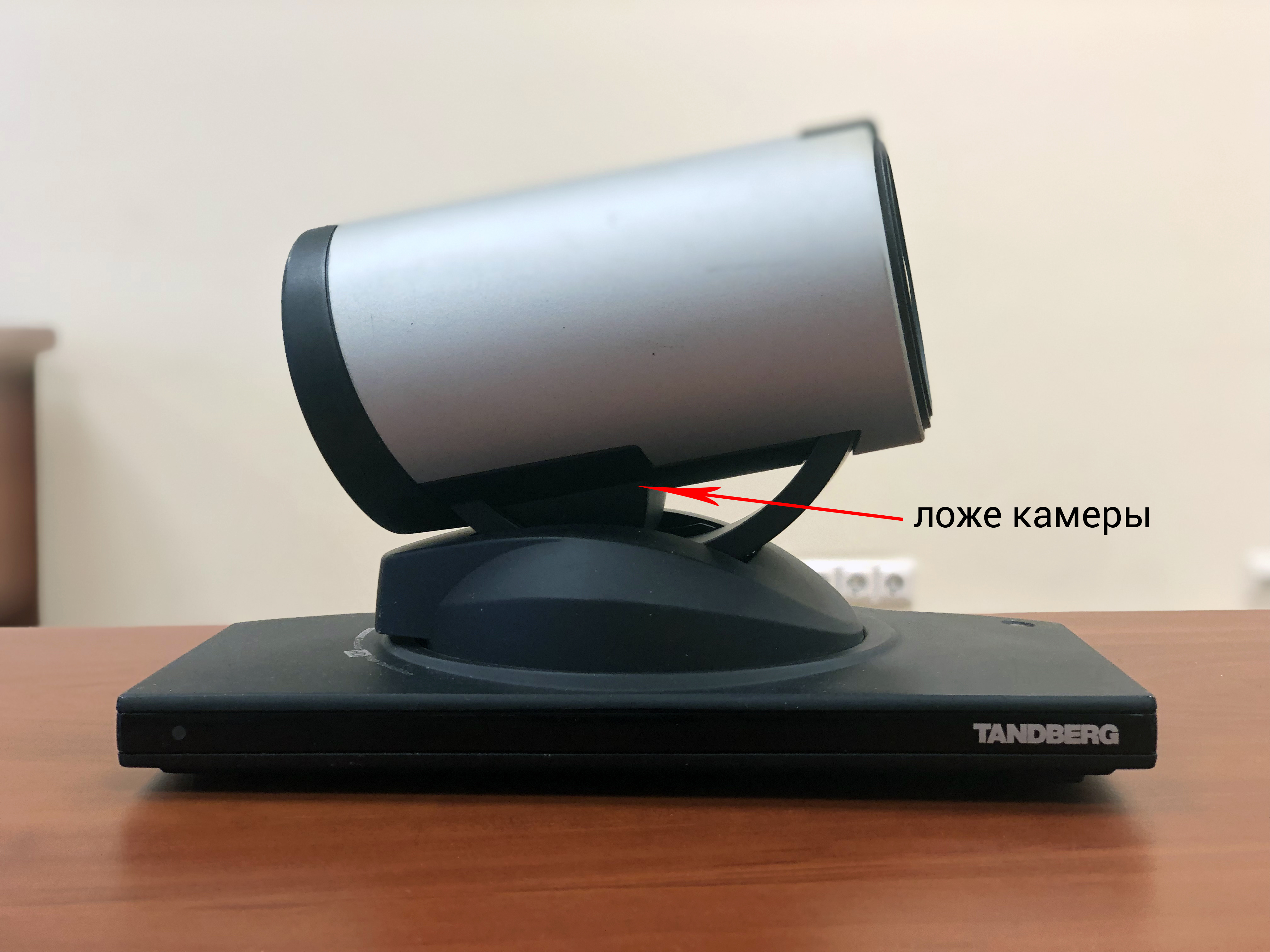
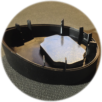
The camera bed rolls on special rollers located inside the moving platform. The operation of this mechanism resembles balancing a circus acrobat on metal cylinders.
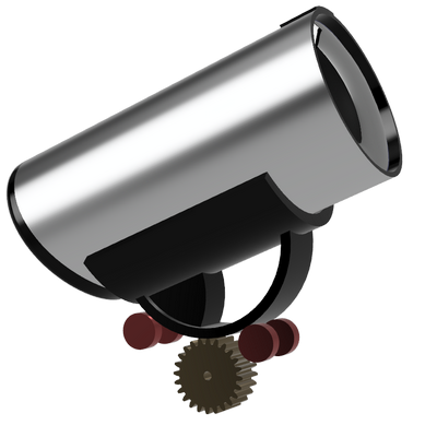
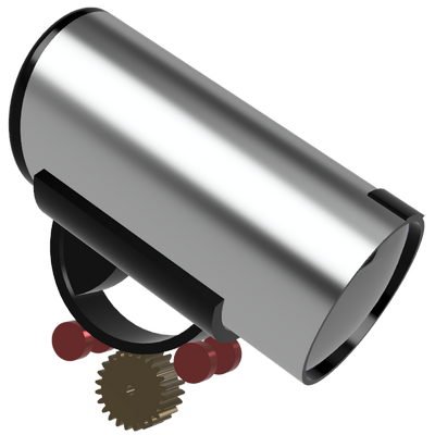
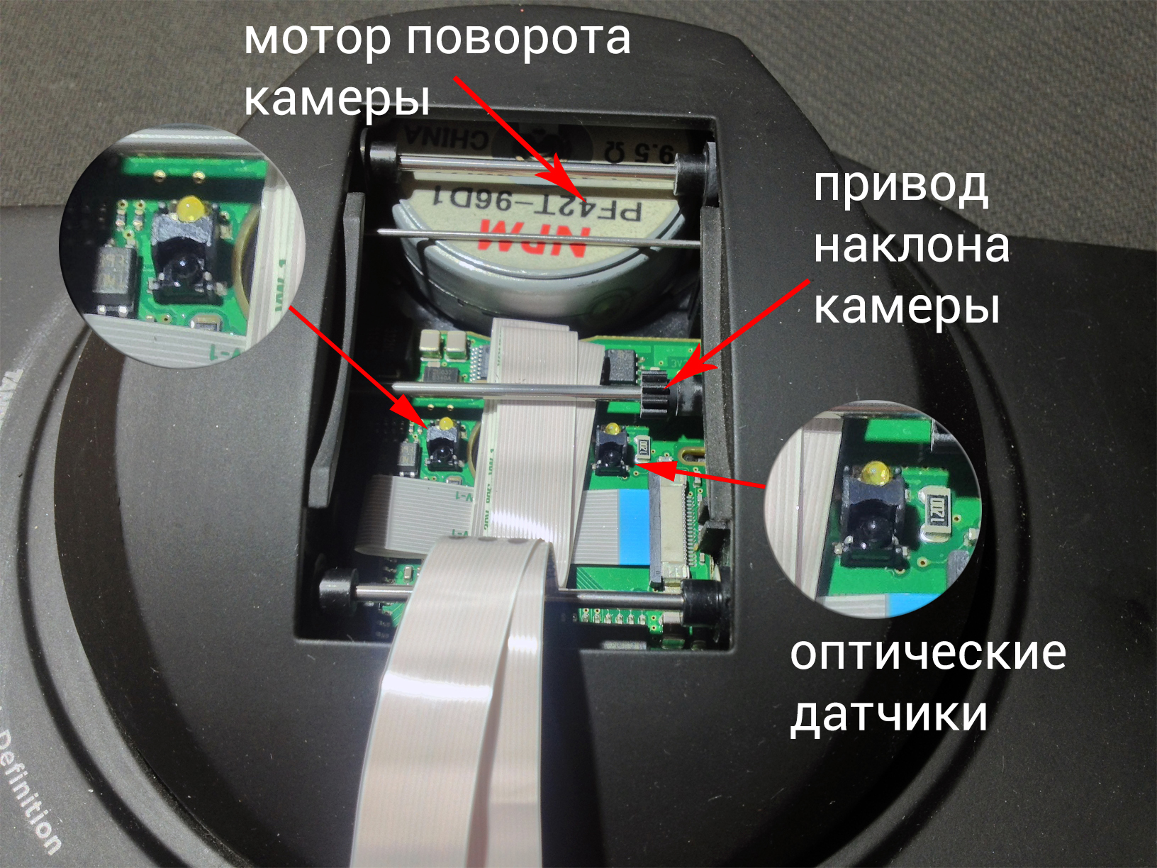
This unit is driven by an ordinary electric motor with a gear wheel, along which the chamber of the chamber rolls. To show the work of this mechanism, I had to uncover the good old Autodesk Fusion.
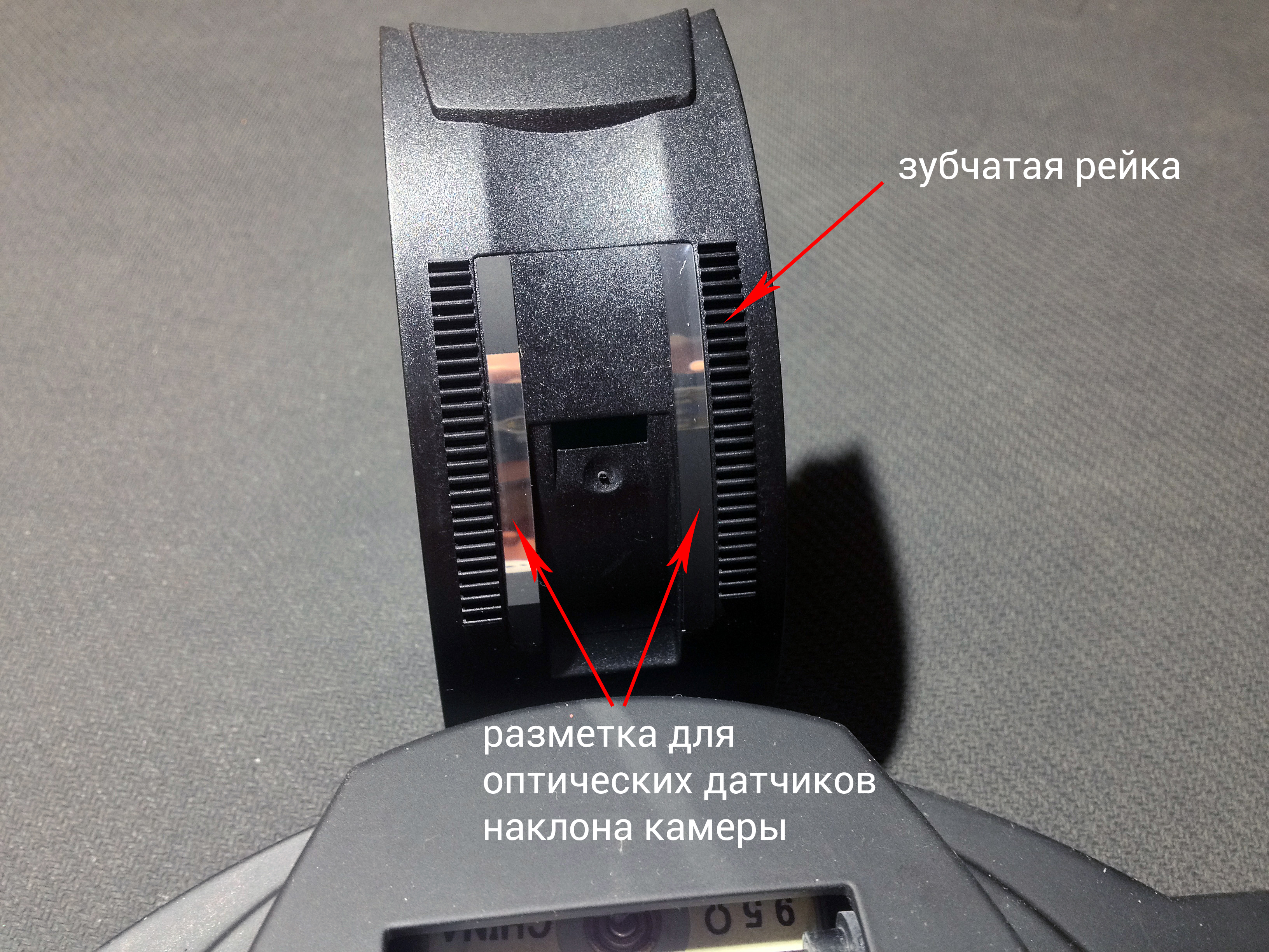
Optical sensors are called in to monitor the collector motor at each moment of time, which determine the angle of inclination from the marks from the reflected light. To do this, two special pads are installed on the inside of the gear racks, which form interruptions in reflected light, which determine the angle of the camera.
 In order for the low-power collector motor to cope with the heavy optics of the camera, the lens is balanced so that the center of gravity coincides with the axis of the motor. Massive load at the back of the camera and provides the same balance.
Under the dome is another drive motor that rotates the camera left and right. However, it is structurally different from the collector one in that the shaft is rotated in small steps (1 step = 3,750), that is, for one full revolution, 3,600 / 3,750 = 96 steps are required. An additional bonus is to keep the shaft in the set position.
To stabilize the image of the PTZ camera, there are mechanisms to maintain a given position, which means that if you direct the camera to the other side with your hands and perseverance, then the plastic parts inside the camera will fail very quickly (if not immediately).
This rule is true for a turned off camera. If you do not go into the intricacies of theoretical mechanics, then we can say that plastic gears can transmit rotation from the motor to the camera nodes, and not vice versa.
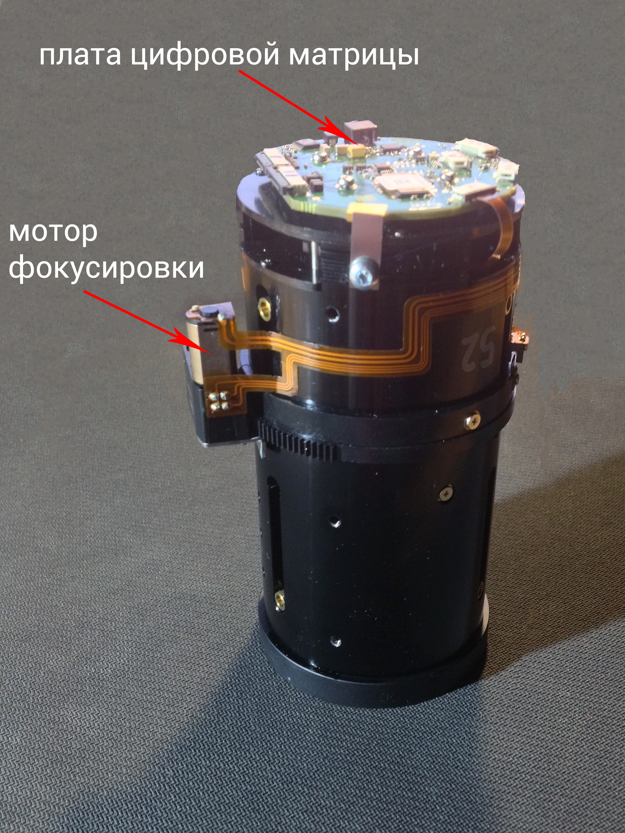
And about the most important thing - about the camera. Structurally, it looks like a reflex camera, only without a pentaprism and a mirror. The focal length is regulated by the collector motor and mechanical gears: these, of course, are not ultrasonic motors of modern “DSLRs,” but the small weight and dimensions for a stationary camera are not key indicators at all.
Electronics
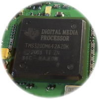 The digital signal processor from Texas Instruments with advanced computing power at the beginning of the 2000s, capable of executing almost 6 billion instructions per second, controls everything. In those days, it was an advanced solution in the SoC (System on the Chip) format, in which a multi-level L1 / L2 cache, a 64-bit interface to external RAM, 10/100 Mbps Ethernet, 3 video ports with multiple support were implemented permissions, as well as the management of other peripherals.
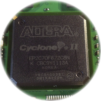 The next advanced microcircuit of its time is Altera Cyclone 2. In fact, it is an ordinary FPGA (programmable logic integrated circuit). Device manufacturers can program such circuits for any task, from controlling servo drives to transmitting memory data.
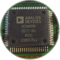 HDMI version 1.3 is implemented by the AD9889B chip, which supports FullHD (1080p) resolution with protection for transmitting media content using HDCP v technology. 1.2.
The remaining components are memory modules and passive radio components designed to operate the basic elements.
Subject No. 2: CleMic 1012w
Zoom: 12x, optical
Matrix: 1 / 2.8 ″ CMOS HD sensor
Minimum focal length: 0.3 m
Viewing angle: 72.5 0
Horizontal angle of rotation: 340 0 (+ 170 0 ..- 170 0 )
Vertical tilt: 120 0 (+90 0 ..- 30 0 )
The camera body is made entirely of plastic and has a wide and stable base. The front of the camera has IR receivers for the remote control, and the back has interface connectors. The weight of the camera is small: I suppose that it can be hung in an armstrong on the ceiling or fixed on a plasterboard partition.

The movement axes are organized much simpler and more understandable than Tandberg’s stepper motors work as a driving force, transmitting torque to the drive pulleys.
The mobile platform has 2 hollow racks, between which a camera is fixed, in the cavity of one of the racks, a drive mechanism is hidden, due to which the angle of inclination changes.
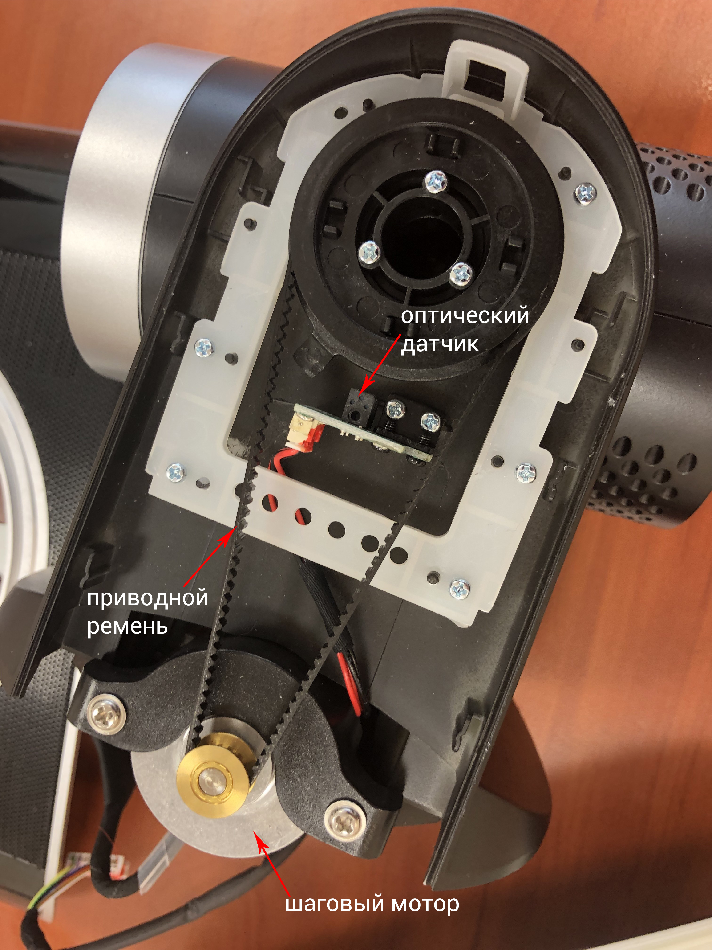
A little lower than the drive pulley is an optical sensor. This trailer is needed to determine the position of the camera after switching on.
When starting up, the lens leans down, and when a special spike interrupts the light flow in the optical sensor, the system realizes that the lowest point has been reached. All further positioning is done by counting steps.
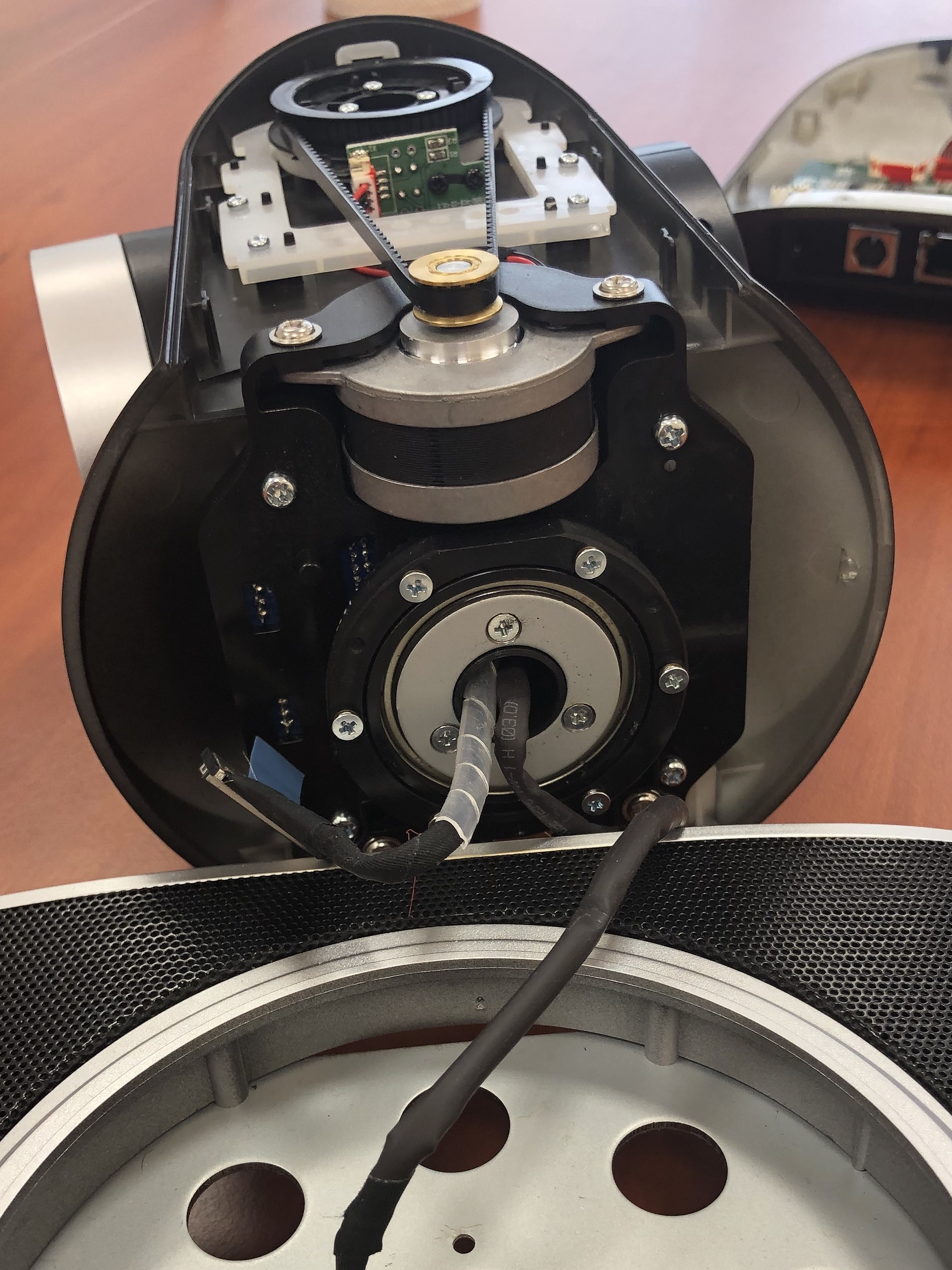
The motor, turning the camera left and right, is hidden behind the mating flange with 6 screws, equipped with the same trailer to determine the horizontal position of the camera.
Since the mating flange is stationary, in the center there are 2 cables: for controlling motors and a cable with a digital matrix.
As we can see, the mechanical transmission system consists entirely of powerful stepper motors, which makes the camera positioning more accurate and faster, and belt drives reduce the level of the device’s own noise.

The camera electronics are very similar in many ways, so we’d better talk about the obvious differences. USB3.0 and RS-232 appeared from the new ones, with the help of which you can get video in compressed form, as well as assemble a cascade of such cameras and through UART (RS232) fully automate their pointing at the conference participants.
IMHO
As you can see, a modern PTZ camera is more reliable in design, has a better sensor and is universal in connection methods, but the rest is not far from its predecessor. In addition to one - the price, which has become 5 times lower. Therefore, today we see more and more PC-equipped meeting rooms where this PTZ beast has ceased to be exotic.