Create the borders of a procedurally generated map
- Transfer
Scott Turner continues to work on his procedurally generated game and has now decided to tackle the problem of designing the borders of maps. To do this, he has to solve several difficult problems and even create his own language for describing boundaries.
Borders remained an important element of fantasy cards, which had been on my list for quite some time. Functional maps usually have a simple border line , but fantasy maps and medieval maps, of which the former often borrow ideas, have fairly thoughtful and artistic boundaries. These boundaries make it clear that the map is intentionally made fantastic, and give the viewer a sense of wonder.
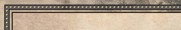
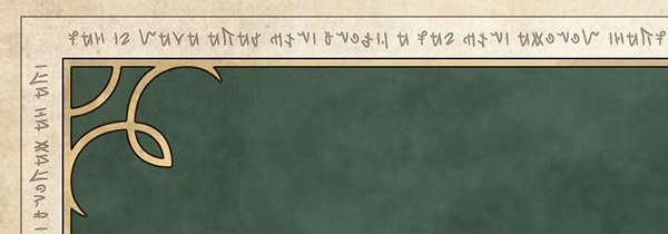
Currently in my game Dragons AboundThere are a couple of simple ways to draw borders. She can draw a single or double line around the perimeter of the map and add simple elements in the corners, as in these figures:

The game can also add a field at the bottom of the border for the name of the map. There are several variations of this field in Dragons Abound , including such complex elements as fake screw heads:
There is variability in these name fields, but they are all created manually.
One interesting aspect of the boundaries of fantasy cards is that they are both creative and template. Often they consist of a small number of simple elements that combine in different ways to create a unique result. As always, the first step when working with a new topic for me is to study a collection of map examples, create a catalog of border element types, and study their appearance.
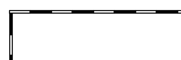
The simplest border is one line running along the edges of the map and indicating its limits. As I said above, it is also called the "frame line":
There is also a variation with the location of the borders within the map. In this version, the map reaches the edges of the image, but the border creates a virtual border inside the image:
This can be done with any type of border, but it is usually used only with simple borders like the border of a frame.
A popular fantasy card design concept is to simulate as if they were drawn on old torn parchment. Sometimes this is realized by drawing the border as the rough edge of the paper:
Here is a more sophisticated example:
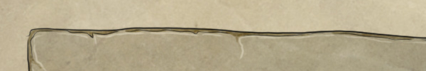
In my experience, this method has become less popular because digital tools have come into use. If you want the card to look like an old torn parchment, then it’s easier to apply the texture of the parchment to it than to draw it by hand.
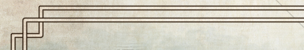
The most powerful tool in creating map borders is repeatability. In the simplest case, it is enough to repeat a single line to create two lines:
You can add interest to the map by varying the style of the repeated element, in this case by combining a thick single line with a thin single line:
Depending on the element, various style variations are possible. In this example, the line repeats, but the color changes:

To create more complex patterns, you can use “repeatable repeatability”. This border consists of approximately five single lines with different widths and distances:
This border repeats the lines, but separates them so that they look like two separate thin borders. In this part of the post I will not talk about the processing of angles, but different angles for the two lines also help in creating this difference.
Are these two lines, four, or six? I think it all depends on how you draw them!
Another element of stylization is filling the space between elements with color, pattern or texture. In this example, the border became more interesting due to the accent color filling between the two lines:
Here is an example of how the border is filled with a pattern:
Also, elements can be styled so that they look three-dimensional. Here is a map in which the border is shaded so that it looks voluminous:
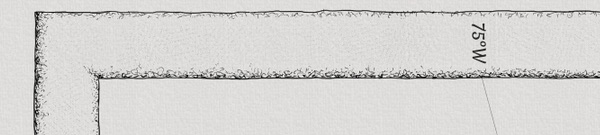
In this map, the border is shaded to look three-dimensional, and this is combined with the location of the borders inside the edges of the map:

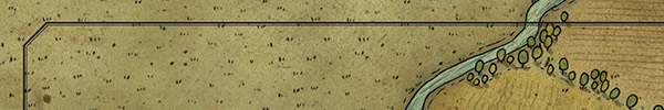
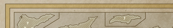
Another common border element is the scale in the form of multi-colored stripes:

These stripes form a grid ( cartographic grid ). On real maps, scale helps determine distances, but on fantasy maps it is mainly a decorative element.
These stripes are usually drawn in black and white, but sometimes red or some other color is added:

This element can also be combined with others, as in this example with lines and scale:

This example is a bit unusual. Usually the scale (if any) is the innermost element of the border.
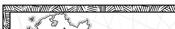
On this map, there are different scales with different resolutions (as well as strange runic notes!):
(On Reddit, user AbouBenAdhem told me that runic marks are numbers 48 and 47 written in Babylonian cuneiform. In addition, “scales with different resolutions” have six divisions divided into ten smaller divisions, which corresponds to the Babylonian hexadecimal number system. Usually I quote the source card, but in this post too many small pieces, so I did not bother. However, this map was created by Ray Thomas for author SE Boleyn, so perhaps, the action in his books takes place in the entourage of Babylon.)
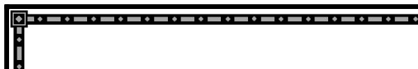
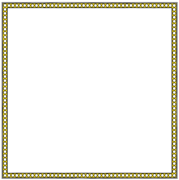
Cro e lines and scale the most common element is a repeating geometric pattern. Often it consists of parts such as circles, rhombuses and rectangles:
Geometric elements, like lines, can be shaded to make them look three-dimensional:
Complex boundaries can be created by combining these elements in different ways. Here is the border that combines lines, geometric patterns, and scale:

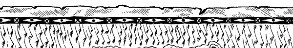
The examples shown above were digital cards, but, of course, the same thing can be done with handwritten cards. Here is an example of a simple geometric pattern created by hand:

These elements can also be flexibly combined in many ways. Here is a geometric pattern combined with a “ragged edge”:
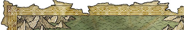
In the examples shown above, the geometric pattern is quite simple. But you can create very complex patterns by combining in a different way the basic geometric elements:

Another popular element of the pattern is weaving or Celtic knot:

Here is a more complex wicker border containing color, scale, and other elements:

On this map, weaving is combined with a ragged edge element:
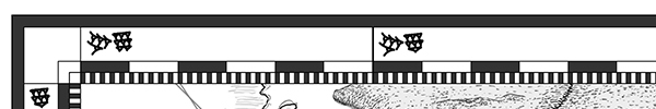
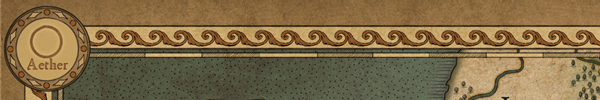
In addition to geometric patterns and weaving, any repeating pattern can be part of the border of the card. Here is an example using shapes resembling arrowheads:

And here is an example with a repeating wave pattern:
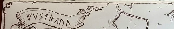
And finally, runes or other elements of the fantasy alphabet are sometimes added to the edges of fantasy cards:
The above examples are taken from modern fantasy maps, but here is an example of a historical (18th century) map with lines and a hand-drawn pattern:

Of course, you can find examples of maps with many other elements on the borders. Some of the most beautiful are completely hand-drawn and have such carefully crafted decorations that they can surpass the card itself ( World of Alma , Francesca Baerald):

It's also worth a little talk about symmetry . Like repeatability, symmetry is a powerful tool, and map borders are usually symmetrical or have symmetrical elements.
Many map borders are symmetrical from the inside out, as in this example:
Here, the border is composed of several lines with and without fill, but from the outside inward it ideally repeats relative to the center of the border.
In this more complex example, the border is symmetrical, with the exception of alternating black and white stripes of scale:
Since duplicating the scale does not make sense, it is often considered a separate element, even if the rest of the border is symmetrical.
In addition to internal-external symmetry, borders are often re-symmetrical along their length. Some illustrated borders may have a simple design that spans the entire length of the edge of the map, but in most cases the pattern is quite short and repeats, filling the border from one corner to another:
Notice that in this example the pattern contains an element that is not symmetrical (from left to right), but the general pattern is symmetrical and repeats:
One notable exception to this rule is borders filled with runes or alphabetic characters. Often they turn out to be unique, as if some long message was written along the border:
Of course, there are many other examples of map border elements that I have not considered here, but we already have a good reference point. In the next few parts, I will develop several functions in Dragons Abound for describing, displaying, and procedurally generating map borders similar to these examples. In the second part, we will start by setting the language for describing the borders of the maps.
Part 2
In this part, I will create the initial version of the Map Border Description Language (MBDL).
Why spend time creating a map boundary description language? Firstly, this will be the goal of my procedural generation. Later I will write an algorithm for creating new map borders, and the output of this algorithm will be a description of the new border on MBDL. Secondly, MBDL will serve as a textual representation of map boundaries. In particular, I need to be able to save and reuse my boundaries. To do this, I need a text notation that can be written and used to recreate the border of the map.
I will start creating MBDL by defining the simplest element: the line. The line has color and width. Therefore, in MBDL I will present the line in this form:
L(width, color)Here are some examples (sorry for my Photoshop skills):

The sequence of elements is rendered from the outside to the inside (*), so we assume that this is the border on top of the map:
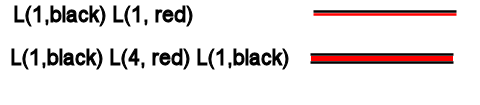
Look at the second example - a line with borders is represented as three separate line elements.
(* Drawing from the outside to the inside was an arbitrary choice - it just seemed to me that it was more natural than rendering from the inside to the outside. Unfortunately, as it turned out much later, there was a good reason to work in the opposite direction. Soon I will tell you about it, but everything is left in the post - old, because it would take a lot of time to redo all the illustrations)
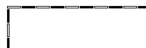
Conveniently, spaces can be represented as lines without color:

But it would be more visual to have a specific vertical space element:
VS (width)
The following simple elements are geometric shapes: stripes, rhombuses and ellipses. It is assumed that the lines are stretched over the entire length of the border, so they do not have an explicitly specified length. But geometrical figures cannot fill the whole line, therefore, in addition to the width (*), each must have a length, outline color, outline width and fill color:
B(width, length, outline, outline width, fill)

D(width, length, outline, outline width, fill)

E(width, length, outline, outline width, fill)
(* I accepted that I will consider the width in the direction from outside to inside, and the length is measured along the border.)
Here are examples of simple geometric shapes:

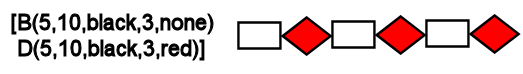
For these elements to fill the entire length of the border, they must be repeated. To indicate the group of elements that will be repeated to fill the length of the border, I use square brackets:
[ element element element ... ]Here is an example of a repeating pattern of rectangles and rhombuses:
Sometimes I will need a (horizontal) space between elements of a repeating pattern. Although you can use an element without colors to create a space, it will be smarter and more convenient to have a horizontal space element:
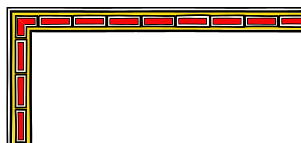
HS(length)The last function needed for this first iteration of MBDL is the ability to stack elements on top of each other. Here is an example border:
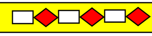
The easiest way to describe it is a wide yellow line under the upper pattern. You can implement this in different ways (for example, a negative vertical space), but I decided to use curly braces to indicate the order of the elements inward:
{element element element ...}In fact, this entry tells you to remember where the pattern was from the outside inward when entering the brackets, and then return to this point when leaving the brackets. Brackets can also be considered as a description of elements occupying a vertical space. Therefore, the border shown above can be described as follows:
L(1, black)

{L(20, yellow)}

VS(3)

[B(5, 10, black, 3, none)

D(5, 10, black,3,red)]

VS(3)

L(1, black)
We draw a black line, fix where we are, draw a yellow line, and then return to the previously fixed position, drop a little down, draw a pattern of rectangles and rhombuses, drop a little down, and then draw another black line.
There is much more to be done in MBDL, but this is enough to describe the many boundaries of maps. The next step is to convert the boundary description on the MBDL to the border itself. This is similar to converting a written representation of a computer program (such as Javascript) into the execution of this program. The first stage is the lexical analysis (parsing) of the language - the transformation of the source text into a real border of the map or into some kind of intermediate form, which is easier to convert to a border.
Parsing is a fairly well-studied area of computer science. Parsing a language is not very simple, but in our case it’s good (*) that MBDL is a context-free grammar. Context-free grammars are parsed fairly easily, and there are many Javascript parsing tools for them . I settled on Nearley.js , which seems to be quite mature and (more importantly) a well-documented tool.
(* This is not just luck, I made sure that the language was context-free.)
I will not introduce you to context-free grammars, but the Nearley syntax is quite simple and you should understand the meaning without any problems. Grammar Nearley consists of a set of rules. Each rule has a character to the left, an arrow, and the right part of the rule, which can be a sequence of characters and non-characters, as well as various options separated by the "|" (or):
border -> element | element border

element -> “L"
Each of the rules says that the left side can be replaced by any of the options on the right side. That is, the first rule says that a border is an element, or an element, followed by another border. Which itself can be an element, or an element followed by a border, and so on. The second rule says that an element can only be a string “L”. That is, together these rules correspond to such boundaries:
L

LLL
and do not correspond to such boundaries:
X

L3L
By the way, if you want to experiment with this (or any other) grammar in Nearley, then there is an online sandbox for this here . You can enter grammar and test cases to see what it matches and doesn't match.
Here is a more complete definition of a line primitive:
@builtin “number.ne"

@builtin “string.ne"

border -> element | element border

element -> “L(" decimal “," dqstring “)"
Nearley has several common built-in elements, and number is one of them. Therefore, I can use it to recognize the numerical width of a line primitive. For color recognition, I use another built-in element and allow the use of any string in double quotes.
It would be nice to add spaces between different characters, so let's do it. Nearley supports character classes and RBNF for “zero or more” something with “: *”, so I can use this to specify “zero or more spaces” and paste it anywhere to allow spaces in descriptions:
@builtin "number.ne"

@builtin "string.ne"

border -> element | element border

WS -> [\s]:*

number -> WS decimal WS

color -> WS dqstring WS

element -> "L(" number "," color ")"
However, the use of WS all over makes it difficult to read the grammar, so I will abandon them, but imagine that they are.
An element can also be a vertical space:
@builtin "number.ne"

@builtin "string.ne"

border -> element | element " " border

number ->  decimal

color ->  dqstring

element -> "L(" number "," color ")"

element -> "VS(" number ")"
This corresponds to such boundaries
L(3.5,"black") VS(3.5)Next come the primitives of strip, rhombus and ellipse.
@builtin "number.ne"

@builtin "string.ne"

border -> element | element " " border

number ->  decimal

color ->  dqstring

element -> "L(" number "," color ")"

element -> "VS(" number ")"

geometric -> "B(" number "," number "," color "," number "," color ")"

geometric -> "E(" number "," number "," color "," number "," color ")"

geometric -> "D(" number "," number "," color "," number "," color ")"
It will match such elements
B(34, 17, "white", 3, "black")(Note that geometric primitives are not “elements” because they cannot be alone at the top level. They must be enclosed in a pattern.)
I also need a horizontal space primitive:
@builtin "number.ne"

@builtin "string.ne"

border -> element | element " " border

number ->  decimal

color ->  dqstring

element -> "L(" number "," color ")"

element -> "VS(" number ")"

geometric -> "B(" number "," number "," color "," number "," color ")"

geometric -> "E(" number "," number "," color "," number "," color ")"

geometric -> "D(" number "," number "," color "," number "," color ")"

geometric -> "HS(" number ")"
Now I will add a pattern (repeat) operation. This is a sequence of one or more elements inside square brackets. I will use the RBNF operator ": +", which here means "one or more."
@builtin "number.ne"

@builtin "string.ne"

border -> element | element " " border

number ->  decimal

color ->  dqstring

element -> "L(" number "," color ")"

element -> "VS(" number ")"

geometric -> "B(" number "," number "," color "," number "," color ")"

geometric -> "E(" number "," number "," color "," number "," color ")"

geometric -> "D(" number "," number "," color "," number "," color ")"

geometric -> "HS(" number ")"

element -> "["  (geometric):+ "]"
Note that the pattern can only be filled with geometric primitives. We cannot, for example, place a line inside a pattern. The pattern element will now match something like this.
[B(34,17,"white",3,"black")E(13,21,"white",3,"rgb(27,0,0)")]The last part of the language is the overlay operator. This is any number of elements inside braces.
@builtin "number.ne"

@builtin "string.ne"

border -> element | element " " border

number ->  decimal

color ->  dqstring

element -> "L(" number "," color ")"

element -> "VS(" number ")"

geometric -> "B(" number "," number "," color "," number "," color ")"

geometric -> "E(" number "," number "," color "," number "," color ")"

geometric -> "D(" number "," number "," color "," number "," color ")"

geometric -> "HS(" number ")"

element -> "["  (geometric ):+ "]"

element -> "{"  (element ):+ "}"
which allows us to do the following:
{L(3.5,"rgb(98,76,15)")VS(3.5)}(Note that unlike the repetition operator, the overlay operator can be used internally.)
Having cleaned the description and adding spaces to the right places, we get the following MBDL grammar:
@builtin "number.ne"

@builtin "string.ne"

border -> (element WS):+

WS -> [\s]:*

number -> WS decimal WS

color -> WS dqstring WS

element -> "L(" number "," color ")"

element -> "VS(" number ")"

element -> "(" WS (element WS):+ ")"

element -> "[" WS (geometric WS):+ "]"

geometric -> "B(" number "," number "," color "," number "," color ")"

geometric -> "E(" number "," number "," color "," number "," color ")"

geometric -> "D(" number "," number "," color "," number "," color ")"

geometric -> "HS(" number ")"
So, MBDL is now defined and we have created a grammar of the language. It can be used with Nearley to recognize language strings. Before delving into MBDL / Nearley, I would like to implement the primitives used in MBDL so that the boundary described on MBDL can be displayed. This we will do in the next part.
Part 3
Now we will begin to implement the rendering primitives themselves. (At this stage, I still do not have to bind the parser to the drawing primitives. For testing, I will just call them manually.)
Let's start with the line primitive. Recall what it looks like:
L(width, color)In addition to the width and color, there is an implicit parameter here - the distance from the outer edge of the map. (I draw the borders from the edge of the map outward. Note that we started from a different one!) It should not point to the MBDL, because this can be tracked by the interpreter that runs the MBDL to draw the border. However, this should be input for all rendering primitives so that they know where to draw them. I will call this parameter offset.
If I only needed to draw a border along the top of the map, then the line primitive would be very simple to implement. However, in fact, I will need to draw from above. bottom, left and right. (Perhaps someday I will realize oblique or curved borders, but for now we will adhere to standard rectangular borders.) In addition, the length and location of the line element depend on the size of the map (as well as on the offset). Therefore, as parameters, I need all this data.
Having set all these parameters, it’s enough to simply create a line primitive and use it to draw a line around the map:
(Note that I use various functions of Dragons Abound to draw the “handwritten” line .) Let's try to create a more complex border:
L(3, black) L(10, gold) L(3, black)It looks like this:
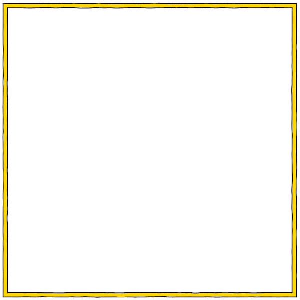
Pretty good. Note that there are places in which the black lines and the golden line are not quite aligned due to fluctuations. If I want to get rid of these spots, then you can simply reduce the amount of oscillation.
Implementing a vertical space primitive is quite simple; it just performs an offset increment. Let's add a little space:
L(3, black) L(10, gold) L(3, black)

VS(5)

L(3, black) L(10, red) L(3, black)
When drawing lines, angles can be realized by drawing between the offset and the drawing along the map clockwise. But in general, I need to implement truncation on each side of the map border to create an angular connection with a bevel . This will be necessary to create borders with patterns that are correctly joined at the corners, and in the general case will eliminate the need to draw elements with edges at an angle that would otherwise be required. (*)
(Note: as will be said in the following sections, over time I refused to use truncation regions when realizing angles. The main reason is that to create complex angles, for example, square offsets:
increasingly complex truncation areas are required. Also, over time, I found a better way to work with patterns in corners. Instead of returning and rewriting this part of the article, I decided to leave it to illustrate the process of “creativity.”)
The main idea is to truncate each border diagonally and create four truncated areas in which each side of the border will be drawn:
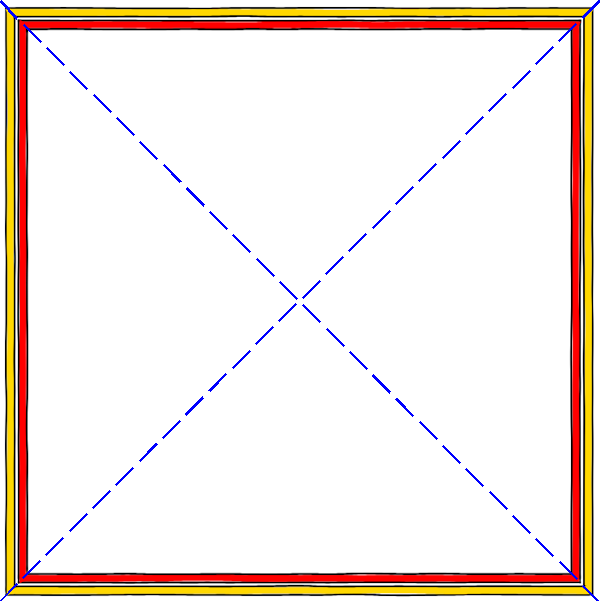
When truncating, everything drawn in the corresponding area will be cut off at the desired angle.

Unfortunately, this creates small gaps along the diagonal lines, probably because the browser imperfectly performs smoothing along the truncated edge. The test showed that a background shines through the gap between the two edges. It was possible to fix this by expanding one of the masks a bit (half the pixel seems to be enough), but this sometimes does not solve the problem.
Next you need to implement geometric shapes. Unlike lines, they are repeated in the pattern, filling the side of the border of the map:
A person would draw this pattern from left to right, drawing a rectangle, a rhombus, and then repeating the same until the entire border is filled. Therefore, this can also be implemented in the program by drawing a pattern along the border. However, it will be easier to first draw all the rectangles, and then all the rhombuses. It will be enough just to draw along the border the same geometric figure at intervals. And it’s very convenient that each element has the same interval. Of course, a person would not do that, because it is too difficult to arrange the elements in the right places, but this is not a problem for the program.
That is, the procedure for drawing simple geometric shapes needs parameters in which all the dimensions and colors of the figure are transferred (i.e. width, length, line thickness, line color and fill), as well as the starting position (which for reasons that will become clear soon, I will consider the center of the figure), the horizontal space interval for the transition between repetitions, and the number of repetitions. It will also be convenient to indicate the direction of repetition in the form of the vector [dx, dy], so that we can perform repetitions from left to right, from right to left, up or down, simply changing the vector and the starting point. Put it all together and get a strip of repeating shapes:

Using this code several times and rendering with the same offset, I can combine the black and white stripes to create the map scale:

Before I begin to figure out how to apply all this to the real border of the map, let's first implement the same functionality for ellipses and rhombs.
Rhombuses are just rectangles with rotated vertices, so you only need to make a small change to the code. It turned out that I still do not have ready-made code for rendering the ellipse, but it is very easy to take the parametric view of the ellipse and create a function giving me the points of the ellipse:

Here is an example (created manually) that uses the features implemented above:

For such a small amount of code, it looks pretty good!
Let's now solve the complex case of borders with repeating elements: corners.
If there is a border with repeating elements, there are several ways to solve the problem with corners. The first is to adjust the repetitions so that they are executed in the corners without noticeable marriage:
Another option is to stop the repetition somewhere near the corner on both sides. This is often done if the pattern cannot be easily “rotated” in the corner:
The last option is to close the pattern with some corner decoration:
Someday I will get to the corner decorations, but for now we will use the first option. How to make a pattern of stripes or circles “rotate” in the corners of the map without gaps?
The main idea is to place the pattern element exactly in the corner so that one half of it is on one edge of the map and the other is on the adjacent one. In this example, the circle is exactly in the corner and can be drawn from any direction:
In other cases, the element is half drawn in one direction, and half in the other, but the edges coincide:
In this case, a white stripe is drawn on both sides, but is connected in the corner without gaps.
There are two aspects to consider when placing an element in a corner.
First, the corner element will be split and mirrored relative to the diagonal passing through the center of the element. Elements with radial symmetry, for example, squares, circles and stars, will not change their shape. Elements without radial symmetry, for example, rectangles and rhombuses, will change shape when mirroring relative to the diagonal.
Secondly, for the corner elements of the two sides to connect correctly, there must be an integer number of elements (*) along both sides of the map. They do not have to be the same number, but there must be an integer number of elements on both sides. If a fractional number of patterns is contained on one side, then from one edge the pattern will not coincide with the adjacent side.
(* In some cases, for example, with long stripes, partial repetition may occur with full repetition and the elements will still be aligned. However, the resulting corner element will be asymmetric and differ in length from the same element on the sides of the map. An example of this can be seen here:

A white bar of scale occurs with different partial repeats and as a result an element shifted relative to the center is obtained. For map scale, this is not always the case, because it shows the absolute distance and does not have to be symmetrical. But for a decorative pattern this usually looks bad.)
Here is an example showing how an integer number of repetitions is trimmed exactly in the corner:

If you do the same from all four sides, then the corners will coincide and the pattern will be seamlessly located along the entire length of the border:
Upon careful examination, you will notice that the pattern does not occur exactly in the corners. Half of the circle in each corner is taken from each side, and these two halves are independently drawn by hand, therefore they are not perfect. But now they are close enough to this.
So, we can realize a perfect connection of the pattern in the corners, choosing an integer number of repetitions for each edge. However, the solution to this problem is nontrivial.
First, suppose we know that the side is 866 pixels long, and we want to repeat the element 43 times. Then the element should be repeated every 20.14 pixels. How do we set the specific length of an element (and in the general case, a pattern of elements)? In the example above, I added extra space between the circles. But if the circles initially touched each other, then this will change the pattern. Perhaps it is worth stretching the circles so that they continue to touch each other?

Now the elements are touching, but the circles have turned into ellipses and the corners have a strange shape. (Remember, I said that elements without radial symmetry change shape when reflected relative to an angle? For stripes, this will not be a big problem.) Or, perhaps, it is worth compressing all the elements so that they touch each other and fit in a suitable length:

But in order to realize this, we need to make the elements much smaller than they were originally. None of these options seem perfect.
The second problem occurs when the sides of the card are of different sizes. Now we need to solve the problem of finding an integer number of repetitions suitable for both sides. It would be ideal to find one solution that fits both sides. But I do not want to do this at the cost of too much pattern change. It might be better to create slightly different patterns on both sides if they are both close enough to the original pattern.
And finally, the third problem arises when I use the function of superimposing several elements on each other:

I do not want to make any changes to the pattern that will destroy the relationship between the elements. I think that with proper scaling, the ratios as a whole will remain, but I need to test this.
Interesting task, right? So far I have no particularly high-quality solutions for her. Perhaps they will appear later!
Part 4
So, we have implemented primitives for drawing lines and geometric shapes. I started working on using repeating shapes to fill the borders and talked about the difficulties of placing arbitrary patterns on the border of the map so that they fit perfectly in the corners. The main problem is that in the general case, you have to make the pattern longer (or shorter) so that it fits sideways. Options for changing the length of the pattern — adding or removing spaces, changing the length of the elements of the patterns — lead to various changes in the pattern itself. It seems that the task of selecting a pattern from several elements is very difficult!
When I come across such seemingly uncompromising tasks, I like to start by implementing a simple version. Unsuccessful tasks can often be solved by repeatedly solving "simple" problems until the result is good enough. And sometimes the implementation of a simple version gives some understanding that simplifies the solution of a more complex problem. If it doesn’t get better and the problem remains uncomfortable, then at least we will have a simplified version that can still come in handy, albeit not quite as it should.
The easiest way is to change the length of the pattern by adding lengths without changing anything in the pattern. Essentially, this adds blank space to the end of the pattern. (Note: it is better to distribute the empty space between all the elements in the pattern.) It is worth considering that such a solution can only lengthen the pattern. We can always add empty space to the pattern, but cannot take it if necessary - perhaps there will be no more empty space in the pattern!
With this approach, the pattern location algorithm on the side of the card will be very simple:
- Divide the length of the side of the card by the length of the pattern and round it down to determine the number of repetitions of the pattern that fit on that side.
- The distance between the elements in this case will be equal to the length of the side divided by the number of repetitions. (This is the closest to the original location, given that we can only add space.)
- Draw a pattern along the side, taking into account the calculated distance.
It was difficult to implement this system. The corners stubbornly did not want to coincide. It took me too much time to realize that when the map is not square, I cannot draw truncation areas for four sides from the center of the map, because this creates truncation angles that are not equal to 45 degrees. In fact, truncation areas should resemble the back of an envelope:

When I figured this out, the algorithm began to work without problems.
(But do not forget the previous note that over time I abandoned truncation areas!)
Here is an example with a ratio of approximately 2: 1:

On this scale, it’s pretty hard to notice, but the corners connect correctly and there is only a slight visual difference between the sides. In this case, the algorithm for aligning the patterns only needs to insert fractional pixels, so it is invisible to the eye, especially because the contours of the circles are overlapped by a pixel.
Here is another example with stripes:

This is the top of the square border. Here is the same border on a more rectangular map:

Here you can see that on the side of the card there is a visually larger gap between the bands. The algorithm should insert no more space than the length of one full element; therefore, the worst case occurs when we have long elements and a short side that is slightly different from a suitable size. But in most practical cases, alignment is not very harmful.
Here is an example with a pattern of several elements:

Here the stripes overlap the stripes:
You can see that since the same alignment is performed for each element, the stripes remain centered relative to each other.
I suggested that a good solution for placing the pattern on the side of the map would be difficult, but a very simple approach with evenly distributing the pattern element to fill the desired space works quite well for many patterns. This is a reminder to all of us: there is no need to assume that the decision must be complicated; it may be easier than you think!
However, this solution does not work for patterns with touching elements, for example, for map scale. In this case, adding space shifts the elements:
Another option for lengthening a pattern, which I mentioned above, is stretching the individual elements of the pattern. It is suitable for something like a scale pattern, but it will look bad in a pattern with symmetrical elements, because stretching will make them asymmetric.
The implementation of the stretch option turned out to be more complicated than I expected, mainly because I had to stretch the elements at different edges of the map by different sizes (because the map may not be square but rectangular), and also dynamically change the location of the elements based on the new stretched ones sizes. But after a few hours I managed to achieve this:
Now I have all the features necessary to draw the border of the map (although the border elements themselves are created manually):

I converted the image to grayscale, because I did not want to bother with the selection of colors, and the card itself is rather boring, but as a proof of concept the borders look pretty pretty.
Part 5
In part 2, I developed the Map Border Description Language (MBDL) grammar, and in parts 3 and 4, I implemented procedures to execute all the language primitives. Now I’ll work on connecting these parts so that I can describe the border on MBDL and draw it on the map.
In Part 3, I wrote the MBDL grammar so that it works with the Nearley Javascript Parsing Tool . The finished grammar looks like this:
@builtin "number.ne"
@builtin "string.ne"
border -> (element WS):+

WS -> [\s]:*

number -> WS decimal WS

color -> WS dqstring WS

element -> "L(" number "," color ")"
element -> "VS(" number ")"
element -> "(" WS (element WS):+ ")"
element -> "[" WS (geometric WS):+ "]"
geometric -> "B(" number "," number "," color "," number "," color ")"
geometric -> "E(" number "," number "," color "," number "," color ")"
geometric -> "D(" number "," number "," color "," number "," color ")"
geometric -> "HS(" number ")"
By default, when successfully parsing a rule using Nearley, the rule returns an array containing all the elements that correspond to the right side of the rule. For example, if the rule
test -> "A" | "B" | "C" matched with string
Athen Nearley will return
[ "A" ] An array with a single value is the string “A” corresponding to the right side of the rule.
What does Nearley return when an element is parsed using this rule?
number -> WS decimal WSThere are three parts to the right side of the rule, so it will return an array with three values. The first value will be the one that returns the rule for WS, the second value will be the one that will return the rule for decimal, and the third value will be the one that will return the rule for WS. If, using the above rule, I will pars "57", then the result will be as follows:
[

 [ " " ],

 [ "5", "7" ],

 [ ]

]
The final result of Nearley parsing will be a nested array of arrays, which is a syntax tree . In some cases, the syntax tree is a very useful representation; in other cases, not quite. In Dragons Abound , for example, such a tree is not particularly useful.
Fortunately, Nearley rules can override standard behavior and return whatever they want. In fact, the (built-in) rule for decimal does not return a list of numbers, it returns the equivalent Javascript number, which in most cases is much more useful, that is, the return value of the number rule has the form:
[

 [ " " ],

 57,

 [ ]

]
Nearley rules redefine standard behavior by adding a post-processor to the rule, taking a standard array and replacing it with what you need. A postprocessor is just Javascript code inside special brackets at the end of a rule. For example, in the number rule, I’m never interested in possible spaces on either side of the number. Therefore, it would be convenient if the rule simply returned a number, and not an array of three elements. Here is a post-processor that performs this task:
number -> WS decimal WS {% default => default[1] %}This post-processor takes the standard result (the three-element array shown above) and replaces it with the second element of the array, which is the Javascript number from the decimal rule . So now the number rule returns the real number.
This functionality can be used to process an incoming language into an intermediate language, which is easier to work with. For example, I can use Nearley grammar to turn an MBDL string into an array of Javascript structures, each of which represents a primitive identified by an “op” field. The rule for the line primitive will look something like this:
element -> "L(" number "," color ")" {% data=> {op: "L", width: data[1], color: data[3]} %}That is, the result of parsing “L (13, black)” will be the Javascript structure:
{op: "L", width: 13, color: "black"}After adding the appropriate post-processing, the result returned from the grammar can be a sequence (array) of operation structures for the incoming line. That is, the result of parsing the string
L( 415, “black")

VS(5)

[B(1, 2, “black", 3, “white") HS(5) E(1, 2, “black", 3, “white")]
will be
[

 {op: "L", width: 415, color: "black"},

 {op: "VS", width: 5},

 {op: "P",

 elements: [{op: "B", width: 1, length: 2,

 olColor: "black", olWidth: 3,

 fill: "white"},

 {op: "HS", width: 5},

 {op: "E", width: 1, length: 2,

 olColor: "black", olWidth: 3,

 fill: "white"}]}

]
which is much easier to process to create a map border.
At this point, you may have a question - if the post-processing stage of the Nearley rule can contain any Javascript, then why not skip the intermediate view and simply draw the border of the map right during post-processing? For many tasks, this approach would be ideal. I decided not to use it for several reasons.
Firstly, in MBDL there are a couple (*) of components that cannot be executed during the parsing process. For example, we cannot draw repeating geometric elements (strip or rhombus) during the parsing process, because we need to know information from other elements in the same pattern. In particular, we need to know the total length of the pattern in order to understand how far we need to arrange the repetitions of each individual element. That is, the element of the pattern should still create an intermediate representation of all geometric elements.
(* There are other components with similar limitations that I haven’t talked about yet.)
Secondly, Javascript in Nearley is embedded in the rules, so we won’t be able to pass additional information to Javascript, except for global variables. For example, to draw the border, I need to know the size of the map, the four truncation areas used, etc. Although I can add code that makes this information available to Nearley post-processors, it will be a little messy and it might be difficult to maintain such code.
For these reasons, I am parsing into an intermediate representation, which is then executed to create the border of the map itself.
The next step is to develop an interpreter that receives an intermediate representation of MBDL and runs it to generate map boundaries. This is not very difficult to do. Basically, the job is to set the initial conditions (for example, generate truncation regions for the four sides of the map) and iterate over the sequence of structures of the intermediate representation with each one.
There are a couple of slippery moments.
First, I need to go from rendering from inside to drawing from inside to outside. The reason is because I want most of the borders not overlapping the map, so I need to draw the borders so that the lines of the inner edge coincide with the edges of the map. If I draw from the outside inward, then I need to know the width of the border before I start drawing so that the border does not overlap the map. If I draw from the inside out, I just start from the edge of the map and draw out. It also allows you to optionally impose a border on the map; just start the border with a negative vertical space (VS).
Another difficult point is the repeating patterns. To draw repeating patterns, I need to look at all the elements of the pattern and determine the widest one, because it will set the width of the whole pattern. I also need to look at and track the length of the pattern so that I know how much distance to leave before each repetition.
Here is an example of a rather complex border that I used to test the interpreter:

I think it was possible (necessary?) To attach it for testing to the parser, but for this border I just created an intermediate view manually:
[

 {op:'P', elements: [

 {op:'B', width: 10, length: 37, lineWidth: 2, color: 'black', fill: 'white'},

 {op:'B', width: 10, length: 37, lineWidth: 2, color: 'black', fill: 'black'},

 ]},

 {op:'VS', width: 2},

 {op:'L', width:3, color: 'black'},

 {op:'PUSH'},

 {op:'L', width:10, color: 'rgb(222,183,64)'},

 {op:'POP'},

 {op:'PUSH'},

 {op:'P', elements: [

 {op:'E', width: 5, length: 5, lineWidth: 1, color: 'black', fill: 'red'},

 {op:'HS', length: 10},

 ]},

 {op:'L', width:3, color: 'black'},

 {op:'POP'},

 {op:'VS', width: 2},

 {op:'P', elements: [

 {op:'E', width: 2, length: 2, lineWidth: 0, color: 'black', fill: 'white'},

 {op:'HS', length: 13},

 ]},

]
I created this view through trial and error. Be that as it may, the interpreter works!
As a last step, let me use the parser to create an intermediate view from the MBDL version. There is nothing much to show me here: I had to fix a few field names, but otherwise the code worked well. For the border, I used a slightly different version of MBDL:
[B(5,37,"black",2,"white") B(5,37,"black",2,"black")]

VS(3)

L(3,"black")

{L(10,"rgb(222,183,64)")}

[E(5,5,"black",1,"red") HS(-5) E(2,2,"none",0,"white") HS(10)]

L(3,"black")
She draws the same border, but in a slightly different way. I also changed the syntax for the overlay, replacing the parentheses with curly braces so that it is more different from the other syntax.
To show why I wanted to draw from the inside out, and not just automatically place the border on the outside of the map, I can add a negative vertical space to the beginning of this border to move the map scale inside the map edge:
Now I have most of the infrastructure necessary for the procedural generation of map borders: a boundary description language, a language parser, and procedures for performing an intermediate representation. It remains only to deal with the difficult part - the procedural generation!
Part 6
Now that the entire MBDL has been implemented, I intended to proceed to the procedural generation of map borders, but I’m not sure yet how I want to do this, because I will linger a bit and implement a couple more MBDL features.
In the first discussion of corner processing with patterns, I talked about a couple of different approaches. In the end, I realized the beveled corners, but there was a second option: stop the pattern near the corner, as in these examples:


Such a solution is often used when the border pattern is some kind of asymmetric figure, runes, or something else that cannot be rotated 90 degrees, while maintaining alignment. But it’s obvious that this will work with geometric shapes.
This may be the option that you choose before generating the border, but you can add a bit of flexibility if you enable it from one part of the border and use the beveled corner on the other. To do this, I have to add a new command to MBDL. I suspect that other options may arise for different parts of the border, so I will add a general options command:
element -> "O(MITER)"
element -> "O(STOPPED)"
element -> "O(STOPPED," number ")"
(Here again, for clarity, we omit spaces and some other details.) So far, the only options are “MITER” for beveled corners and “STOPPED” for stopping near corners. If no value is transmitted STOPPED, then the program stops the pattern at some reasonable distance from the corner. If the value is transmitted, the pattern stops at that distance from the corner.
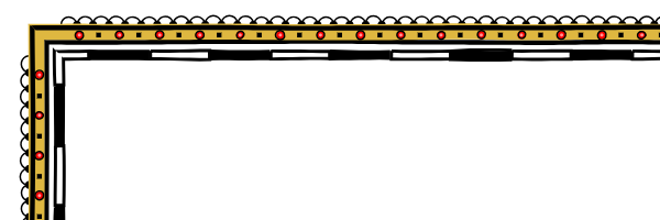
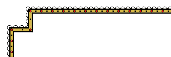
If STOPPED corners are used, then I stop drawing the corner pattern away from the corners. Here's what it looks like:

Here, I used the MITER option for the black and white scale pattern, so it mirrors with respect to the angle. For a pattern of red circles and black squares inside a gold line (and for a pattern of circles outside the border), I used STOPPED. You can see that these two patterns end near the corner.
However, there are a couple of problems. Firstly, we see that on the left the closest element to the corner is a black square, and on top is a red circle. It happened because the corner is near the start of the repeat on one side and near the end of the repeat on the other. But it looks weird. It would be better if the corners were symmetrical, even if for this we had to add another element to the end of the pattern. Secondly, you can see that the pattern outside the border (semicircles and black dots) also ends in one repeat to the corner. But since the length of this repeat is much less than the length of the red circles / black squares, they end up in different places. It would probably be better if all the patterns stopped at the same distance from the corner.
To fix the first problem, you need to add another repetition of the first element of the pattern at the end of each side of the border. But actually it’s a bit more complicated, because I could use a negative horizontal offset inside the pattern to overlap several elements (as done here). You also need to add another repeat to any element of the pattern that has the same starting point as the first element.

Now the pattern is symmetrical with respect to the angle and looks much better.
Next, I need to track the longest STOPPED pattern and stop each STOPPED pattern at this distance:
Now the pattern of white circles is set aside more, but it is still not aligned with the pattern of red circles. Why? It happened because the white circle pattern is farther away from the edge of the map, and the length of the border is longer than where the red circle pattern is drawn. To fix this problem, you need to move the patterns also and considering their offset relative to the edge of the map.

Now everything is beautifully aligned.
The second option for angles is the square offsets in the corners, for example these:
It will be much more difficult to implement this!
However, the grammar of this option is simple and uses the Option opcode:
element -> "O(SQOFFSET)"
element -> "O(SQOFFSET," number ")"
The number indicates the size of the square displacement for the element on the edge of the map; Elements with different offsets must be aligned accordingly. If there is no number, the program selects the appropriate offset size. Zeroing the number disables the square offset. This allows you to create borders in which some elements use square offsets, while others do not, as in this border:
The first thing I realized was that I would need additional truncation areas because I use truncation to process places where the border changes direction. SQOFFSET will require more complex truncation areas; You will also need separate areas for different items when you enable and disable SQOFFSET. Given that truncation areas add unwanted artifacts anyway, this seems like too much work.
When I worked on stopable patterns above, I implemented filling in an asymmetric pattern to add another repeat from one end of the pattern. I also realized that this would eliminate the need for beveled corners. I will simply draw all the patterns along the border clockwise, starting the pattern in one corner and ending near the next corner. This will allow me to get rid of truncation areas.
The most important thing in this new way of working with corners was that the first element of the pattern is no longer “divided” into two sides. If you look at the black and white scale patterns on the maps above, you can see that there is a white rectangle passing through the corner. Now the white rectangle will abut the corner:

Maps are drawn in both ways, but this is not a very big problem.
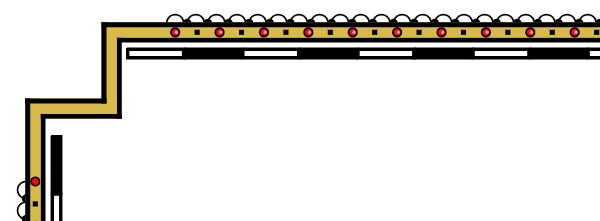
For starters, I implemented offsets for lines. To do this, it was enough to turn the line relative to the corresponding angles:

As you can understand, I can combine angles with offsets and regular angles, as in the map above:

Of course, turning the patterns around the corner is more difficult. The general idea is to draw from one corner to almost the other, and so on along the border, until we get back to the beginning. It is theoretically enough to draw only horizontal and vertical patterns, and everything should be beautifully aligned; actually tracking all of this is pretty dreary. In fact, I had to completely rewrite the code twice and write a bunch of paper, but I won’t talk about this in detail. Just show the result:

An annoying optical illusion arises in the corners - the corner element seems uncentered closer to the outside of the corner. In fact, this is not true, but it seems so, because closer to the inside of the corner there is visually more empty space.
Since the segments of the offset angles are quite short, it is very easy to create a nonequilibrium pattern in the corner:
Sometimes it looks pretty ugly. It reminded me of an old joke:
Patient: “Doctor, when I do this, it hurts me.”
Doctor: “Then don't do that!”
Therefore, I will try not to do so.
Usually I will not draw the map scale along the offset angle, but if I need it, I will need to use the option that stretches the pattern so that the map scale fits into the corner without gaps between the rectangles:

You can see that as a result, the size of the scale rectangles varies markedly. That is, this is not a very good option. (By the way, the offset angles also have a bug in the pattern of circles. Later I fixed it, but as I said, it is very difficult to do it.)
If the pattern is too large to fit on the segment of the offset angle, then the algorithm simply surrenders:

Which is far from ideal, but, as I said above, "Then do not do it." (It’s actually not very difficult to add a compression or stretch function if I needed it.)
What happens if I use both offset corners and the option that stops the patterns in front of the corners? In this case, I just stop not far from the offset corners:
It seems to me that this is a logical decision.