Cars "catamarans"

“Simplicity is the most difficult thing in the world; this is the extreme limit of experience and the last effort of a genius. ”Leonardo da VinciNow often looking at the competition of solar vehicles in Australia, you can see the identity of some cars, the shape of which resembles a catamaran. What is the reason for this? What are the benefits of this form not only for solar machines?
About this, and much more will be this article.
First, a little theory.
The aerodynamic drag of a car can be reduced to three parameters.
- Resistance of the frontal area of the car.
- Form resistance (air friction on the side surfaces of the car).
- A turbulence of air near the wheels and under the body.
In this case, only the 1st parameter will be considered. Since the limit on the second one is a drop, it was already partially considered in previous articles on “tails on a car” and the future amphibiousness of electric vehicles , the third mainly depends on the width of the tire and the shape of the disk, and does not significantly affect the final result (compared to the first two).
By frontal we mean the area F of the largest vertical cross section of the ATS, i.e. contour of its frontal projection. In approximate calculations, the real contour is simplified by segments of straight lines, allowing you to represent the area as a set of simple geometric shapes that do not require complex calculations.
In the case of a car with dependent suspension, the frontal area is approximately equal to the sum of 3 elementary areas, m2:
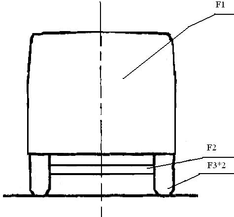
Where
- cabin area by wings, m2;
- beam area of the front axle, m2;
- the open area of the front wheels, m2.
Independent suspension vehicles do not have a protruding beam under the car, and therefore the calculation becomes easier. The shape of the body depends on the size of the frontal area, and the smaller this area, the better you can “bring” the correct body shape in length to reduce Cx (shape resistance).
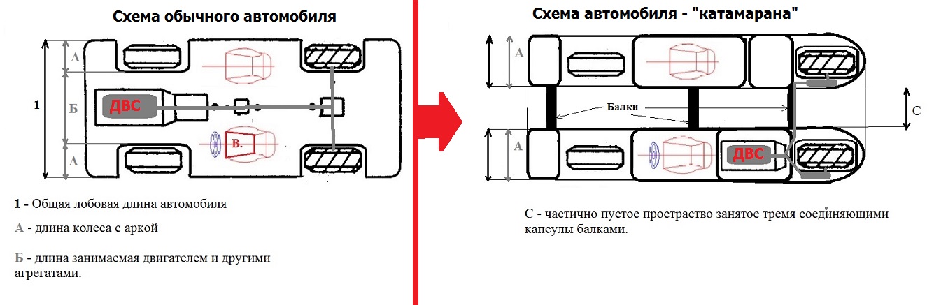
Due to the space “C”, vehicles with a catamaran layout can reduce the total frontal area of the car.
Chasing the sun and aerodynamics.
The principle of saving frontal area due to the catamaran design in recent years is clearly visible on the example of single- seat WSC.
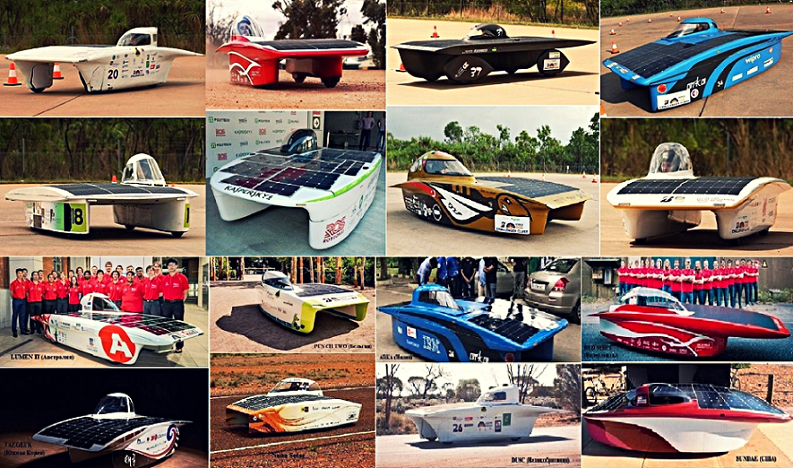
These solar cars, like many others not shown in the picture, use the same principle of organization of form, resembling a catamaran. The need for this form is the desire to save energy at high speed.
Speed records due to streamlining, however, were characteristic of this body shape before.
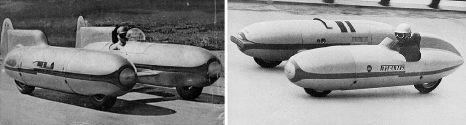
So in 1949 the racer Piero Taruffy built two catamaran cars at once - Tarf I, Tarf II. Outwardly, they were practically no different.
In 1949, Taruffy received a patent for his double-hull record car in the United States. From 1951-1952, the car was built by Gilera using its most powerful motorcycle engine. He gave out 65 hp. at 10400 rpm
The engine was located in the right nacelle, the pilot and control system in the left. On October 14, 1954, Taruffy set a world record for cars in the class up to 500 cm3 - 201 km / h.
But it was only Tarf I. At the same time, with only a slight lag, Taruffy was building a second car of a similar design - Tarf II. On it stood a powerful 1720 cc 290-horsepower Maserati engine. Due to the very small cockpit, there was no room for the steering wheel in the car, and the control was carried out by two levers, on the right and left, located at the pilot's hands down. The car had a layout opposite to the first generation - the driver was sitting on the right, the motor was on the left.
Amazingly, the Tarf II, which began to be built later than the Tarf I, finished earlier. The first record - the average speed at a distance of 50 miles, 231.744 km / h - Taruffy set it on January 15, 1952.
From single to 2-4 local land catamarans.

The 1967 car dealership was rich in surprises, and one of them was the strange OSI Silver Fox concept.
At first glance, its design was irrational - because the body clearly needed rigidity in the central part, so that it would not sag under the influence of external forces. Also, the passenger and driver sat at a great distance from each other.
Nevertheless, the Silver Fox two-pont circuit had one big advantage - it allowed to pass under the car exactly the amount of air that was required on a particular track for steady movement. Simply put, the body allows you to adjust the level of downforce. So that the volume of air masses that could be passed could be regulated, Silver Fox had three jumpers-wings: the rear “spoiler” was stationary, the central one was adaptive, changing the angle of attack depending on the moment of inertia, and the front one was mechanically adjustable, like most modern stationary wings .
As a result, the concept, equipped with a 1-liter 4-cylinder Alpine engine and having a curb weight of 500 kilograms, could accelerate to 250 kilometers per hour! At the same time, fuel consumption was not excessive, which was also important for participating in daily marathons for which the car was being prepared.
Other interesting features of OSI Silver Fox include the original “Leman” steering wheel arrangement (on the right side) and a kind of balancing between the sides - the engine located in the left pontoon was balanced by the driver and the spare wheel, which were on the right.
The shape of the car, reminiscent of the letter “P” in profile, has not been forgotten in our time. The PrISUm research lab, consisting of students from Iowa State University, has built a prototype Penumbra P14 solar electric car that can be used on regular roads.

This car still has the potential to reduce drag if the developers apply the idea of "humps" from the Dodge Viper on the roof.
Structurally, the body is very simple, glazing and wheels are the most common, even there is a radio tape recorder like a regular car. The only obvious difference is the solar panels on the roof and hood. As conceived by the authors of the project, this car should be a certain transitional stage between a specialized solar car and an ordinary electric car for family use. Among the sponsors of the project are Siemens and Boeing, which can be considered not at all superfluous, since the cost of development and construction is estimated at no less than $ 750,000. Penumbra has a range of 322 km. The body of this car is made of composite materials based on carbon fibers, like most solar electric cars, which allows us to count on a good ratio of strength to weight.
In addition to Penumbra, there are 2 more models of solntsekars having a similar shape.

Stella Lux
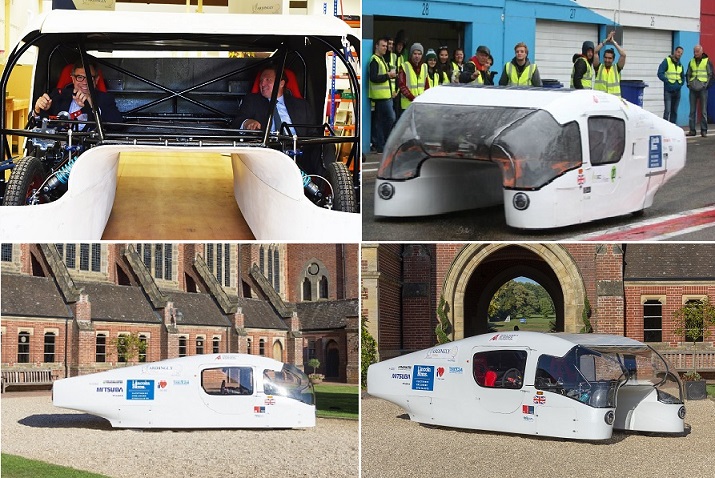
Ardingly Solar Car
These electric cars are less suited to normal user use, but have better performance.
Sometimes minus to minus gives a plus ...
The Danish company RUF International is actively developing a project combining private and public transport. The project website presents various options for the concept of a new monorail.
According to the project, small sections of the track can be overcome on ordinary roads, but basically more economical movement on the rails of the original design is planned.
Such a hybrid vehicle is planned to be made fully automatic, but if necessary, the driver can still control the machine independently. True, the speed of movement on rails will have a limit of no more than 120 km / h, which cannot be disabled.
According to the RUF International project, the network of roads for such cars will consist of 25-kilometer rail sections with special “crossings” every five kilometers so that some drivers can join the movement, while others turn off or move off the rails. The maximum speed between “crossings” (150 km / h) when approaching the interchanges will automatically be reduced to 30 km / h.
It is planned that U-shaped electric cars will receive energy when driving on a monorail in a wireless way, and this should be enough for a short movement on ordinary roads. Due to this hybridization, it will be possible to reduce the weight and dimensions of electric vehicle batteries, which will positively affect the other characteristics of this automated personal transport.
Two options for using such electric vehicles are being considered.
- Personal electric car with autopilot level 5.
- "Car sharing" based on the user's personal card.
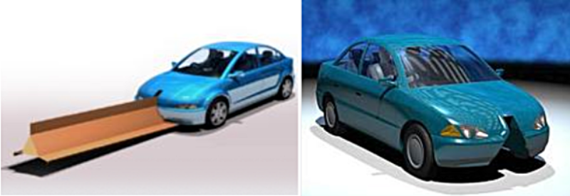
The RAF system is designed with a high level of versatility and therefore it is planned that it will be able to use machines of different classes. Trucks, Buses and cars in this case simply need to be adapted for movement on rails due to the V-shaped channel passing along the underbody of the car.
"Slot" runs in the middle and inside divides the interior into two parts. The developers suggest using the "hill" as an armrest or "place for the child."
The monorail system is designed for large cities, but the authors of the project did not forget about the residents of the suburban area: a hybrid transport with electric and fuel engines is provided.
The main advantage from the introduction of the RUF hybrid transport system will be its environmental component, which will be expressed in the reduction of energy costs for transportation and maintenance of roads.
For example, public commuter transport called Maxi-RUF is a bus that can carry ten passengers, not counting the driver.
The company has been working on its concept since 1988. RUF International has 16 sponsors, including the Danish subsidiary of Siemens and the Danish ministries of energy and the environment.
At first glance, the concept of the Danes is in doubt, although this project has actually very ancient roots. So back in the 19th century, French engineer Charles Larting developed a rail similar in appearance for locomotive movement.
This rail transport received the name - Monorail of the Lartig system.
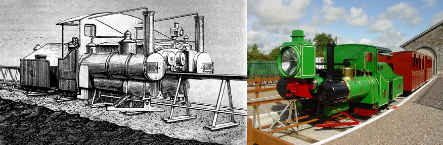
This is one of the first monorails in general, and at the same time one of the first monorails, which had practical application. One of the most famous roads on which it was used was called Listowel and Ballybunion Railway.
In cross section, the path was similar to the letter “A” about a meter high. Above was the main (bearing) rail, from the bottom on the sides there were two guide rails. This path was established on the surface of the earth on sleepers. Sections in the form of the letter “A” were installed at a distance of about a meter from each other. Since the length of the “legs” of the sections can be arbitrary, during construction there is no need to level the ground under the tracks!
In addition to the main wheels resting on the upper rail, the locomotives and wagons had supporting wheels that rested on the guide rails and protected the train from tipping over. The Laring system is highly adaptable, easy to disassemble and carry from place to place.
The most important factor in the operation of such a road is to ensure the balance of the train. Before departure, the conductor made sure that the number of passengers in half of the car on one side of the rail corresponded to the number of passengers in half of the car on the other side of the rail. In this case, the RUF project will not bypass this “obstacle” during implementation, but cars and buses by weight certainly cannot be compared to trains.
Amphibious "catamarans"
Is a catamaran originally a water vehicle? So really there were no amphibious hybrids of this design?
Were! And especially the original home-made can be found in the period of the USSR.
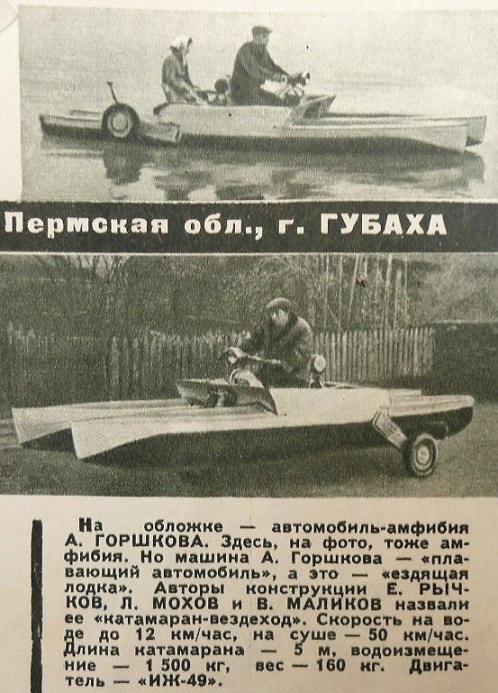

Universal catamaran of the USSR on water - ice - earth. A note about him was in the journal Tech-Youth 1962, issue number 4, and in full looks like this.
“What to do for lovers of water sports and long-distance tourism, living away from rivers and ponds? Where to store motor boats and boats, how to deliver them to the water, where to put the wheelsets and other vehicles necessary for transportation and unnecessary when the journey begins on the water?
Reflecting on these issues, I was convinced that the best solution is an amphibious all-terrain vehicle that can move on the ground on wheels, swim on water, and in winter glide on skis in the snow. On such an all-terrain vehicle, it costs nothing to drive several tens of kilometers along the road. Having reached the reservoir, it is enough to remove the wheels and continue the journey through the water.
To give amphibian as much stability as possible, I decided to make it in the form of a catamaran. To do this, it was necessary to make two identical streamlined shells. I installed 12 frames of 10 mm plywood on the stock, embedded 12 external stringers from a pine lath measuring 8x18 mm and 6 internal ones into them. After this, the frame of each shell was pasted over with one layer of birch veneer.
Then, a composition for gluing the frames with coarse calico and fiberglass is prepared from epoxy resins: (EDF-1 - 60 parts, EDF-3 - 40 parts; dibutyl phthalate - 13 - 15 parts, poly-ethylene polyol - 16-18 parts). To avoid getting the composition on your hands, face, rubber gloves and a dumb overalls with cords on the cuffs are needed. Epoxy resins are poured into a tinplate bathtub and heated to 80–90 ° С.
After that, the bath is installed on the scales and a plasticizer (dibutyl phthalate) is added to it. The mixture is thoroughly mixed and simultaneously cooled to 24 ° C. Now in the cooled mixture you need to add a hardener (polyethylene polyol), mixing it strongly to avoid clumping. All this is applied uniformly on the surface of the shell, and the temperature should be about 24-30 ° C, because otherwise the mixture quickly thickens and poorly penetrates the weaving of the fabric. Coarse calico or fiberglass is stretched onto the coating layer and carefully rolled with spatulas. On a birch veneer, a sticker is made of one layer of fiberglass and one layer of calico. Only in the places of future openings for connecting frames are additional transverse belts of 4 layers of fiberglass glued, each 20 cm wide.
After the irregularities are smoothed and smoothed out, each shell is glued entirely with one layer of fiberglass, and an additional strip is glued on the bottom.
Then, two streamlined shells are interconnected by four welded detachable frames from thin-walled chrome-power pipes. Removable forks are hung on the protruding ends of the two front frames, to which either the wheels from the Tula-200 scooter, or hydrofoils, or skis are attached.
Two front wheels are connected ball-nirno and are rotary. The third wheel, mounted between the two rear frames on a trapezoidal truss, is the drive wheel. It is planned to install a motor with a propeller for movement on water or snow.
At present, the brackets of the front wheels and the truss of the rear wheel are removed for water movement. A bracket with a mobile carriage for installing the Moscow steering motor is mounted in place of the farm.
In the summer of 1961, pilot tests of the catamaran on water began. With the engine "Moscow" in 10 liters. with. and with 4 passengers the catamaran freely walked around dural boats of the Mir type with the same engine and 2-3 passengers. At full throttle, the catamaran entered the planing mode, two trickles of whiskers appeared in front, and between the “tails” of the shells, two small fan-shaped, diverging plumes of water. Whirlpools characteristic of flat stern motor boats were not observed.
The catamaran proved to be very stable due to a kind of “self-regulation” due to the pressure of a diverging stream of water on the tail parts of the shells. Draft with a load of 800 kg was only 120 mm. The weight of the catamaran with the Moscow motor is approximately 120 kg. Control of the rotation of the motor "Moscow" made in the rear left cab. Gas is regulated by turning the flexible hose.
During testing, rigidity and sufficient mechanical strength of the shells were revealed. It can be assumed that in terms of stability and speed the catamaran will not yield to the existing types of motor boats. If necessary, the catamaran shell can be disconnected for transportation by road or rail.
In the future, tests will be conducted with hydrofoils, skis, a 30-horsepower M-61 engine and hydraulic rear wheel drive.
When building the catamaran, I used the experienced epoxy resins of the Nizhne-Tagilsky plastic plant. Despite the imperfection of the manual manufacture of shells, they well proved themselves in mechanical strength and water resistance. Although these resins are dark in color, they can be painted as needed. During the construction of the catamaran, the Ural Forestry Institute gave me some help, and members of the Sverdlovsk Marine Club DOSAAF helped in the tests.
B. DEAR, engineer.
It is a pity the author did not think about the airborne version of the use of his "all-terrain vehicle-catamaran," but we have thought about an air-catamaran already in our time.
Flying Catamarans
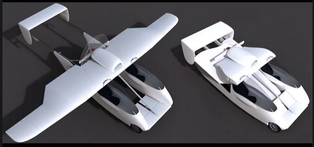
Carplane GmbH has created a specific flying car.
This flying car has not one, but two whole fuselages, and has the ability to transform from car to plane. How does this happen? When the Carplane moves on the ground, the wings and propeller are folded in the middle of the car, just between two single-seat fuselages. If a flying machine needs to take off, then these wings are quickly expanded using electric drives, and the back of a flying car with two keels is also extended by more than two meters.
Carplane has an engine of 150 horsepower, on the road it can accelerate to a maximum of 176 km per hour, and in the air its maximum speed is 222 km per hour. The cruising speed of a Carplane flying car is 200 km per hour, and if you fly on it with this speed, then a tank of gasoline per 100 liters is enough for exactly 830 kilometers.
Carplane is not the only one of its kind aircraft catamaran and there is an even more advanced apparatus in terms of aerodynamics.
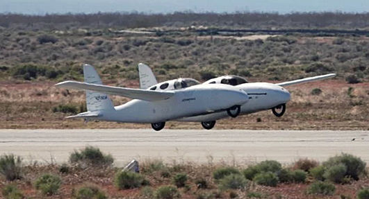
BiPod is an airplane car that can move on regular roads. The machine body is divided into two volumes. In each of the "floats" there is a place for the driver and hybrid drive, and the wings are able to fold into the opening between the buildings.
The device has a serial hybrid drive circuit. So in each fuselage placed 450 cc ICE, a rotating generator. Lithium batteries are located in the nose, and 15-kilowatt rear-wheel drive electric motors are located in the rear. Steered wheels in front.
PS: History often moves in a circle, and perhaps the transition to a bifurcated form of cars will be able to solve not only the problems of energy saving, but also the safety of pedestrians, stability in corners, and even survival in side impact. All this is still only concepts of ideas at the level of theory, and some analogies with already proven technologies, but as with the RUF idea, there is basically nothing complicated here - the only question is the need for such improvements.