March 14, 2019 at 10:06
Same as on the moon: reverse engineering of a hybrid op amp module
- Transfer
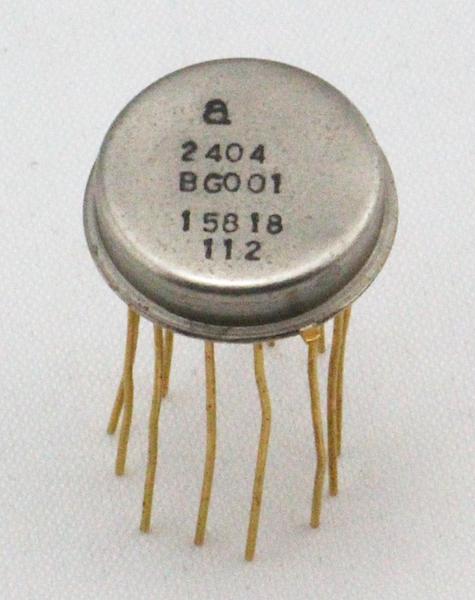
Recently, a mysterious electronic component in a metal case fell into my hands. It differed from the usual integrated circuit in appearance - it was flatter and more dimensional. What it is and what it is eaten with, it became clear after opening and reverse-engineering the circuit. Before me was an operational amplifier created for NASA in the 1960s using hybrid technology. It turns out that several significant people took part in the development of this component in the history of the development of semiconductors, and one of such operational amplifiers is located on the moon.
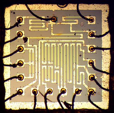
To understand the principle of operation of this component, I had to cut the upper part of the metal case with a jewelry saw, inside was an electrical circuit. The integrated circuit as such was absent, inside was a large hybrid module, assembled from separate tiny transistors on a ceramic substrate. In the photo below - on a ceramic substrate, grayish conductive paths, which looks like a printed circuit board. Separate silicon transistors (smaller shiny squares) are attached to the tracks on the substrate. Thin gold wires connect components to each other and connect the circuit to external contacts.
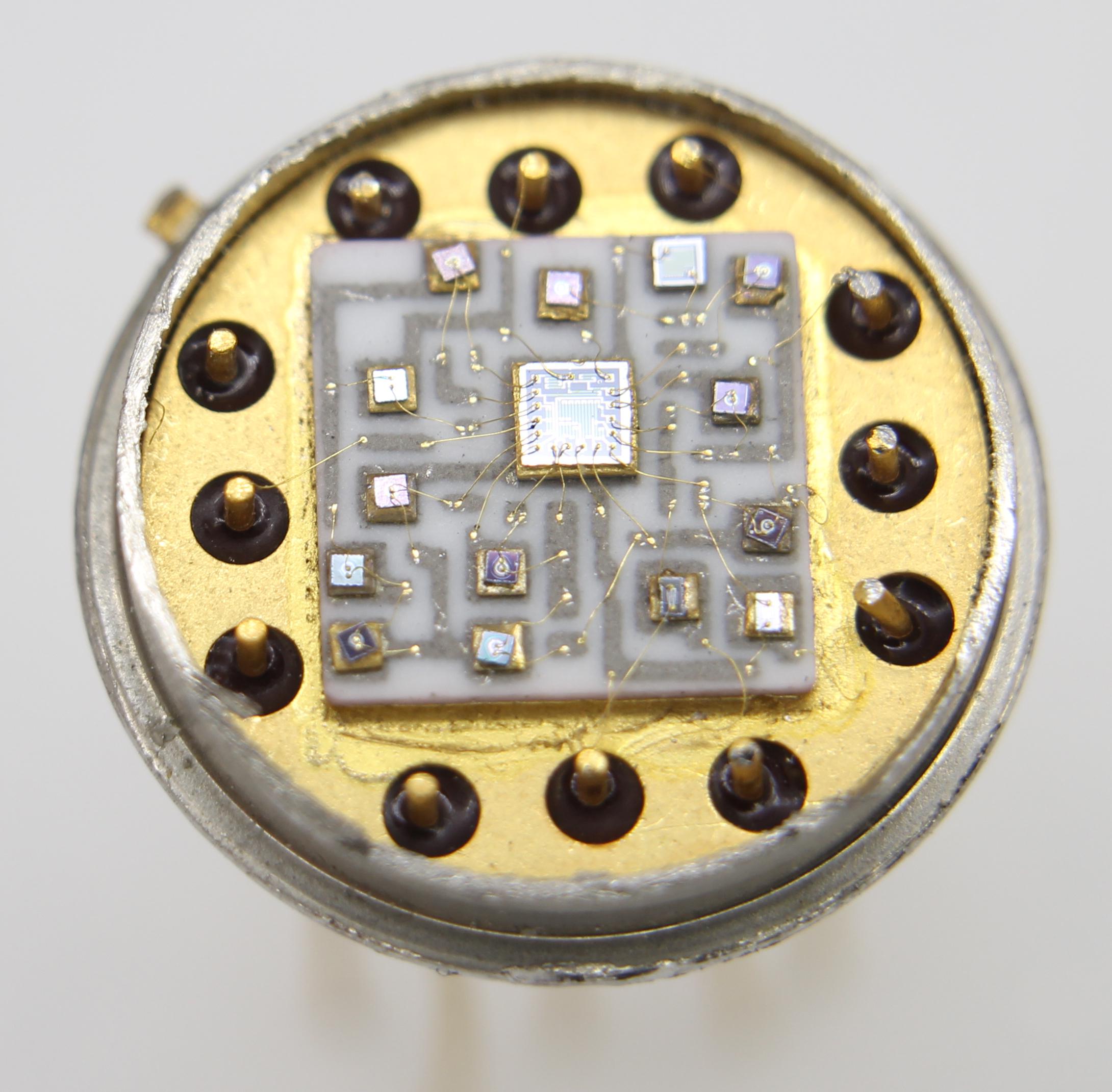
Hybrid integrated circuits were widely used in the 1960s before they were replaced with more complex integrated circuits. (For example, the popular IBM System / 360 computers (1964) were built from hybrid modules, not integrated circuits). Although operational amplifiers on integrated circuits were released in 1963, hybrids still remained at the peak of popularity until the 80s.
At first, I could not identify this part, so I asked Walt Jung, an expert on op-amps, for help. The numbers on the packaging indicated Amelco. This helped me track the history of the “secret” 2404BG operational amplifier manufactured by the now-forgotten Amelco. The item was sold in 1969 for $ 58.50 (equivalent to about $ 300 today). For comparison, now you can purchase a modern four-channel operational amplifier with a JFET input for less than 25 cents.
The operational amplifier is one of the most popular components of analog circuits; such flexibility and versatility provide it with such popularity. The operational amplifier receives two input voltages, reads them, multiplies the difference by a huge value (100,000 or more) and displays the result as a voltage. The op-amp was originally designed to perform mathematical operations by using voltage as an analog quantity.
In practice, the feedback loop makes the inputs almost equal; depending on the feedback scheme, the operational amplifier can be used, for example, as an amplifier, filter, integrator, differentiator or buffer. The key person at the beginning of the development of operational amplifiers was George Philbrick. He was the founder of the eponymous company George A. Philbrick Researches.
The successful commercial history of the operational amplifier began in 1952 when Philbrick introduced the K2-W op-amp , a dual-lamp module, which brought popularity to the product.
Now let's move on to Jean Hoerni, the founder of the above-mentioned company Amelco. Prehistory can be considered what happened in 1957, an event in the life of Silicon Valley. Eight young scientists, known as the “Betrayal Eight,” left Shockley Semiconductor. After leaving, they teamed up with businessman Sherman Fairchild and founded Fairchild Semiconductor, which led to the emergence of dozens of startups and the growth of the valley itself. Two of the treacherous eight Moore and Noyce later left Fairchild and founded Intel.
The physicist Jean Hoerni (Jean Horney), from the same treacherous eight, worked at Fairchild to improve transistors and achieved a success that exceeded all expectations. In 1959, he invented a planar transistor, and in 1959 he revolutionized the manufacture of semiconductors. Planar technology is essentially coating the surface of a silicon transistor with a thin layer of silicon oxide (like a cake coated with icing).
Interestingly, the transistors in the operational amplifier module (below) are identical in appearance to the original Horney planar transistors. The transistors of the 1970s and later look completely different, so it was a little strange for me to find Horney’s original design in this module.
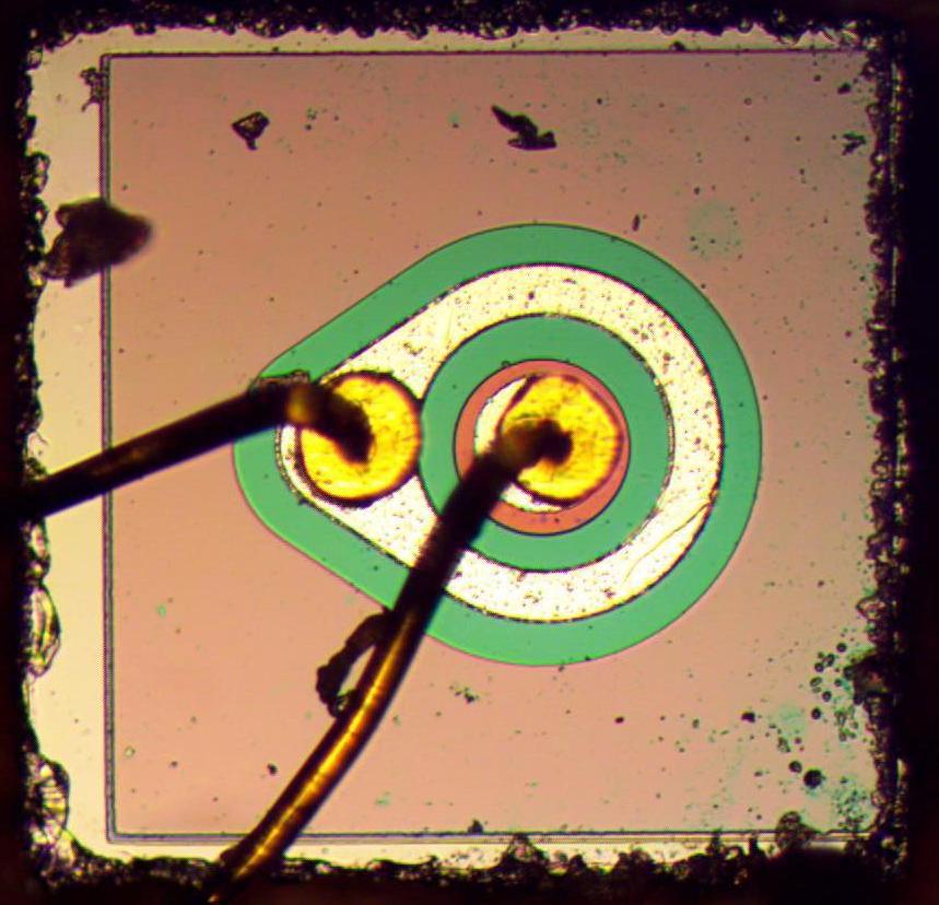
npn transistor inside a hybrid module. Tiny connecting wires are connected to the base and emitter, and the collector is on the underside.
Horney left Fairchild in 1961 and helped found a company called Amelco. The company focused on developing semiconductors for use in space, which did not directly compete with Fairchild. Linear (analog) integrated circuits were Amelco's main product as the company created opamps for Philbrick (a pioneering opamp company). In addition, Amelco manufactured discrete transistors using Horney planar technology. At Amelco, Horney developed a technique for constructing a JFET transistor using his planar process; these transistors have become one of Amelco's most popular products.
The main advantage of JFET is that the input current to the gate of the transistor is extremely small, and this is clearly an advantage for operational amplifiers. Amelco first used Horney's JFET in production with a high-performance op amp.
Bob Pease (Bob Pease) is a famous designer of analog circuits, connects these puzzles in history together. In the 1960s, Bob Pease developed operational amplifiers for Philbrick, including the FET Q25AH (1965) hybrid operational amplifier. Amelco launched this op amp for Philbrick. Bob Pease visited the company in order to help deal with some of the problems encountered in the production of the FET Q25AH. The essence of the story: during his visit, Bob Pease entered into a discussion with Amelco engineers, the topic of discussion was NASA's requirements for the release of a new low-power and low-noise amplifier. During the coffee break, Bob Pease managed to develop an operational amplifier that met NASA's stringent requirements. This operational amplifier was used in a seismic study, Apollo 12 left the op-amp on the moon in 1969, therefore, now one of these operational amplifiers is present on the celestial body. Amelco sold it as 2401BG.
As for the 2404BG I made out, its layout is very similar to the Bob Pease's 2401BG design, so I suspect that he designed these two products. Operational amplifier 2404BG was also lucky to get to the moon; it was used in a high voltage source while studying the composition of the lunar atmosphere (LACE). LACE is a mass spectrometer left on the moon during the third Apollo 17 Jay mission in 1972. (Using LACE, it was found that although the atmosphere is almost absent on the moon, it does have some helium, argon, and possibly neon, ammonia, methane, and carbon dioxide).
In 1966, Amelco teamed up with Philbrick to form the Teledyne Philbrick Nexus, which was eventually acquired by Microchip Technology in 2000. Among other things, Microchip manufactures the AVR microcontrollers used in the Arduino.
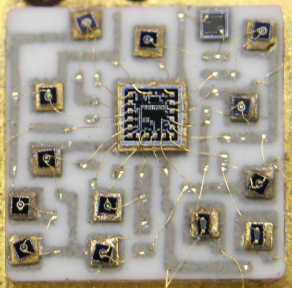
In this section, I will describe the design and layout of the 2404BG operational amplifier in more detail. In the photo below - a close-up shows the ceramic substrate and the components on it. Gray printed lines on ceramics are electrically conductive circuit tracks. Squares (most of them) are npn and pnp transistors, each on a separate silicon matrix. At the bottom of the crystal is a transistor collector connected to a ceramic track. Tiny gold wires are attached to the emitter and base of the transistor, connecting it to the circuit. The two rectangular transistors in the lower right corner are JFETs (field effect transistors with PN control junction). A large square in the middle is a set of resistors, another resistor is located in the upper right corner. Please note, unlike integrated circuits,
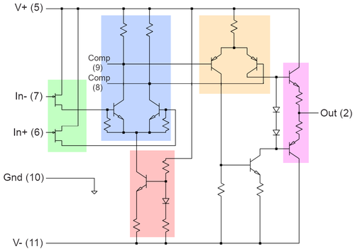
I reproduced the operational amplifier module circuit shown below. This circuit looks quite simple, since operational amplifiers work with about half of the components of the classic 741 op-amp. The inputs are buffered by JFETs (green). A differential pair (blue) amplifies the input by directing current on one side of the pair or on the other. The current source (red) generates a “tiny” direct current for the differential pair using a current mirror. A two-stage amplifier (orange) provides additional amplification. Output transistors (purple) work in the AV class. The remaining components (unpainted) supply the bias voltage of the output transistors. External capacitors on the contacts (8 and 9) prevent the op-amp from oscillation.
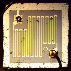
Most resistors are located on a single chip in the middle of the module; this crystal has a diameter of 1.7 mm (1/16 "). Zigzag shapes are thin-film resistors based on tantalum compounds deposited on an oxide-coated silicon wafer. (One of the advantages of hybrid circuits was better resistors). Resistance is proportional to the length therefore sinuous forms allowed placing more resistors on the matrix.Around the matrix there are metal substrates, connecting wires attached to the contacts connected the resistors to other parts of the circuit. attention to the small circle on the left near the upper right underlay: one of the innovations in Amelco is the designation of “target” in order to align the masks used for different layers of the chip.
A high-resistance resistor was required for the current source circuit, so a separate resistor matrix was used in it (below). A longer, thinner track was used in this resistor, which caused a higher resistance than in the resistor on the previous chip.
The crystal size for this resistor is 0.8 mm.
The photo below shows a field effect transistor with a control pn junction, which is used in an operational amplifier. Metal fingers connect to the source and drain areas. The transistor gate is connected from below. This design is almost identical to the first planar JFET invented by Horney in 1963. Initially, it was difficult to produce high-quality JFETs on an integrated circuit, which popularized the production of hybrid JFET operational amplifiers. It was not until 1974 that National Semiconductor engineers developed an ion implantation method for manufacturing high-quality JFET field effect transistors with a pn junction control. The method was called "BIFET" and was used to create more advanced integrated circuits for operational amplifiers.
The diagram below compares the structure of npn and pnp transistors in the module with the photos above and the cross section diagram below.
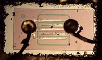
Field effect transistor inside the module. The matrix size is 0.6 × 0.3 mm.
How does the transistor begin? With a square silicon crystal, which is doped with impurities, which forms n and p regions (depending on the type of conductivity) with different characteristics. Under the microscope, it is seen that the silicon-doped n and p zones differ in color. A shiny metal layer with one electrical connection attached to a central emitter is visible from above. A second electrical connection is attached to the main area around the emitter; thanks to the teardrop shape, more space is allocated for fixing the main connection.
Bottom of the matrix is a collector that connects to the contacts on the ceramic substrate. The npn transistor follows a straight planar structure. The pnp transistor, however, required an additional conductive ring to operate the op amp at higher voltages.
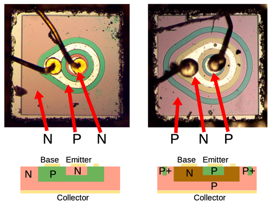
Comparison of npn and pnp transistors in a module
This component, which I accidentally uncovered, turned out to be more interesting than I expected. It intertwines the appearance of the first Philbrick operational amplifiers, the development of Bob Pease's analog circuit, the history of the now forgotten Amelco, NASA's scientific experiments on the Moon. The transistors inside this module were built using Horney's original planar designs, which allowed a look at the development of the planar process itself, which at one time revolutionized the world of semiconductors. Finally, this operational amplifier demonstrated the capabilities of hybrid technology, which is almost completely absent in integrated circuits.
1. The module was packaged in a standard 12-pin TO-8 package. Most integrated circuits are in the TO-5 metal casing, but larger hybrid circuits and space require more.
2. “15818” on the packaging is the CAGE code, the NATO identifier used to track suppliers. Initially, 15818 identified Amelko; due to the merger, this number is now owned by TelCom Semiconductor.
3. The book " The History of Semiconductor Technology " describes in great detail the stories of various semiconductor companies and people involved in this industry. A detailed history of operational amplifiers, including the development of the JFET op-amp in the 1970s, is Walt Jung's History of Operational Amplifiers .
4. Bob Pease has authored the popular Pease Porridge analog circuit heading . He also wrote books such as Troubleshooting Analog Circuits .
5. An article by Bob Pease “ What kind of thing is this - 2401BG? ” (P. 54) demonstrates the 2401BG scheme (below). Comparing the circuits, I came to the conclusion that 2401BG is very similar to the 2404BG that I investigated. (To simplify the comparison, I colorized the function blocks in accordance with 2404BG schema).
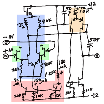
The main difference here is the output stage: 2401BG receives the output directly from the second pair, and for 2404BG the class of operation of the output stage of the amplifier is AB. 2401BG has a separate current mirror for input bases of npn transistors.
6. After I restored the op amp circuit, I managed to find a 1968 book with an Amelco hybrid op amp circuit. These two circuits are almost identical, except that in the circuit shown in the book there are two capacitors that are external in the 2404BG.
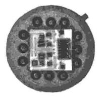
The image in the photograph of the hybrid op-amp in the book is different from the 2404BG I have studied. The part number is not indicated in the book (which is at least strange), so I suspect that it was only version 2404BG, which is under development.
7. " Jack Haenichen oral history / Oral History of Jack Hanikhan " and patent 3226611
Thank you for staying with us. Do you like our articles? Want to see more interesting materials? Support us by placing an order or recommending it to your friends, a 30% discount for Habr users on a unique analogue of entry-level servers that we invented for you: The whole truth about VPS (KVM) E5-2650 v4 (6 Cores) 10GB DDR4 240GB SSD 1Gbps from $ 20 or how to divide the server? (options are available with RAID1 and RAID10, up to 24 cores and up to 40GB DDR4).
VPS (KVM) E5-2650 v4 (6 Cores) 10GB DDR4 240GB SSD 1Gbps until the summer for free when paying for a period of six months, you can order here .
Dell R730xd 2 times cheaper? Only we have 2 x Intel Dodeca-Core Xeon E5-2650v4 128GB DDR4 6x480GB SSD 1Gbps 100 TV from $ 249in the Netherlands and the USA! Read about How to Build Infrastructure Bldg. class using Dell R730xd E5-2650 v4 servers costing 9,000 euros for a penny?
To understand the principle of operation of this component, I had to cut the upper part of the metal case with a jewelry saw, inside was an electrical circuit. The integrated circuit as such was absent, inside was a large hybrid module, assembled from separate tiny transistors on a ceramic substrate. In the photo below - on a ceramic substrate, grayish conductive paths, which looks like a printed circuit board. Separate silicon transistors (smaller shiny squares) are attached to the tracks on the substrate. Thin gold wires connect components to each other and connect the circuit to external contacts.
Hybrid integrated circuits were widely used in the 1960s before they were replaced with more complex integrated circuits. (For example, the popular IBM System / 360 computers (1964) were built from hybrid modules, not integrated circuits). Although operational amplifiers on integrated circuits were released in 1963, hybrids still remained at the peak of popularity until the 80s.
At first, I could not identify this part, so I asked Walt Jung, an expert on op-amps, for help. The numbers on the packaging indicated Amelco. This helped me track the history of the “secret” 2404BG operational amplifier manufactured by the now-forgotten Amelco. The item was sold in 1969 for $ 58.50 (equivalent to about $ 300 today). For comparison, now you can purchase a modern four-channel operational amplifier with a JFET input for less than 25 cents.
A bit of operational amplifier history
The operational amplifier is one of the most popular components of analog circuits; such flexibility and versatility provide it with such popularity. The operational amplifier receives two input voltages, reads them, multiplies the difference by a huge value (100,000 or more) and displays the result as a voltage. The op-amp was originally designed to perform mathematical operations by using voltage as an analog quantity.
In practice, the feedback loop makes the inputs almost equal; depending on the feedback scheme, the operational amplifier can be used, for example, as an amplifier, filter, integrator, differentiator or buffer. The key person at the beginning of the development of operational amplifiers was George Philbrick. He was the founder of the eponymous company George A. Philbrick Researches.
The successful commercial history of the operational amplifier began in 1952 when Philbrick introduced the K2-W op-amp , a dual-lamp module, which brought popularity to the product.
Now let's move on to Jean Hoerni, the founder of the above-mentioned company Amelco. Prehistory can be considered what happened in 1957, an event in the life of Silicon Valley. Eight young scientists, known as the “Betrayal Eight,” left Shockley Semiconductor. After leaving, they teamed up with businessman Sherman Fairchild and founded Fairchild Semiconductor, which led to the emergence of dozens of startups and the growth of the valley itself. Two of the treacherous eight Moore and Noyce later left Fairchild and founded Intel.
The physicist Jean Hoerni (Jean Horney), from the same treacherous eight, worked at Fairchild to improve transistors and achieved a success that exceeded all expectations. In 1959, he invented a planar transistor, and in 1959 he revolutionized the manufacture of semiconductors. Planar technology is essentially coating the surface of a silicon transistor with a thin layer of silicon oxide (like a cake coated with icing).
Interestingly, the transistors in the operational amplifier module (below) are identical in appearance to the original Horney planar transistors. The transistors of the 1970s and later look completely different, so it was a little strange for me to find Horney’s original design in this module.
npn transistor inside a hybrid module. Tiny connecting wires are connected to the base and emitter, and the collector is on the underside.
Horney left Fairchild in 1961 and helped found a company called Amelco. The company focused on developing semiconductors for use in space, which did not directly compete with Fairchild. Linear (analog) integrated circuits were Amelco's main product as the company created opamps for Philbrick (a pioneering opamp company). In addition, Amelco manufactured discrete transistors using Horney planar technology. At Amelco, Horney developed a technique for constructing a JFET transistor using his planar process; these transistors have become one of Amelco's most popular products.
The main advantage of JFET is that the input current to the gate of the transistor is extremely small, and this is clearly an advantage for operational amplifiers. Amelco first used Horney's JFET in production with a high-performance op amp.
Bob Pease (Bob Pease) is a famous designer of analog circuits, connects these puzzles in history together. In the 1960s, Bob Pease developed operational amplifiers for Philbrick, including the FET Q25AH (1965) hybrid operational amplifier. Amelco launched this op amp for Philbrick. Bob Pease visited the company in order to help deal with some of the problems encountered in the production of the FET Q25AH. The essence of the story: during his visit, Bob Pease entered into a discussion with Amelco engineers, the topic of discussion was NASA's requirements for the release of a new low-power and low-noise amplifier. During the coffee break, Bob Pease managed to develop an operational amplifier that met NASA's stringent requirements. This operational amplifier was used in a seismic study, Apollo 12 left the op-amp on the moon in 1969, therefore, now one of these operational amplifiers is present on the celestial body. Amelco sold it as 2401BG.
As for the 2404BG I made out, its layout is very similar to the Bob Pease's 2401BG design, so I suspect that he designed these two products. Operational amplifier 2404BG was also lucky to get to the moon; it was used in a high voltage source while studying the composition of the lunar atmosphere (LACE). LACE is a mass spectrometer left on the moon during the third Apollo 17 Jay mission in 1972. (Using LACE, it was found that although the atmosphere is almost absent on the moon, it does have some helium, argon, and possibly neon, ammonia, methane, and carbon dioxide).
In 1966, Amelco teamed up with Philbrick to form the Teledyne Philbrick Nexus, which was eventually acquired by Microchip Technology in 2000. Among other things, Microchip manufactures the AVR microcontrollers used in the Arduino.
Inside a hybrid op amp
In this section, I will describe the design and layout of the 2404BG operational amplifier in more detail. In the photo below - a close-up shows the ceramic substrate and the components on it. Gray printed lines on ceramics are electrically conductive circuit tracks. Squares (most of them) are npn and pnp transistors, each on a separate silicon matrix. At the bottom of the crystal is a transistor collector connected to a ceramic track. Tiny gold wires are attached to the emitter and base of the transistor, connecting it to the circuit. The two rectangular transistors in the lower right corner are JFETs (field effect transistors with PN control junction). A large square in the middle is a set of resistors, another resistor is located in the upper right corner. Please note, unlike integrated circuits,
I reproduced the operational amplifier module circuit shown below. This circuit looks quite simple, since operational amplifiers work with about half of the components of the classic 741 op-amp. The inputs are buffered by JFETs (green). A differential pair (blue) amplifies the input by directing current on one side of the pair or on the other. The current source (red) generates a “tiny” direct current for the differential pair using a current mirror. A two-stage amplifier (orange) provides additional amplification. Output transistors (purple) work in the AV class. The remaining components (unpainted) supply the bias voltage of the output transistors. External capacitors on the contacts (8 and 9) prevent the op-amp from oscillation.
Most resistors are located on a single chip in the middle of the module; this crystal has a diameter of 1.7 mm (1/16 "). Zigzag shapes are thin-film resistors based on tantalum compounds deposited on an oxide-coated silicon wafer. (One of the advantages of hybrid circuits was better resistors). Resistance is proportional to the length therefore sinuous forms allowed placing more resistors on the matrix.Around the matrix there are metal substrates, connecting wires attached to the contacts connected the resistors to other parts of the circuit. attention to the small circle on the left near the upper right underlay: one of the innovations in Amelco is the designation of “target” in order to align the masks used for different layers of the chip.
A high-resistance resistor was required for the current source circuit, so a separate resistor matrix was used in it (below). A longer, thinner track was used in this resistor, which caused a higher resistance than in the resistor on the previous chip.
The crystal size for this resistor is 0.8 mm.
The photo below shows a field effect transistor with a control pn junction, which is used in an operational amplifier. Metal fingers connect to the source and drain areas. The transistor gate is connected from below. This design is almost identical to the first planar JFET invented by Horney in 1963. Initially, it was difficult to produce high-quality JFETs on an integrated circuit, which popularized the production of hybrid JFET operational amplifiers. It was not until 1974 that National Semiconductor engineers developed an ion implantation method for manufacturing high-quality JFET field effect transistors with a pn junction control. The method was called "BIFET" and was used to create more advanced integrated circuits for operational amplifiers.
The diagram below compares the structure of npn and pnp transistors in the module with the photos above and the cross section diagram below.
Field effect transistor inside the module. The matrix size is 0.6 × 0.3 mm.
How does the transistor begin? With a square silicon crystal, which is doped with impurities, which forms n and p regions (depending on the type of conductivity) with different characteristics. Under the microscope, it is seen that the silicon-doped n and p zones differ in color. A shiny metal layer with one electrical connection attached to a central emitter is visible from above. A second electrical connection is attached to the main area around the emitter; thanks to the teardrop shape, more space is allocated for fixing the main connection.
Bottom of the matrix is a collector that connects to the contacts on the ceramic substrate. The npn transistor follows a straight planar structure. The pnp transistor, however, required an additional conductive ring to operate the op amp at higher voltages.
Comparison of npn and pnp transistors in a module
Conclusion
This component, which I accidentally uncovered, turned out to be more interesting than I expected. It intertwines the appearance of the first Philbrick operational amplifiers, the development of Bob Pease's analog circuit, the history of the now forgotten Amelco, NASA's scientific experiments on the Moon. The transistors inside this module were built using Horney's original planar designs, which allowed a look at the development of the planar process itself, which at one time revolutionized the world of semiconductors. Finally, this operational amplifier demonstrated the capabilities of hybrid technology, which is almost completely absent in integrated circuits.
Notes and links
1. The module was packaged in a standard 12-pin TO-8 package. Most integrated circuits are in the TO-5 metal casing, but larger hybrid circuits and space require more.
2. “15818” on the packaging is the CAGE code, the NATO identifier used to track suppliers. Initially, 15818 identified Amelko; due to the merger, this number is now owned by TelCom Semiconductor.
3. The book " The History of Semiconductor Technology " describes in great detail the stories of various semiconductor companies and people involved in this industry. A detailed history of operational amplifiers, including the development of the JFET op-amp in the 1970s, is Walt Jung's History of Operational Amplifiers .
4. Bob Pease has authored the popular Pease Porridge analog circuit heading . He also wrote books such as Troubleshooting Analog Circuits .
5. An article by Bob Pease “ What kind of thing is this - 2401BG? ” (P. 54) demonstrates the 2401BG scheme (below). Comparing the circuits, I came to the conclusion that 2401BG is very similar to the 2404BG that I investigated. (To simplify the comparison, I colorized the function blocks in accordance with 2404BG schema).
The main difference here is the output stage: 2401BG receives the output directly from the second pair, and for 2404BG the class of operation of the output stage of the amplifier is AB. 2401BG has a separate current mirror for input bases of npn transistors.
6. After I restored the op amp circuit, I managed to find a 1968 book with an Amelco hybrid op amp circuit. These two circuits are almost identical, except that in the circuit shown in the book there are two capacitors that are external in the 2404BG.
The image in the photograph of the hybrid op-amp in the book is different from the 2404BG I have studied. The part number is not indicated in the book (which is at least strange), so I suspect that it was only version 2404BG, which is under development.
7. " Jack Haenichen oral history / Oral History of Jack Hanikhan " and patent 3226611
Thank you for staying with us. Do you like our articles? Want to see more interesting materials? Support us by placing an order or recommending it to your friends, a 30% discount for Habr users on a unique analogue of entry-level servers that we invented for you: The whole truth about VPS (KVM) E5-2650 v4 (6 Cores) 10GB DDR4 240GB SSD 1Gbps from $ 20 or how to divide the server? (options are available with RAID1 and RAID10, up to 24 cores and up to 40GB DDR4).
VPS (KVM) E5-2650 v4 (6 Cores) 10GB DDR4 240GB SSD 1Gbps until the summer for free when paying for a period of six months, you can order here .
Dell R730xd 2 times cheaper? Only we have 2 x Intel Dodeca-Core Xeon E5-2650v4 128GB DDR4 6x480GB SSD 1Gbps 100 TV from $ 249in the Netherlands and the USA! Read about How to Build Infrastructure Bldg. class using Dell R730xd E5-2650 v4 servers costing 9,000 euros for a penny?