DIY thermal imager on Raspberry PI or “It seems now I know what I will do this summer”
Hello!
Winter has come, and with it the task to check the insulating properties of the
MLX90640. What is it?
And this, in fact, a thermal imaging matrix with a microcontroller on board. Production of a previously unknown company Melexis. Thermal imaging matrix has a dimension of 32 by 24 pixels. This is not much, but when interpolating an image, it seems like enough to see at least something.
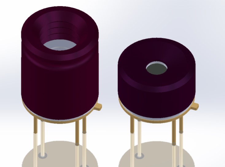
The sensor is available in two versions, the body of which differ in the viewing angle of the matrix. A more stocky design A observes the surrounding world at an angle of 110 (horizontal) by 75 (vertical) degrees. B - under 55 to 37.5 degrees, respectively. The case of the device has only four outputs - two for power, two for communication with the control device via the I2C interface. Datasheet for those interested can be downloaded here .
What then is the GY-MCU90640?
The Chinese comrades put the MLX90640 on the board with another microcontroller on board (STM32F103). Apparently, for easier management of the matrix. All this household is called GY-MCU90640. And it is worth at the time of purchase (end of December 2018) in the region of 5 thousand rubles. It looks like this:

As you can see, there are two types of boards, with a narrow or wide-angle version of the sensor on board.
Which version is best for you? A good question, unfortunately, it came to me only after the module was already ordered and received. For some reason, at the time of the order, I did not pay attention to these nuances. And in vain.
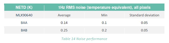
A wider version will be good on self-propelled robots or in security systems (the field of view will be larger). According to the datasheet, it also has less noise and greater measurement accuracy.
But for visualization tasks, I would recommend a more “long-range” version B. For one very significant reason. In the future, when shooting, you can expand it (manually or on a platform with a drive) and make composite "photos", thereby increasing the more than a modest resolution of 32 by 24 pixels. To collect thermal images 64 by 96 pixels, for example ... Well, okay, in the future the text will be from my wide-angle version A.
Connect to Raspberry PI
You can control the thermal imaging module in two ways:
- Short-circuit the “SET” jumper on the board and, via I2C, contact the internal MLX90640 microcontroller directly.
- Leave the jumper alone and communicate with the module through a similar interface installed on the STM32F103 board via RS-232.
If you are writing in C ++, it will probably be more convenient to ignore the extra microcontroller, short the jumper and use the API from the manufacturer, which lies here .
Modest pytonists, too, can go the first way. It seems like there are a couple of libraries in Python ( here and here ). But unfortunately, none of them earned my turn.
Advanced pythonists can, in principle, write a module control driver on Python. The procedure for obtaining the frame is described in detail in the datasheet. But then you have to prescribe all calibration procedures, which seems a bit cumbersome. So I had to go the second way. He was moderately thorny, but quite passable.
Thanks to the foresight of the Chinese engineers or just a lucky coincidence, the handkerchief turned out to be a very good arrangement of conclusions:
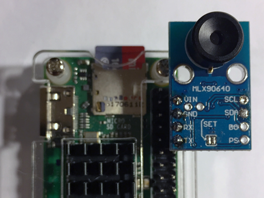
All that was left was to put the shoe and insert the handkerchief into the raspberry plug. The board is equipped with a 5 to 3 Volt converter, so Raspberry's delicate Rx and Tx do not seem to threaten anything.
It is necessary to add that the connection according to the first option is also possible, but it requires more labor and soldering skills. The board must be placed on the other side of the Raspberry connector (shown in the title photo of this post).
Soft
On a well-known Chinese website, the following miracle is offered to access GY-MCU90640:
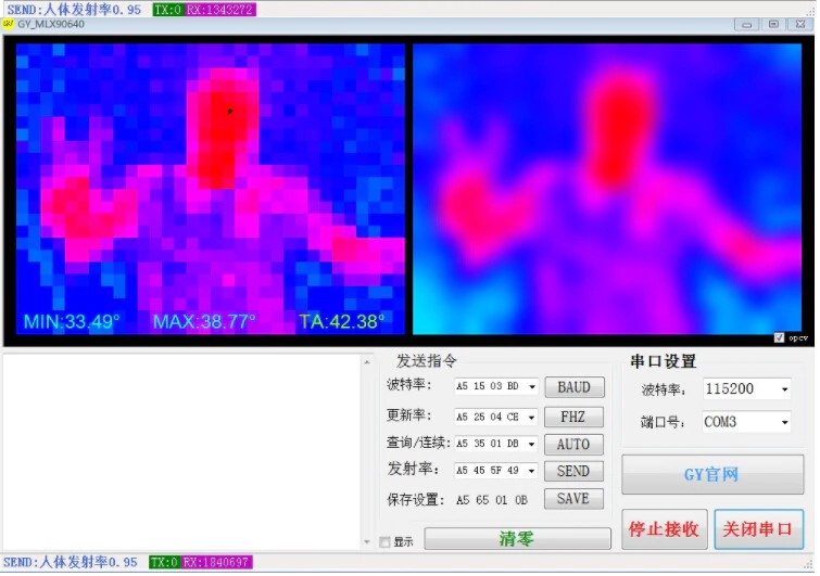
Apparently, there must be some description of the interaction protocol with an on-board microcontroller, according to which this software works! After a brief conversation with the handkerchief seller (respect to these respected gentlemen), this protocol was sent to me. He was in pdf and in pure Chinese.
Thanks to Google’s translator and active copy-pasting in about an hour and a half, the protocol was decrypted, anyone can get acquainted with it on Github . It turned out that the shawl understands six basic commands, among which there is a frame request on the COM port.
Each pixel of the matrix is, in fact, the temperature value of the object on which this pixel is looking. Temperature value in degrees Celsius multiplied by 100 (two-byte number). Actually, there is even a special mode in which the shawl will send frames from the matrix to Raspberry 4 times per second.
The script for thermal imaging is here:
"""MIT License
Copyright (c) 2019
Permission is hereby granted, free of charge, to any person obtaining a copy
of this software and associated documentation files (the "Software"), to deal
in the Software without restriction, including without limitation the rights
to use, copy, modify, merge, publish, distribute, sublicense, and/or sell
copies of the Software, and to permit persons to whom the Software is
furnished to do so, subject to the following conditions:
The above copyright notice and this permission notice shall be included in all
copies or substantial portions of the Software.
THE SOFTWARE IS PROVIDED "AS IS", WITHOUT WARRANTY OF ANY KIND, EXPRESS OR
IMPLIED, INCLUDING BUT NOT LIMITED TO THE WARRANTIES OF MERCHANTABILITY,
FITNESS FOR A PARTICULAR PURPOSE AND NONINFRINGEMENT. IN NO EVENT SHALL THE
AUTHORS OR COPYRIGHT HOLDERS BE LIABLE FOR ANY CLAIM, DAMAGES OR OTHER
LIABILITY, WHETHER IN AN ACTION OF CONTRACT, TORT OR OTHERWISE, ARISING FROM,
OUT OF OR IN CONNECTION WITH THE SOFTWARE OR THE USE OR OTHER DEALINGS IN THE
SOFTWARE."""import serial, time
import datetime as dt
import numpy as np
import cv2
# function to get Emissivity from MCUdefget_emissivity():
	ser.write(serial.to_bytes([0xA5,0x55,0x01,0xFB]))
	read = ser.read(4)
	return read[2]/100# function to get temperatures from MCU (Celsius degrees x 100)defget_temp_array(d):# getting ambient temperature
	T_a = (int(d[1540]) + int(d[1541])*256)/100# getting raw array of pixels temperature
	raw_data = d[4:1540]
	T_array = np.frombuffer(raw_data, dtype=np.int16)
	return T_a, T_array
# function to convert temperatures to pixels on imagedeftd_to_image(f):
	norm = np.uint8((f/100 - Tmin)*255/(Tmax-Tmin))
	norm.shape = (24,32)
	return norm
########################### Main cycle ################################## Color map range
Tmax = 40
Tmin = 20print ('Configuring Serial port')
ser = serial.Serial ('/dev/serial0')
ser.baudrate = 115200# set frequency of module to 4 Hz
ser.write(serial.to_bytes([0xA5,0x25,0x01,0xCB]))
time.sleep(0.1)
# Starting automatic data colection
ser.write(serial.to_bytes([0xA5,0x35,0x02,0xDC]))
t0 = time.time()
try:
	whileTrue:
		# waiting for data frame
		data = ser.read(1544)
		# The data is ready, let's handle it!
		Ta, temp_array = get_temp_array(data)
		ta_img = td_to_image(temp_array)
		# Image processing
		img = cv2.applyColorMap(ta_img, cv2.COLORMAP_JET)
		img = cv2.resize(img, (320,240), interpolation = cv2.INTER_CUBIC)
		img = cv2.flip(img, 1)
		text = 'Tmin = {:+.1f} Tmax = {:+.1f} FPS = {:.2f}'.format(temp_array.min()/100, temp_array.max()/100, 1/(time.time() - t0))
		cv2.putText(img, text, (5, 15), cv2.FONT_HERSHEY_SIMPLEX, 0.45, (0, 0, 0), 1)
		cv2.imshow('Output', img)
		# if 's' is pressed - saving of picture
		key = cv2.waitKey(1) & 0xFFif key == ord("s"):
			fname = 'pic_' + dt.datetime.now().strftime('%Y-%m-%d_%H-%M-%S') + '.jpg'
			cv2.imwrite(fname, img)
			print('Saving image ', fname)
		t0 = time.time()
except KeyboardInterrupt:
	# to terminate the cycle
	ser.write(serial.to_bytes([0xA5,0x35,0x01,0xDB]))
	ser.close()
	cv2.destroyAllWindows()
	print(' Stopped')
# just in case
ser.close()
cv2.destroyAllWindows()
results
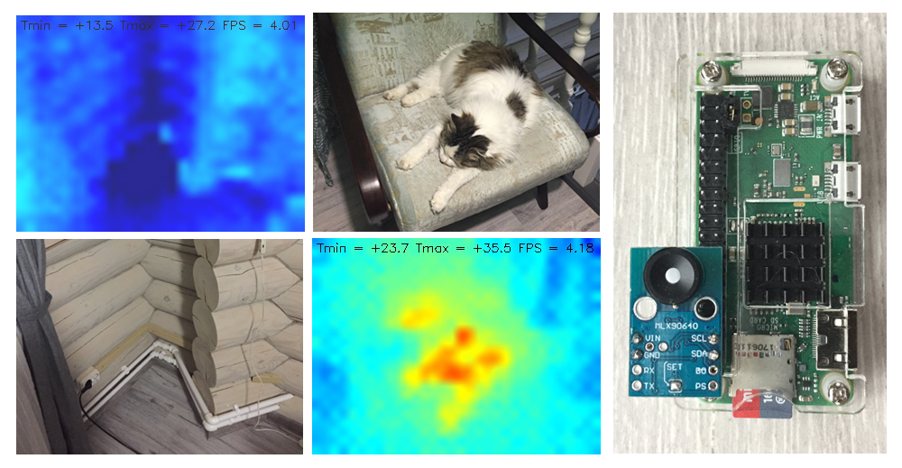
The script polls the thermal imaging matrix and displays the frames on the monitor console to which the Raspberry PI is connected, 4 times per second. This is enough to not experience great discomfort when shooting objects. To render the frame, the OpenCV package is used. When you click on the "s" button in the folder with the script, thermal imaging "heat maps" are saved in jpg format.
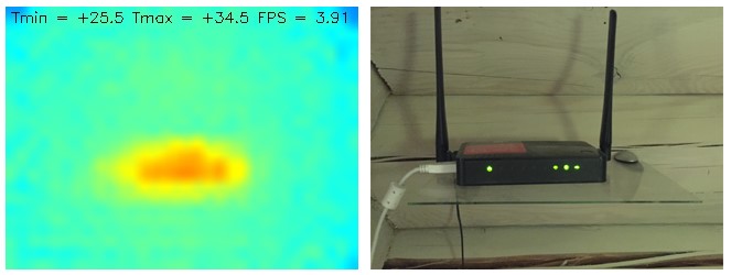
For more informative, I derived the minimum and maximum temperature on the frame. That is, looking at the color, you can see what about the temperature of the most heated or cooled objects. The measurement error is about a degree from the larger side. Thermal range is set from 20 to 40 degrees. Exit the script by pressing Ctrl + C.
The script works about the same on both the Raspberry Pi Zero W and the Pi 3 B +. I installed the VNC server on a smartphone. Thus, by picking up the raspberries connected to the powerbank and smarfton with running VNC, you can get a portable thermal imager with the ability to save thermal images. Perhaps this is not very convenient, but quite functional.
After the first start, incorrect measurement of the maximum temperature is possible. In this case, you need to exit the script and run it again.
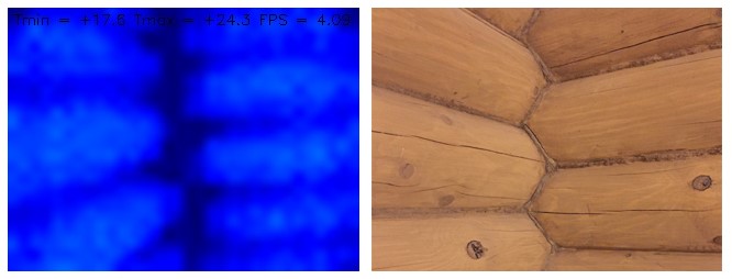
That's all for today. The experiment with a homemade thermal imager turned out to be successful. With the help of this device it is quite possible to conduct a thermal imaging survey of the house on your own, for example If someone has additional thoughts about the areas of application of such pieces, welcome to the comments.
All successful work week and see you soon!
UPD: In the comments I was asked to take a picture of the house from the street. I post it here. Due to the lower temperature contrast than in the room, the pictures were not very informative. In the photo above, the house is entirely on both sides. On the bottom - photos of different windows.
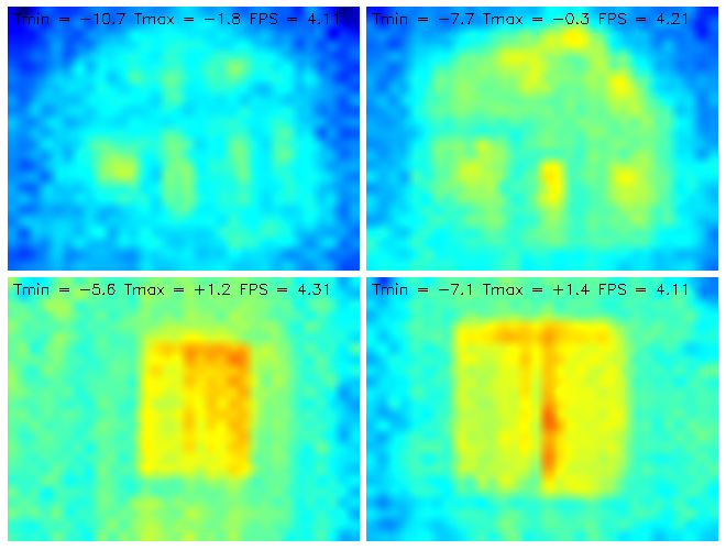
In the code I changed only the temperature range. Instead of +20 ... +40, he set -10 ... + 5.