How Peer Zoning simplified our lives and helped balance the load of EMC VPLEX
Our storage infrastructure had two problems. Firstly, this is 960 “Single initiator - Single target” zones on the SAN, which complicated the administration of the SAN network. And secondly, the unbalanced load on the directors of EMC VPLEX. Thanks to the introduction of Peer zoning, we reduced the number of zones by 120 times, saved engineers twice the time and got a more or less even load of EMC VPLEX directors. Further I will tell how we made it.
In the customer's infrastructure:
On the diagram, it looks like this:
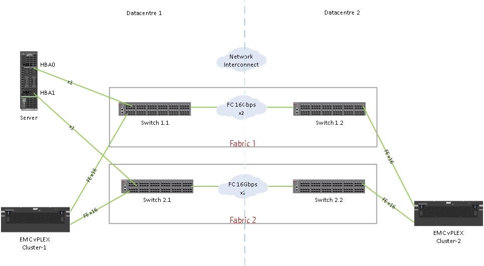
The diagram is simplified - it shows only one server and its connection to the factories (the other servers are connected in the same way), only the front-end (FE) ports from EMC VPLEX are shown, the back-end storage is not shown and the EMC VPLEX engines and directors are not shown.
In the current configuration:
Total 4 * 2 * 4 = 32 FE ports, 16 of which, for fault tolerance, are connected to Fabric1 and the other 16 ports are connected to Fabric2.
Each server has two HBAs: HBA0 and HBA1. Connection to the factories is similar - for fault tolerance, HBA0 is connected to Fabric1, HBA1 to Fabric2.
According to the best practices of EMC VPLEX, each HBA server has a zone for one FE-port of each of the four engines. When we used Single initiator zoning, it was 4 zones per factory, only 8 paths through two factories for one server.
In the figure it looks like this:
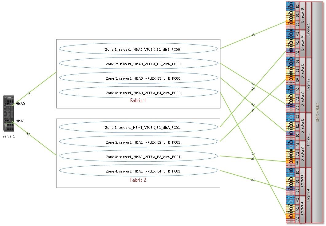
A year ago, we used Single initiator zoning and did zoning on the principle of “Single initiator - Single target” in each zone. And so, if you count, there were 4 zones * 120 servers = 480 zones per one factory, and 8 zones * 120 servers = 960 zones respectively on two factories. The introduction of Peer Zoning helped to reduce the number of zones by 120 (!) Times, reducing them to 8 - by 4 peer-zones in each factory.
Unlike Single initiator zoning, Peer-zone consists of principal (target) and members (initiators). Members within the same Peer-zone interact only with the principal. Moreover, each member does not see another member. The same principal: one principal does not interact with another principal.
We combined the FE ports of the VPLEX into groups and created 4 Peer zones in each factory.
How we implemented it
To comply with all EMC best practices, we did it as follows.
In PEER_VPLEX_Fabric1_Group1 zone as the principal entered VPLEX ports:
Engine1_directorB_FC01
Engine2_directorA_FC01
Engine3_directorB_FC01
Engine4_directorA_FC01
In PEER_VPLEX_Fabric1_Group2 zone as the principal entered VPLEX ports:
Engine1_directorA_FC01
Engine2_directorB_FC01
Engine3_directorA_FC01
Engine4_directorB_FC01
In PEER_VPLEX_Fabric2_Group1 zone as the principal entered VPLEX ports:
Engine1_directorA_FC00
Engine2_directorB_FC00
Engine3_directorA_FC00
Engine4_directorB_FC00
And so on.
Schematically:
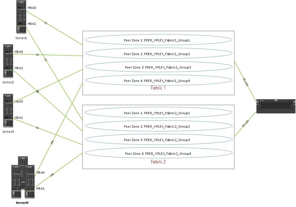
Now, when adding new servers to the SAN, it is enough to add the WWN of new servers to the existing Peer zones.
As a result of the introduction of Peer zoning, the administration of the SAN network zones has been greatly simplified, which at least twice saved the time of engineers.
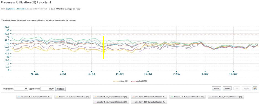
And, besides, it was possible to achieve load balancing directors.
Below are the Current Utilization charts taken from EMC ViPR SRM each of the directors of both EMC VPLEX cluster-1 and cluster-2.
Yellow marks the start date of the phased implementation of PeerZoning on the front-end.

In the customer's infrastructure:
- one EMC VPLEX in each data center in Metro configuration;
- total of 120 servers connected to them;
- Two SAN factories, each with two Brocade SAN switches.
On the diagram, it looks like this:
The diagram is simplified - it shows only one server and its connection to the factories (the other servers are connected in the same way), only the front-end (FE) ports from EMC VPLEX are shown, the back-end storage is not shown and the EMC VPLEX engines and directors are not shown.
In the current configuration:
- each EMC VPLEX has 4 engines
- each engine has two directors
- each director of 4 FE ports.
Total 4 * 2 * 4 = 32 FE ports, 16 of which, for fault tolerance, are connected to Fabric1 and the other 16 ports are connected to Fabric2.
Each server has two HBAs: HBA0 and HBA1. Connection to the factories is similar - for fault tolerance, HBA0 is connected to Fabric1, HBA1 to Fabric2.
According to the best practices of EMC VPLEX, each HBA server has a zone for one FE-port of each of the four engines. When we used Single initiator zoning, it was 4 zones per factory, only 8 paths through two factories for one server.
In the figure it looks like this:
A year ago, we used Single initiator zoning and did zoning on the principle of “Single initiator - Single target” in each zone. And so, if you count, there were 4 zones * 120 servers = 480 zones per one factory, and 8 zones * 120 servers = 960 zones respectively on two factories. The introduction of Peer Zoning helped to reduce the number of zones by 120 (!) Times, reducing them to 8 - by 4 peer-zones in each factory.
Unlike Single initiator zoning, Peer-zone consists of principal (target) and members (initiators). Members within the same Peer-zone interact only with the principal. Moreover, each member does not see another member. The same principal: one principal does not interact with another principal.
We combined the FE ports of the VPLEX into groups and created 4 Peer zones in each factory.
How we implemented it
To comply with all EMC best practices, we did it as follows.
In PEER_VPLEX_Fabric1_Group1 zone as the principal entered VPLEX ports:
Engine1_directorB_FC01
Engine2_directorA_FC01
Engine3_directorB_FC01
Engine4_directorA_FC01
In PEER_VPLEX_Fabric1_Group2 zone as the principal entered VPLEX ports:
Engine1_directorA_FC01
Engine2_directorB_FC01
Engine3_directorA_FC01
Engine4_directorB_FC01
In PEER_VPLEX_Fabric2_Group1 zone as the principal entered VPLEX ports:
Engine1_directorA_FC00
Engine2_directorB_FC00
Engine3_directorA_FC00
Engine4_directorB_FC00
And so on.
Schematically:
Now, when adding new servers to the SAN, it is enough to add the WWN of new servers to the existing Peer zones.
As a result of the introduction of Peer zoning, the administration of the SAN network zones has been greatly simplified, which at least twice saved the time of engineers.
And, besides, it was possible to achieve load balancing directors.
Below are the Current Utilization charts taken from EMC ViPR SRM each of the directors of both EMC VPLEX cluster-1 and cluster-2.
Yellow marks the start date of the phased implementation of PeerZoning on the front-end.