DIY Homemade Power Meter DIY Power Meter
I have been fond of cycling for a long time, but in the last year I was interested not only in skiing as such, but also in improving my results, in sports terms. Studying all sorts of techniques, training plans and aids, almost every time it came down to the need (or at least great benefit) for training a device like the Power meter.
And I decided to collect this ...
Why do I need a powerful meter?
This device measures the power that you apply to the pedals. Knowing the power helps a lot in training: you can track your progress over time, it allows you to accurately understand what effort you make when riding - and are you now driving so slowly because you have not slept well, or is the road really going uphill? And gives many other useful features.
Why make a powerful meter yourself, instead of buying?
1 - the price of existing samples is simply monstrous , the cheapest samples cost 600 American money (and on average about 1000), not including delivery, customs clearance and a head unit (a screen / computer that displays data, which will cost at least $ 100 )
2 - because I'm interested in designing something and watching how it works :)
So, let's start.
The principle of operation
There are many options to measure power, I chose one of them: measure the bend of the connecting rod from the pressure of the foot on the pedal.
Material base
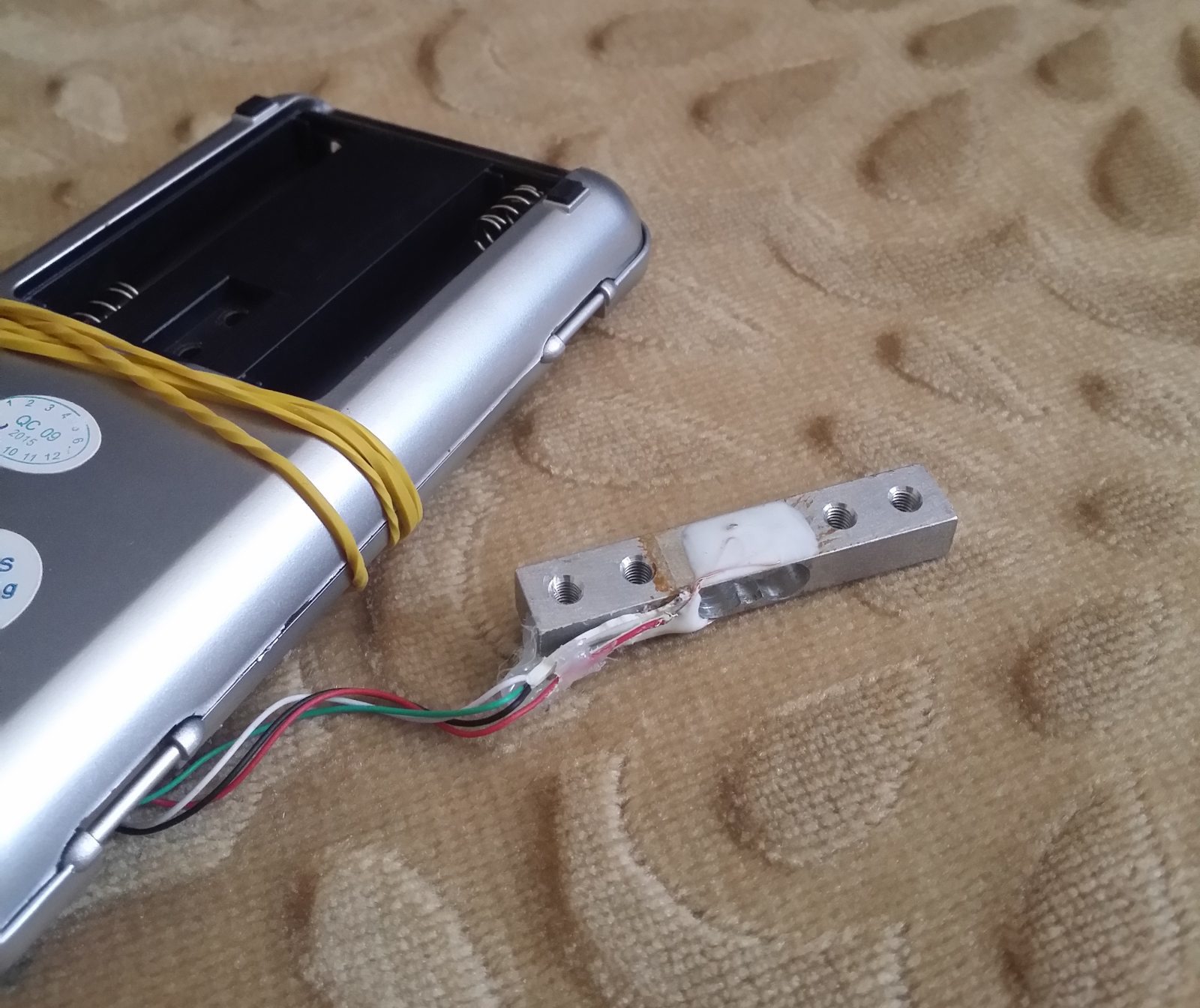
I have been searching for a long time, what kind of sensitive element is available and can be used in such a device? Various options were considered - optical sensors, piezoelectric sensors, measuring the frequency of transmitted sound, but came to the conclusion that it would be easiest to use a bridge load sensor. Having started looking for where it can be purchased, I came to the disappointing conclusion that it was either expensive or ordered in China and waited from two weeks to two months. But climbing on one local bulletin board, I found a proposal for the sale of scales with an accuracy of 0.01 grams and not at all expensive. I was not yet sure that such a sensor was in the balance, but I ordered it anyway.

It was very
unfortunate to disassemble, although they are inexpensive. Having opened the scales, I loaded them with exactly what I was looking for, a bridge load sensor!
A short experiment was conducted, with the help of which I found out whether such a sensor can measure the bend of the connecting rod.

Really works!
Since in the balance all electronic components were under one “drop”, then the entire electronic body kit had to be searched and done by yourself.
The list of parts that I chose :
1 - the amplifier of the HX711 weight sensor - a bridge sensor is connected to it, the output is a certain value, already digitally, convenient for processing
2 - the cadence sensor - reed switch, - is needed to measure the speed of the pedals, so how easy it is to measure the applied force to the pedals is not enough to measure the power, you need to know the rotation speed
3 - transmitter, bluetooth module HC-05, to transfer data to a computer or phone
4 - Arduino nano controller - the brains of the device process the data received from the amplifier and erkona data is sent to the transmitter
5 - power supply - since all modules require 5V power, you need a power source and a converter, the source decided to take the battery compartment from the scales from which the load was removed and putting it
all together I got the following picture

Nda, and how to put everything on the pedal ?
I had to fit everything in the case from all the same weights, it barely worked out. I am far from wiring and etching boards, so I just soldered wires to the legs of the microcircuits. If you breed a separate board and install smd components on it, you will, of course, get much less.
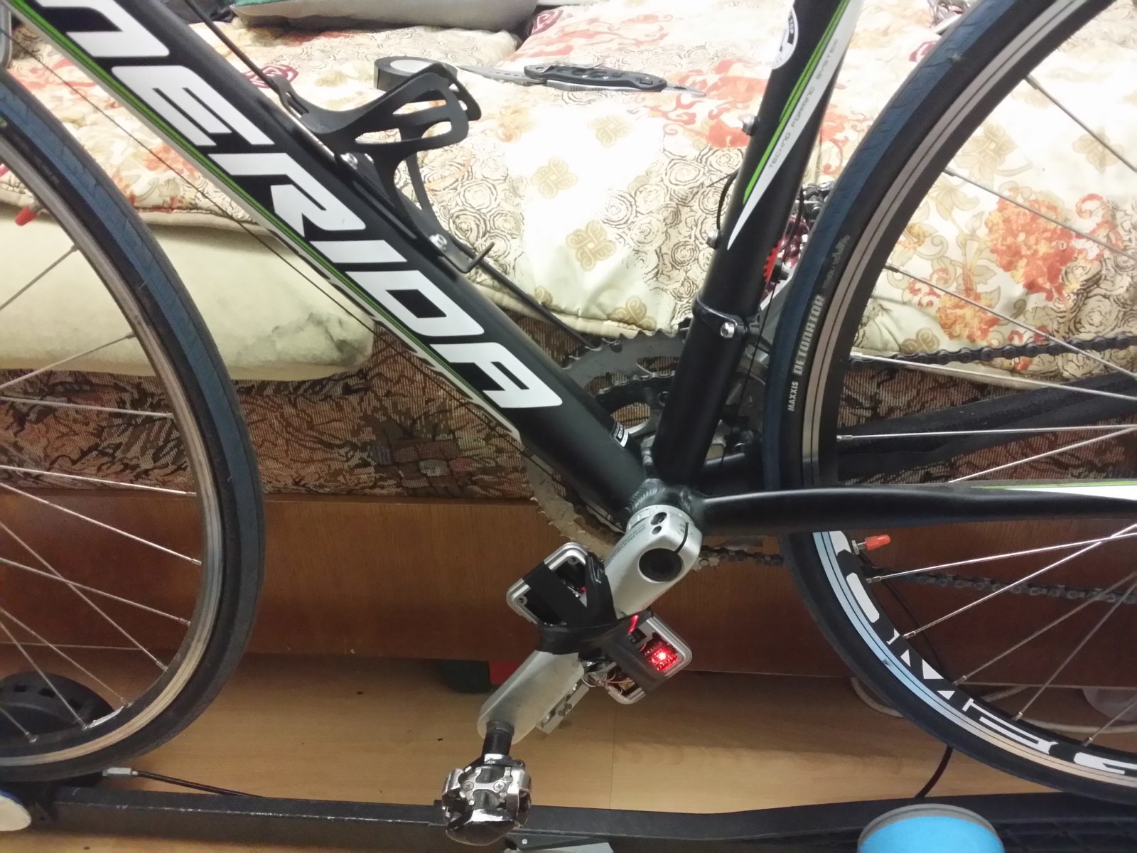
Everything was assembled and, surprisingly, the hardware worked the first time. I wound a block with microcircuits to the connecting rod with electrical tape, and the load sensor stuck it to the connecting rod with hot glue (as it turned out later, this is not a good idea, the sensor is so accurate that it measures the easiest movements, and the glue has fluidity, which caused a signal drift)

It turned out ugly, but does not interfere with the ride.
Calibration
The weight sensor module does not transmit grams or kilograms, but some parrots that need to be set in accordance with the load. This was done using simple tools.

Nanocalibrator.
The load data was immediately transferred to the computer, with the help of which I found the correspondence of the signal and the applied effort:

Nonlinearity of the signal arises due to the fact that the connecting rod not only bends under load, but also twists.
A simple utility was written that receives data via bluetooth and displays them on the screen in real time. Again, in an unpretentious style :)

And this is exactly the interface of the iPhone 7?
So what do we see on the interface?
The big numbers on the top are power, on one side (remember, we only have the sensor on the left connecting rod?), So for full power you need to multiply by 2. By the way, the power formula is: N = moment * angular velocity, it is considered in the program.
kad - cadence
kilos - pressure on the pedal, in kilograms
The graph shows how the pressure on the pedal was distributed over time, vertical bars indicate the moment the reed switch passes the magnet, it is necessary to measure the cadence.
The pie chart shows how the load was distributed within one pedaling circle - the red sector is the pressure on the pedal, the green sector, then when the pedal goes up, and we rely on it with our foot (parasitic load)
For everything together, including a soldering iron, the budget was $ 30.
Most likely, the prices of famous manufacturers are so high because of the lack of demand, in my opinion, for the whole world, the annual market of parameters is only about 100 thousand units for all manufacturers combined.
My device showed operability, removed from the bike and postponed until better times when I can separate the board normally to reduce its size and other interface issues :)
Thank you for your attention!
Code for Arduino
Code for the studio
And I decided to collect this ...
Why do I need a powerful meter?
This device measures the power that you apply to the pedals. Knowing the power helps a lot in training: you can track your progress over time, it allows you to accurately understand what effort you make when riding - and are you now driving so slowly because you have not slept well, or is the road really going uphill? And gives many other useful features.
Why make a powerful meter yourself, instead of buying?
1 - the price of existing samples is simply monstrous , the cheapest samples cost 600 American money (and on average about 1000), not including delivery, customs clearance and a head unit (a screen / computer that displays data, which will cost at least $ 100 )
2 - because I'm interested in designing something and watching how it works :)
So, let's start.
The principle of operation
There are many options to measure power, I chose one of them: measure the bend of the connecting rod from the pressure of the foot on the pedal.
Material base
I have been searching for a long time, what kind of sensitive element is available and can be used in such a device? Various options were considered - optical sensors, piezoelectric sensors, measuring the frequency of transmitted sound, but came to the conclusion that it would be easiest to use a bridge load sensor. Having started looking for where it can be purchased, I came to the disappointing conclusion that it was either expensive or ordered in China and waited from two weeks to two months. But climbing on one local bulletin board, I found a proposal for the sale of scales with an accuracy of 0.01 grams and not at all expensive. I was not yet sure that such a sensor was in the balance, but I ordered it anyway.
It was very
unfortunate to disassemble, although they are inexpensive. Having opened the scales, I loaded them with exactly what I was looking for, a bridge load sensor!
A short experiment was conducted, with the help of which I found out whether such a sensor can measure the bend of the connecting rod.
Really works!
Since in the balance all electronic components were under one “drop”, then the entire electronic body kit had to be searched and done by yourself.
The list of parts that I chose :
1 - the amplifier of the HX711 weight sensor - a bridge sensor is connected to it, the output is a certain value, already digitally, convenient for processing
2 - the cadence sensor - reed switch, - is needed to measure the speed of the pedals, so how easy it is to measure the applied force to the pedals is not enough to measure the power, you need to know the rotation speed
3 - transmitter, bluetooth module HC-05, to transfer data to a computer or phone
4 - Arduino nano controller - the brains of the device process the data received from the amplifier and erkona data is sent to the transmitter
5 - power supply - since all modules require 5V power, you need a power source and a converter, the source decided to take the battery compartment from the scales from which the load was removed and putting it
all together I got the following picture
Nda, and how to put everything on the pedal ?
I had to fit everything in the case from all the same weights, it barely worked out. I am far from wiring and etching boards, so I just soldered wires to the legs of the microcircuits. If you breed a separate board and install smd components on it, you will, of course, get much less.
Everything was assembled and, surprisingly, the hardware worked the first time. I wound a block with microcircuits to the connecting rod with electrical tape, and the load sensor stuck it to the connecting rod with hot glue (as it turned out later, this is not a good idea, the sensor is so accurate that it measures the easiest movements, and the glue has fluidity, which caused a signal drift)
It turned out ugly, but does not interfere with the ride.
Calibration
The weight sensor module does not transmit grams or kilograms, but some parrots that need to be set in accordance with the load. This was done using simple tools.
Nanocalibrator.
The load data was immediately transferred to the computer, with the help of which I found the correspondence of the signal and the applied effort:
Nonlinearity of the signal arises due to the fact that the connecting rod not only bends under load, but also twists.
A simple utility was written that receives data via bluetooth and displays them on the screen in real time. Again, in an unpretentious style :)
And this is exactly the interface of the iPhone 7?
So what do we see on the interface?
The big numbers on the top are power, on one side (remember, we only have the sensor on the left connecting rod?), So for full power you need to multiply by 2. By the way, the power formula is: N = moment * angular velocity, it is considered in the program.
kad - cadence
kilos - pressure on the pedal, in kilograms
The graph shows how the pressure on the pedal was distributed over time, vertical bars indicate the moment the reed switch passes the magnet, it is necessary to measure the cadence.
The pie chart shows how the load was distributed within one pedaling circle - the red sector is the pressure on the pedal, the green sector, then when the pedal goes up, and we rely on it with our foot (parasitic load)
For everything together, including a soldering iron, the budget was $ 30.
Most likely, the prices of famous manufacturers are so high because of the lack of demand, in my opinion, for the whole world, the annual market of parameters is only about 100 thousand units for all manufacturers combined.
My device showed operability, removed from the bike and postponed until better times when I can separate the board normally to reduce its size and other interface issues :)
Thank you for your attention!
Code for Arduino
Code for the studio