Arduino RGB Night Light
Probably everyone in childhood had a dream (and not one). You can even try to recall the feeling that overwhelms the soul of a child in fulfilling his dreams or that distant familiar gleam in his eyes ... As a child, I dreamed of having my nightlight.
Now I am studying in the 4th year of BSUIR and when we were informed that the course project on circuitry can be done not on paper but on a piece of iron, it dawned on me: the nightlight, which I so desired in childhood, can be done on my own. And to make not just an object that will illuminate the room in the dark, but a device that can be easily controlled to suit any mood. Why not? I decided to add the ability to change colors using my hands: the closer the hand is brought to the night light, the brighter one of the colors (RGB) lights up. And I would also like to control the nightlight using the remote control.
I admit right away that I spied the idea on cxem.net . In short, this example used an RGB matrix that was controlled using shift registers and ultrasonic distance sensors. But I thought that the matrix shines exclusively in one direction, but I wanted the nightlight to shine on both sides.
Substantiation of circuit elements
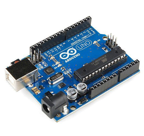 I turned my attention to the Arduino microcontrollers. UNO is quite a suitable option for my idea, firstly because it is the most popular platform and the number of pins is not too large, unlike Mega, and secondly, you can connect an external power source to it, in my case it is 12V, unlike Nano thirdly ... well, I think you can focus on these two points. The platform is very popular all over the world due to the convenience and simplicity of the programming language, as well as its open architecture and program code.
 More information about this board can be easily found on the Internet, so I will not overload the article.
So, the basic requirements for the system. Required:
- sensors that will track the distance to the barrier to control the system;
- a sensor for reading signals from the remote control;
- LEDs, which will provide the necessary lighting functionality;
- a control unit that will control the entire system.
Range sensors are required as distance sensors for the project, each of which will correspond to a specific color: red, green, blue. The distance sensors will monitor the distance of the hand to the night lamp and the closer the hand is brought to a specific sensor, the more the color corresponding to this range finder will burn. Conversely, the farther the hand, the less voltage is applied to the color corresponding to the sensor.
The most popular rangefinders at the moment are Sharp GP2Y0A21YK and HC-SR04. Sharp GP2Y0A21YK is an infrared rangefinder. It is equipped with an IR emitter and an IR receiver: the first serves as a source of the beam, the reflection of which catches the second. In this case, the infrared rays of the sensor for the human eye are invisible and harmless at such an intensity.
Compared to the HC-SR04 ultrasonic sensor, this sensor has both advantages and disadvantages. The advantages include neutrality and harmlessness. And the disadvantages are a shorter range and dependence on external noise, including some types of lighting.
 The ultrasonic range finders HC-SR04 were used as distance sensors for the project.
The principle of action of HC-SR04 is based on the well-known phenomenon of echolocation. When using it, the emitter generates an acoustic signal, which, reflected from the obstacle, returns to the sensor and is recorded by the receiver. Knowing the speed of ultrasound propagation in air (approximately 340 m / s) and the delay time between the emitted and received signal, it is easy to calculate the distance to the acoustic barrier.
The TRIG input is connected to any pin of the microcontroller. A pulse digital signal of 10 μs duration must be supplied to this output. The signal at the input TRIG sensor sends a pack of ultrasonic pulses. After receiving the reflected signal, the sensor generates a pulse signal at the ECHO output, the duration of which is proportional to the distance to the obstacle.
 IR sensor. Of course, the signal necessary for remote control will be read and decoded from this sensor. TSOP18 differ only in frequency. Sensor VS1838B TSOP1838 was selected for the project.
 The project was based on the idea of lighting the room in any color, this suggests that 3 primary colors will be needed from which lighting will be obtained: red, green, blue. Therefore, the SMD 5050RGB LED model was chosen, which will perfectly cope with the task.
Depending on the amount of voltage supplied to each LED, they will change the intensity of this lighting. The LED must be connected through a resistor, otherwise we risk spoiling not only it, but also Arduino. A resistor is needed in order to limit the current on the LED to an acceptable value. The fact is that the internal resistance of the LED is very low and, if you do not use a resistor, a current will pass through the LED that simply burns both the LED and the controller.
 The strips with LEDs that are used in the project are powered by 12V.
 Due to the fact that the voltage on the LEDs in the “off” state is 6V and it is necessary to regulate the power supply that exceeds 5V, it is necessary to add transistors to the circuit in the key mode. My choice fell on the model BC547c.
Consider briefly, for those who have forgotten, the principle of operation of the npn transistor. If you do not apply voltage at all, but simply take and close the conclusions of the base and emitter, even if not short, but through a resistor of several ohms, it turns out that the base-emitter voltage is zero. Consequently, there is no base current. The transistor is closed, the collector current is negligible, just the same initial current. In this case, they say that the transistor is in a cutoff state. The opposite state is called saturation: when the transistor is fully open, so that there is nowhere to open further. With such a degree of opening, the resistance of the collector-emitter section is so small that it is simply impossible to turn on the transistor without load in the collector circuit, it will burn instantly. In this case, the residual voltage at the collector can be only 0.3 ... 0.5V.
These two states — saturation and cutoff — are used when the transistor is in key mode like a normal relay contact. The main point of this mode is that a small base current controls a large collector current, which is several tens of times greater than the base current. A large collector current is obtained due to an external energy source, but still the current gain, as they say, is obvious. In our case, the microcircuit, whose operating voltage is 5V, includes 3 strips with LEDs operating from 12V.
We calculate the operation mode of the key cascade. It is required to calculate the value of the resistor in the base circuit so that the LEDs burn at full power. A necessary condition in the calculation is that the current gain is greater than or equal to the quotient of dividing the maximum possible collector current by the minimum possible base current:

Therefore, the strips can be 220 V operating voltage, and the base circuit can be controlled from a 5 V microcircuit. If the transistor is designed to work with such a voltage on the collector, then the LEDs will light up without problems.
The voltage drop at the base-emitter junction is 0.77V, provided that the base current is 5mA and the collector current is 0.1A.
The voltage at the base resistor will be:
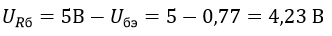
According to Ohm's Law:
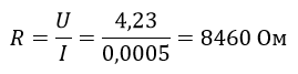
From the standard series of resistances, we choose a 8.2 kOhm resistor. The calculation is now complete.
I want to draw your attention to one problem that I encountered. When using the IRremote library, the Arduino crashed while adjusting the blue color. After a long and thorough search on the Internet, it turned out that this library uses the default timer 2 for this Arduino model. Timers are used to control PWM outputs.
Timer 0 (System time, PWM 5 and 6);
Timer 1 (PWM 9 and 10);
Timer 2 (PWM 3 and 11).
Initially, I used PWM 11 to adjust the blue color. Therefore, be careful when working with PWM, timers and third-party libraries that can use them. It is strange that nothing was said about this nuance on the main page on the github. If you wish, you can uncomment the line with timer 1 and comment 2.
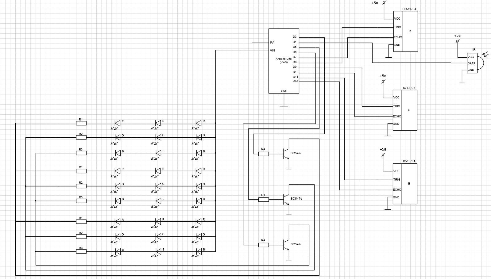
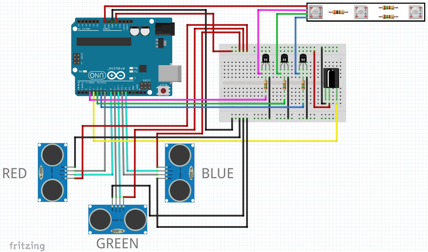
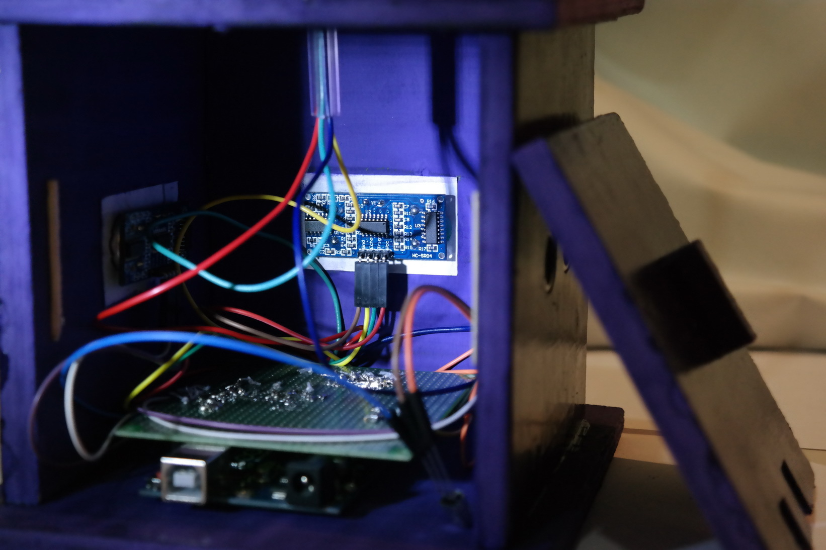
Connecting elements on the breadboard looks like this:
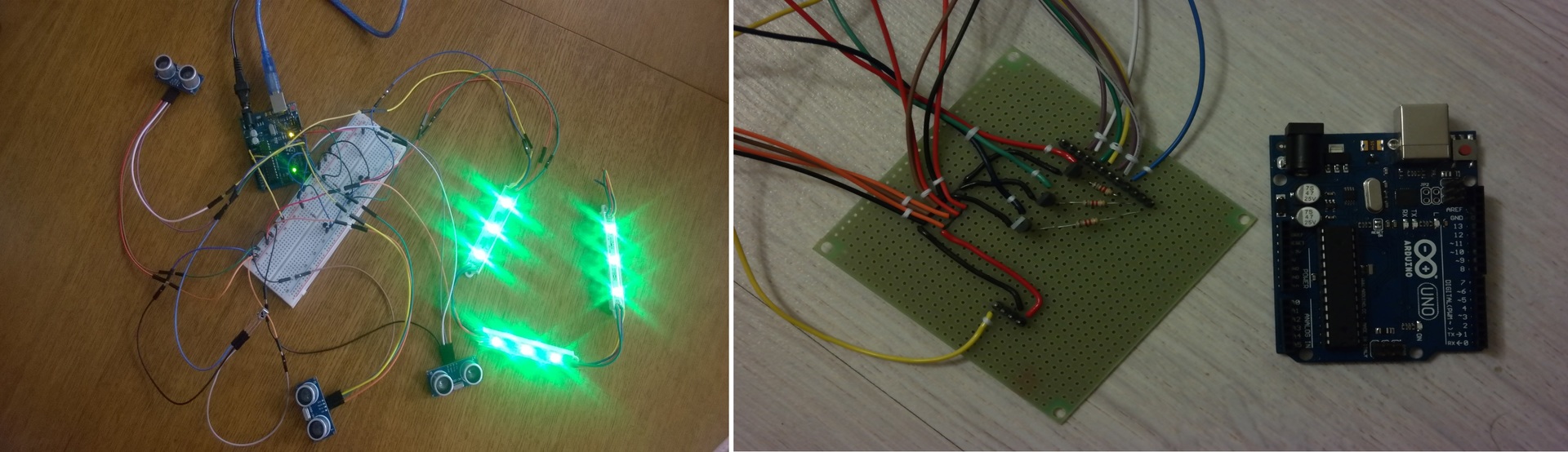
After testing on the breadboard, the phases “Placement of elements on the board” and “Work with a soldering iron” began. After the first test of the finished board, a thought creeps into my head: something went wrong. And then the familiar phase of “Painstaking work with the tester” begins. However, the malfunctions (several neighboring contacts were accidentally soldered) were quickly fixed and here he is the long-awaited mischievous light of LEDs.
Further, it was only the case. For this reason, plywood with holes for our sensors was cut. The back cover was made specially removable so that you can enjoy the view from the inside and, if desired, to finish or remake something. It also has 2 holes for reprogramming the board and power.
The body was glued on a two-component epoxy adhesive. It is worth noting the peculiarity of this glue, for those who have not met with it before. This companion is delivered in two separate containers, when the contents of which are mixed, an instant chemical reaction occurs. After mixing, you have to act quickly, within 3-4 minutes. For further use, you need to mix a new portion. So if you are trying to repeat this, my advice to you is to mix in small portions and act very quickly, there will not be much time to think. Therefore, it is worth considering in advance how and where to glue the case. And in one sitting this will not work.
To fix the strips with LEDs, a tube was inserted into the top cover through which all the wires went perfectly.

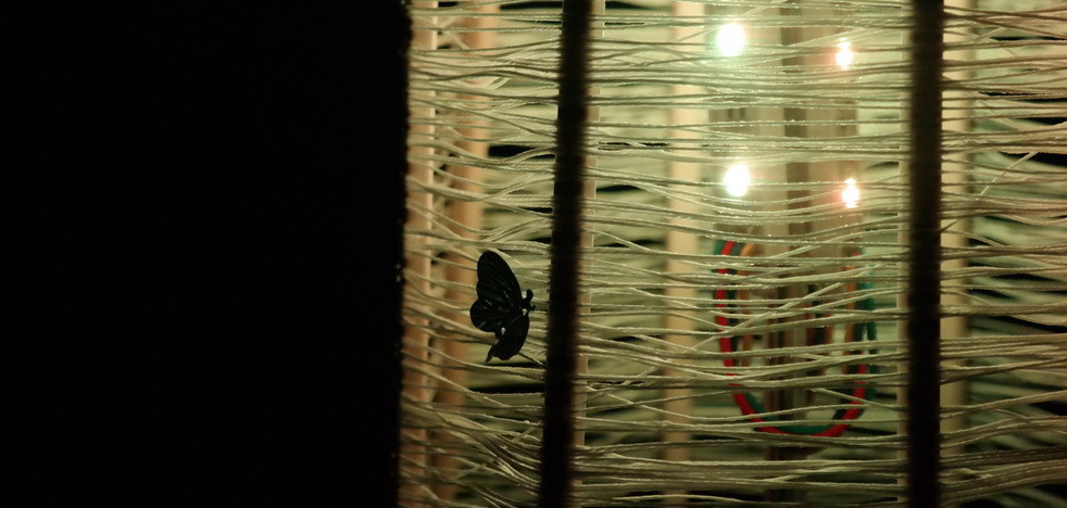
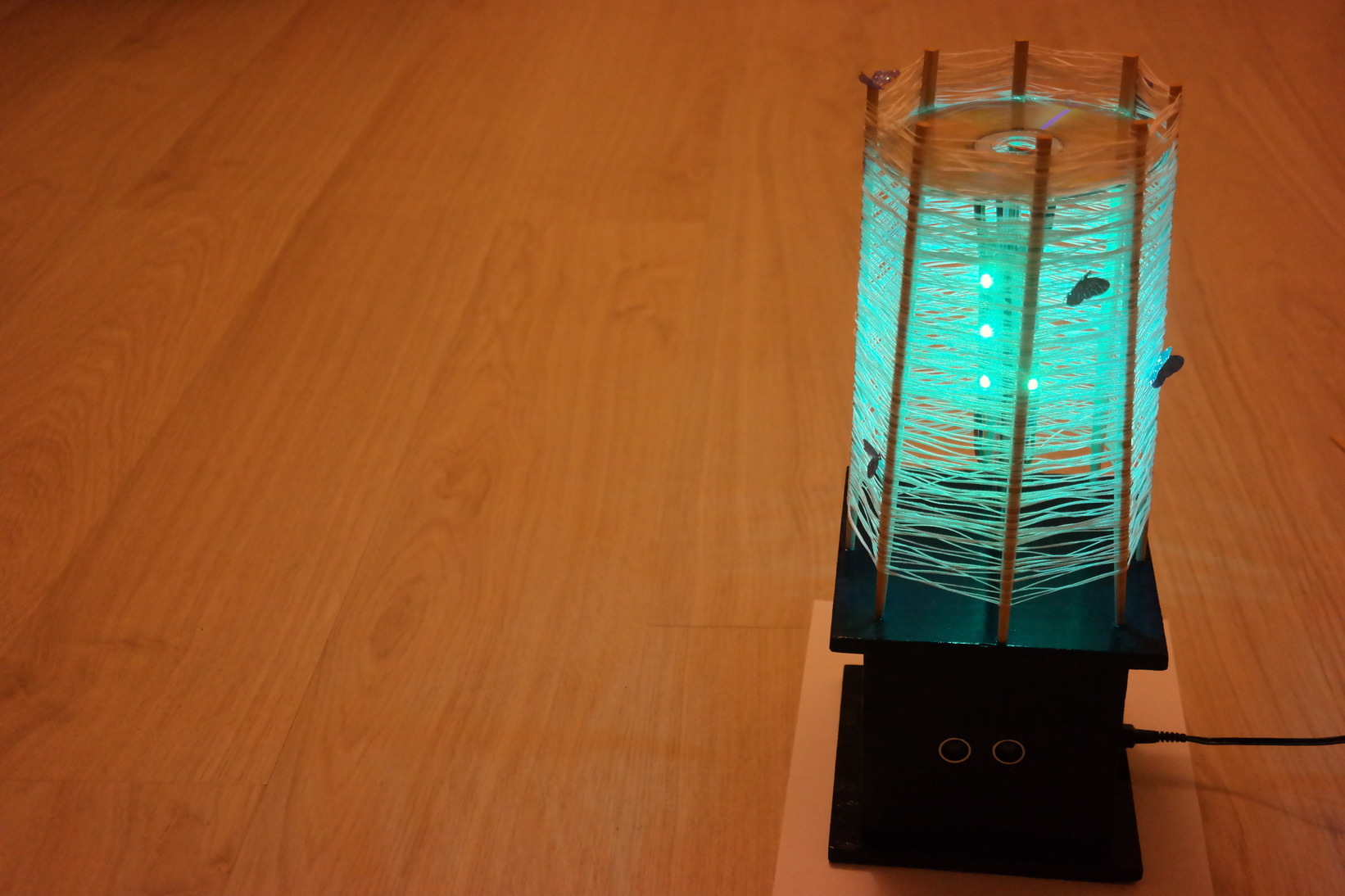
When the question arose with a lampshade, I remembered how in childhood I made crafts from simple thread, glue and a balloon, which served as the basis. The principle for the lampshade is the same, but wrapping a polyhedron was more difficult than a ball. Due to the pressure exerted by the threads on the structure, it began to taper upward and the threads began to fall. Emergency, with hands in glue, it was decided to strengthen the structure from above. And then the CD came to the rescue. As a result, we got such a nightlight:
What do you want to say as a result
What should I change in the project? To signal TRIG distance sensors, one Arduino output could be used instead of three. I would also have provided a hole for the infrared sensor (which I forgot about), which, alas, is hidden in the housing from which, of course, it naturally cannot read signals from the remote control. However, who said that you can’t solder and drill anything?
I would like to note that this was an interesting semester, and a great opportunity to try to do something not on paper, so I can put another checkmark next to the item “childhood dream”. And if it seems to you that trying something new is difficult, and you don’t know what to do first, don’t worry. The thought flies through the mind of many: where to start here and how can this be done at all? There are many tasks in life that you can get confused about, but if you just try, you will notice that with a twinkle in your eyes you can turn mountains, even if you have to try a little for that.
Link to the source code .
Article author: Anastasia Kovsh