Impulse counter on Linux (we obtain information on gas flow from a VK-G4 counter)
In the process of household automation, it was discovered that the VK-G4 gas flow meter available has an interesting feature: a magnet is built into the junior discharge, which can close the reed switch installed outside the device itself (i.e., permission is not required to connect it gas company). This is even indicated in the passport on the counter itself. True, it is recommended that you use the “IN-Z 61 low-frequency pulse generator,” but in reality it’s just a reed switch mounted on a meter for an insane price. Therefore, instead of IN-Z 61, it was decided to use the cheapest Hall sensor with a digital output (i.e. with an integrated Schmitt trigger).
From the available was taken Hall sensor type SS441A. According to datasheeton SS44xA in the third digit its magnetic sensitivity is encoded, which determines the physical location of the sensor on the gas meter.
As a control system, I use a single-board Banana PI computer running Linux (vanilla kernel 4.2+). The physical connection of the SS44xA is very simple: we
connect the output (-) to a common wire;
the output (+) is connected to + 5V (and not to + 3.3V);
pin (D) is connected to the GPIO port and pulled through a 4.7 kΩ resistor to + 3.3V.
But what was my surprise when I could not find kernel in-tree drivers that could just count the number of pulses on a given GPIO port! I understand that Linux is not a real-time OS, but just counting low-frequency pulses ... Has it really been my job?
Having carefully looked at the latest kernel sources, two intermediate solutions were discovered:
Using any of these solutions will require a daemon application that must be active to perform pulse counting. This is not the best solution, because if it is completed for any reason, we can skip a certain number of pulses, which is quite critical for accounting purposes. Therefore, to minimize the risks, it was decided to write our own device driver that would work directly at the kernel level.
So, meet: a driver for counting pulses on an arbitrary GPIO line , configurable using Device Tree technology.
Preconditions
For my work, I use the assembly from Armbian , and on their website you can also take the kernel sources, on the basis of which the assembly was prepared. But, in principle, there should be no restrictions on the target assembly.
I don’t describe the assembly of the external module (and what? In principle, there are a lot of resources with such a description), so we believe that you already have ready-made counters.ko gpio-pulse.ko modules assembled for your core. I describe the further process using the example of Banana PI, but by analogy it can be transferred to any other platform.
Open the connector description plateon the board. We are interested in the CON3 connector (GPIO Headers). We select any contact we like and determine its functionality (for example, I liked pin 12 on the CON3 connector, to which the PH2 socket port is connected). We check with Allwinner A20 datasheet (GPIO multiplexing function table) - the selected port should support the generation of interrupts (in my case it is EINT2 in the Multi 6 column). Next, we need to determine the pin number in terms of GPIO, which corresponds to the selected port (PH2). It was easier for me to determine this directly on the working device:
# grep '(PH2)' /sys/kernel/debug/pinctrl/1c20800.pinctrl/pinmux-pins
pin 226 (PH2): (MUX UNCLAIMED) (GPIO UNCLAIMED)
at the same time and made sure that this port is currently not being used by anything (MUX and GPIO UNCLAIMED).
Now you can create a Device Tree configuration. Examples for some devices are in the source code of the Linux kernel in the arch / arm / boot / dts folder, for Banana the PI file is called sun7i-a20-bananapi.dts
In it we make the following changes:
The gpios parameter in node is calculated as follows:
The interrupts parameter in node is calculated as follows:
We compile the modified Device Tree file:
With the resulting sun7i-a20-bananapi.dtb, we overwrite the file in /boot/dtb/sun7i-a20-bananapi.dtb We write the
kernel modules counters.ko gpio-pulse.ko anywhere in / lib / modules / $ (uname -r) / kernel / drivers and load the target system. On the loaded target system, we give the command
and reboot again. After that, we look at the output of the dmesg command:
Great, the modules are loaded and functional. We check the functionality first programmatically:
(we simulated a signal by software).
Now we connect the Hall sensor and make sure of its operability by bringing some magnet to it (for example, from a magnetic sticker on the refrigerator).
Finally, I had time to post pictures. So:
Actually the sensor. Its sensitive part is the side without bevels (that is, we press it to the meter under the least discharge).
Then we fix the sensor with electrical tape.
For strength, cut a piece of foam into the gas meter for the size of the recess and then fix the sensor to it.

Then we fix this piece and the wire with electrical tape.
Well and this is what happened as a result.
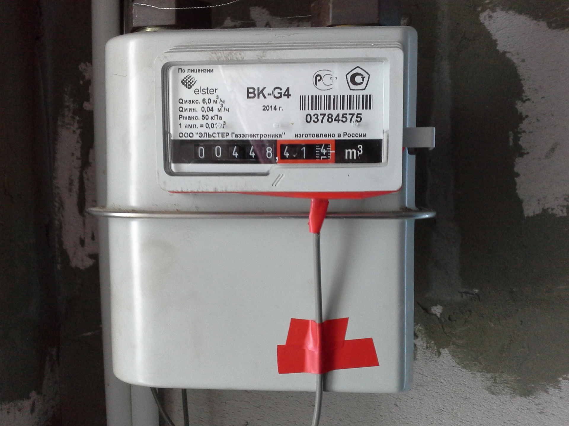
For the decision on fasteners, please do not kick your feet, because the house is still undergoing repairs and fixtures, in fact, is a prototype.
From the available was taken Hall sensor type SS441A. According to datasheeton SS44xA in the third digit its magnetic sensitivity is encoded, which determines the physical location of the sensor on the gas meter.
As a control system, I use a single-board Banana PI computer running Linux (vanilla kernel 4.2+). The physical connection of the SS44xA is very simple: we
connect the output (-) to a common wire;
the output (+) is connected to + 5V (and not to + 3.3V);
pin (D) is connected to the GPIO port and pulled through a 4.7 kΩ resistor to + 3.3V.
But what was my surprise when I could not find kernel in-tree drivers that could just count the number of pulses on a given GPIO port! I understand that Linux is not a real-time OS, but just counting low-frequency pulses ... Has it really been my job?
Having carefully looked at the latest kernel sources, two intermediate solutions were discovered:
- Use a standard UIO driver. If such a device is opened as a file in the application program and the corresponding value is written to it, the subsequent read operation from it will be suspended until an interruption occurs due to a change in the signal level on the corresponding GPIO;
- Use the standard gpio_keys driver. Using it, you can declare the GPIO as a “button” or “switch” and catch events related to changes in their state in the application program.
Using any of these solutions will require a daemon application that must be active to perform pulse counting. This is not the best solution, because if it is completed for any reason, we can skip a certain number of pulses, which is quite critical for accounting purposes. Therefore, to minimize the risks, it was decided to write our own device driver that would work directly at the kernel level.
So, meet: a driver for counting pulses on an arbitrary GPIO line , configurable using Device Tree technology.
Preconditions
- Used Linux kernel version 4.x or later
- Kernel header files used to build it (usually located in / usr / include / linux on the target system)
- Tools for compiling modules on the target system or tools for cross-compiling
- Source or binary Device Tree for your hardware platform
- Compiler Device Tree to binary format (dtc program)
For my work, I use the assembly from Armbian , and on their website you can also take the kernel sources, on the basis of which the assembly was prepared. But, in principle, there should be no restrictions on the target assembly.
I don’t describe the assembly of the external module (and what? In principle, there are a lot of resources with such a description), so we believe that you already have ready-made counters.ko gpio-pulse.ko modules assembled for your core. I describe the further process using the example of Banana PI, but by analogy it can be transferred to any other platform.
Open the connector description plateon the board. We are interested in the CON3 connector (GPIO Headers). We select any contact we like and determine its functionality (for example, I liked pin 12 on the CON3 connector, to which the PH2 socket port is connected). We check with Allwinner A20 datasheet (GPIO multiplexing function table) - the selected port should support the generation of interrupts (in my case it is EINT2 in the Multi 6 column). Next, we need to determine the pin number in terms of GPIO, which corresponds to the selected port (PH2). It was easier for me to determine this directly on the working device:
# grep '(PH2)' /sys/kernel/debug/pinctrl/1c20800.pinctrl/pinmux-pins
pin 226 (PH2): (MUX UNCLAIMED) (GPIO UNCLAIMED)
at the same time and made sure that this port is currently not being used by anything (MUX and GPIO UNCLAIMED).
Now you can create a Device Tree configuration. Examples for some devices are in the source code of the Linux kernel in the arch / arm / boot / dts folder, for Banana the PI file is called sun7i-a20-bananapi.dts
In it we make the following changes:
/ {
        model = "Banana Pi BPI-M1";
        compatible = "sinovoip,bpi-m1", "allwinner,sun7i-a20";
...
        counters {
                compatible = "gpio-pulse-counter";
                gas-meter@0 {
                    label = "Gas meter";
                    pinctrl-names = "default";
                    pinctrl-0 = <&ext_counter_bananapi>;
                    /* CON3, pin 12: PH2 - pin 226 (Multi6 function: EINT2) */
                    /* bank: 226 / 32 = 7, pin into the bank 226 % 32 = 2 */
                    gpios = <&pio 7 2 GPIO_ACTIVE_LOW>;
                    interrupt-parent = <&pio>;
                    interrupt-names = "counter-edge-falling";
                    interrupts = <2 IRQ_TYPE_EDGE_FALLING>; /* PH2 / EINT2 */
                };
        };
&pio {
        ...
        /* External counter */
        ext_counter_bananapi: counter_pins@0 {
                allwinner,pins = "PH2";
                allwinner,function = "gpio_in";
                allwinner,drive = ;
                allwinner,pull = ;
        };
};
The gpios parameter in node is calculated as follows:
- First comes a link to the pio label;
- Next is the bank number, which contains the desired GPIO port. For Allwinner A20, each bank contains 32 ports, so the bank number is defined as the integer part of dividing the GPIO pin by 32;
- Next is the pin number inside the bank. Because each bank has 32 pin, then this value is calculated as the remainder of dividing the GPIO pin by 32;
- The last parameter is an indication of which signal level is considered active
The interrupts parameter in node is calculated as follows:
- The first parameter indicates the interrupt number of the GPIO controller (for EINT2 it will be 2)
- The second parameter is IRQ_TYPE_EDGE_FALLING, which allows the generation of an interrupt when the signal goes from high to low (because we have an open collector sensor and pulled to + VCC)
We compile the modified Device Tree file:
dtc -I dts -O dtb sun7i-a20-bananapi.dts > sun7i-a20-bananapi.dtb
With the resulting sun7i-a20-bananapi.dtb, we overwrite the file in /boot/dtb/sun7i-a20-bananapi.dtb We write the
kernel modules counters.ko gpio-pulse.ko anywhere in / lib / modules / $ (uname -r) / kernel / drivers and load the target system. On the loaded target system, we give the command
depmod -a
and reboot again. After that, we look at the output of the dmesg command:
# dmesg
...
[    4.745570] counters: Class driver loaded.
[    4.749235] gpio_pulse: Device #0 gas-meter: IRQ: 53 GPIO: 226
...
Great, the modules are loaded and functional. We check the functionality first programmatically:
# cat /sys/class/counters/counter0/values/count
0
# echo 1 > /sys/class/counters/counter0/values/pulse
# cat /sys/class/counters/counter0/values/count
1
# echo 1 > /sys/class/counters/counter0/values/pulse
# echo 1 > /sys/class/counters/counter0/values/pulse
# cat /sys/class/counters/counter0/values/count
3
(we simulated a signal by software).
Now we connect the Hall sensor and make sure of its operability by bringing some magnet to it (for example, from a magnetic sticker on the refrigerator).
Afterword
Finally, I had time to post pictures. So:
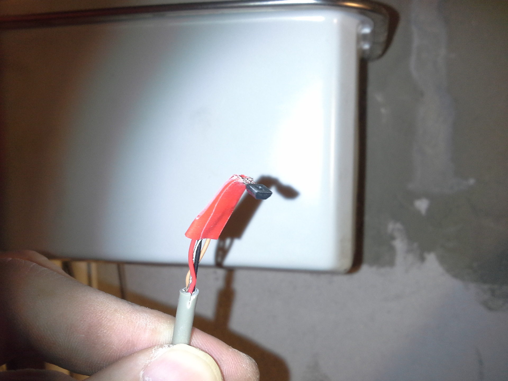
Actually the sensor. Its sensitive part is the side without bevels (that is, we press it to the meter under the least discharge).
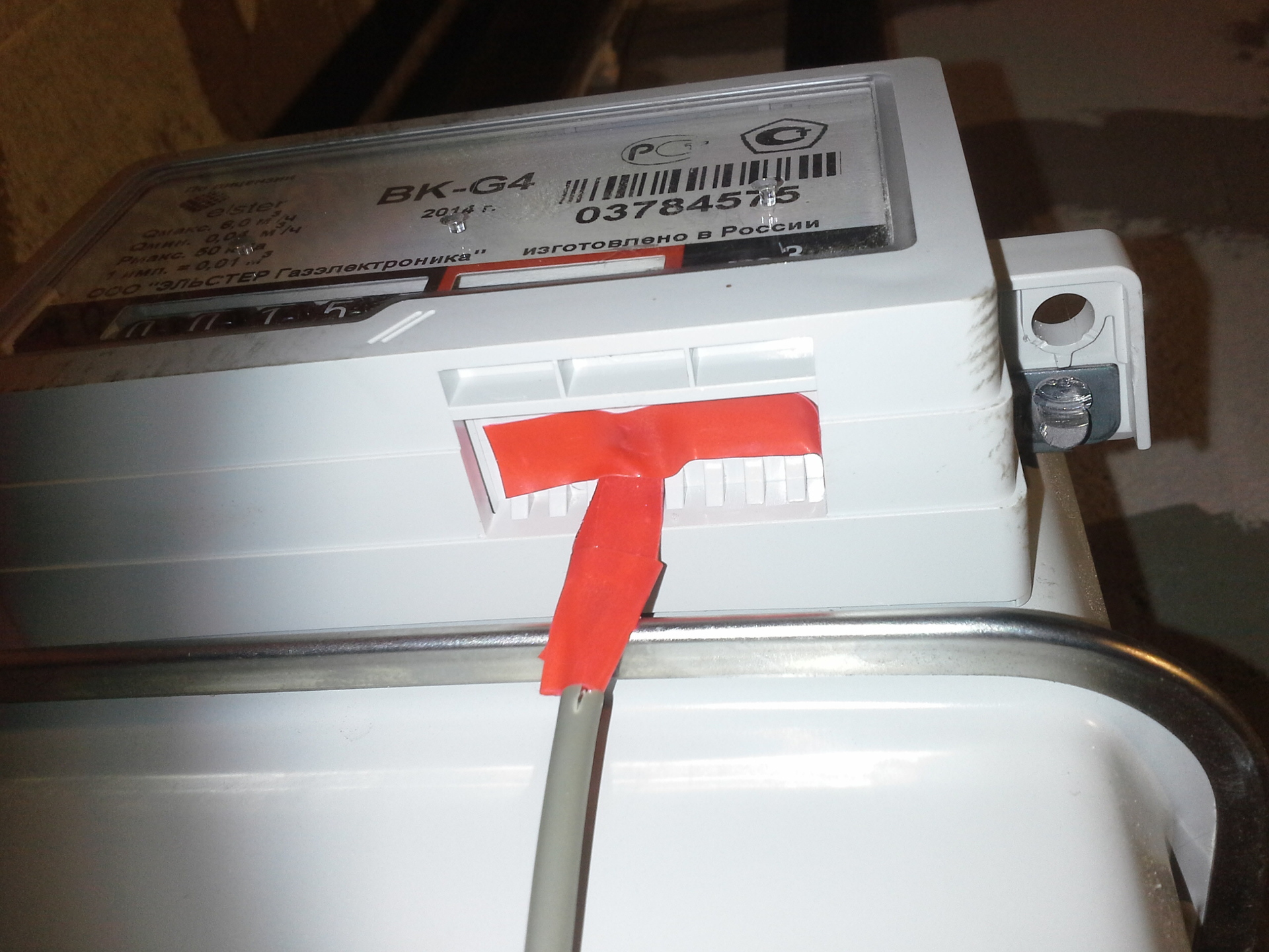
Then we fix the sensor with electrical tape.
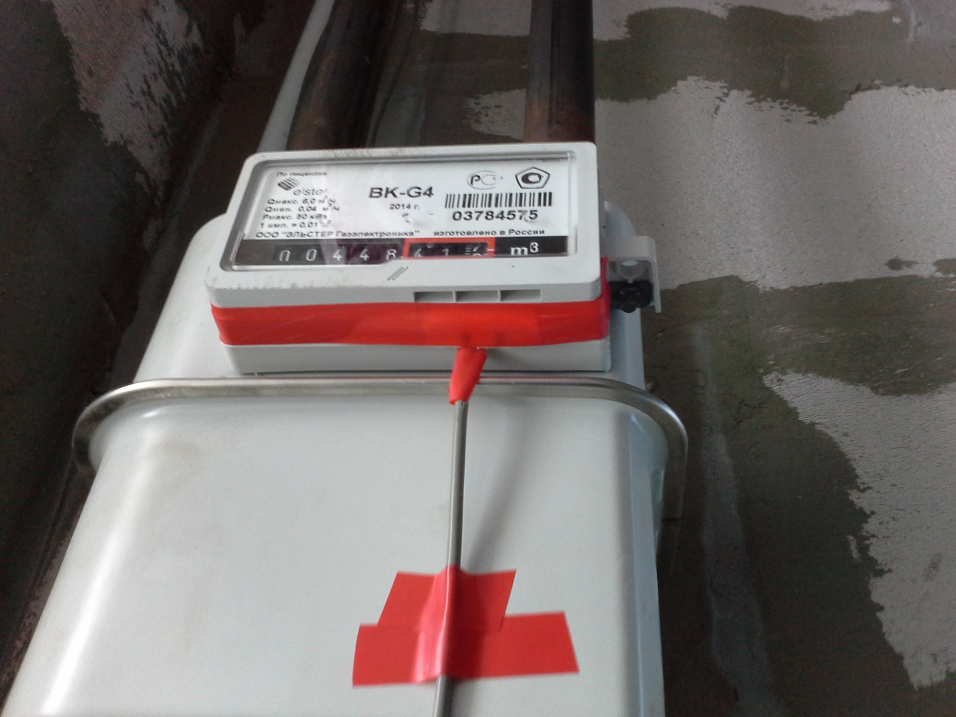
For strength, cut a piece of foam into the gas meter for the size of the recess and then fix the sensor to it.
Then we fix this piece and the wire with electrical tape.
Well and this is what happened as a result.
For the decision on fasteners, please do not kick your feet, because the house is still undergoing repairs and fixtures, in fact, is a prototype.