CR2450 Wireless Lighting-Sensor
To make some kind of wireless sensor containing a barometer, thermometer, hygrometer or all in one bottle, powered by 220V is not a problem. But to power such a device from batteries or accumulators is already more interesting. Well, if it is a disc lithium battery (tablet) - it's generally cool, because the device will turn out to be very compact. 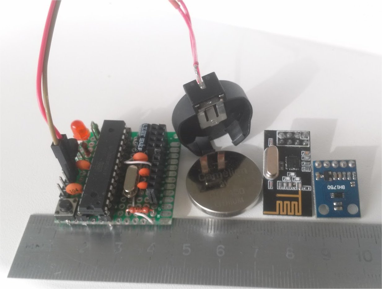
The only obstacle to using the “pill” is its small capacity. But even among the "tablets" there are quite suitable specimens, for example CR2450, with the claimed capacity of 550-610 mAh.
Since at the time of manufacturing the device I already had ready-made indoor and outdoor temperature and humidity sensors, I decided to make a Lighting-sensor based on the BH1750 and place it on the balcony, additionally equipping it with a DS18B20 temperature sensor.
Since I have all the windows facing south, the outdoor temperature and humidity sensor is significantly affected by sunlight, this effect has to be compensated for by weather data received from the Internet, in the future, I plan to use information about the level of lighting to calculate compensation.
To minimize the energy consumed by the sensor, it was decided:
1. To abandon the use of the finished Arduinki and use the ATmega 328P-PU microcontroller directly with 8 MHz quartz. I refused to use the internal RC generator, because due to significant changes in external temperature, the operating frequency is not stable.
2. Use the LowPower library and enable the LowPower.powerDown power saving mode (SLEEP_8S, ADC_OFF, BOD_OFF) for the controller
3. Power the DS18B20 sensor from the digital output of the microcontroller and turn it on immediately before measurement.
4. Power the radio module and BH1750 directly, using the energy saving modes, radio.powerDown () and Light.configure (BH1750_ONE_TIME_HIGH_RES_MODE), respectively.
Armed with the USBasp programmer, I
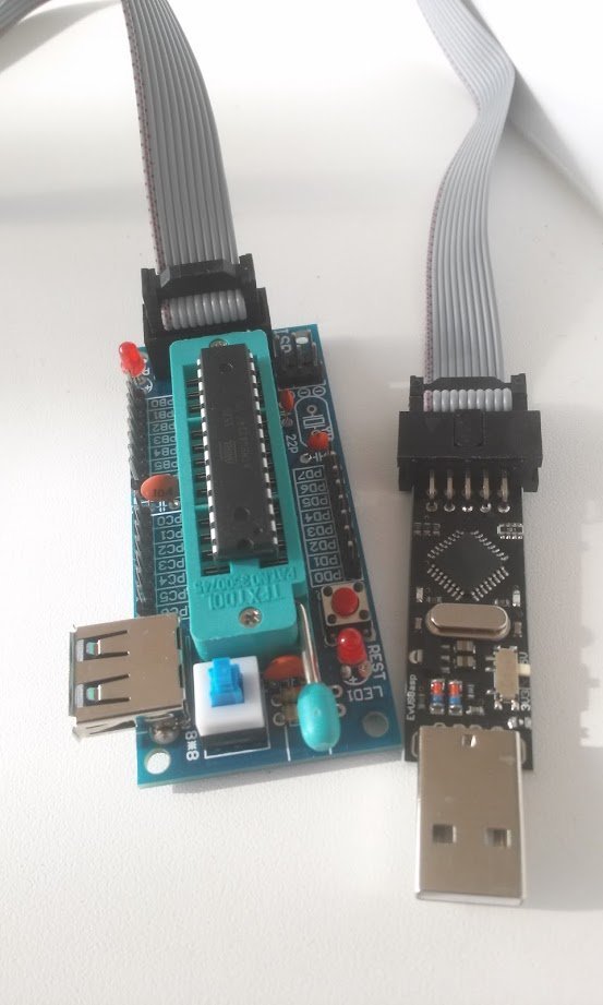
asked the fusion controller to the controller and, of course, the bootloader. I assembled a prototype, sketched a test sketch and measured the consumed currents: in sleep mode it turned out 14 μA, in the mode of taking readings from sensors - 3-4 mA, in the mode of data transmission via nRF24 to a weather station - 16-18 mA. Given the fact that I decided to take readings from the sensors once every 3 minutes, and transmit every 10 minutes - the sensor is very economical.
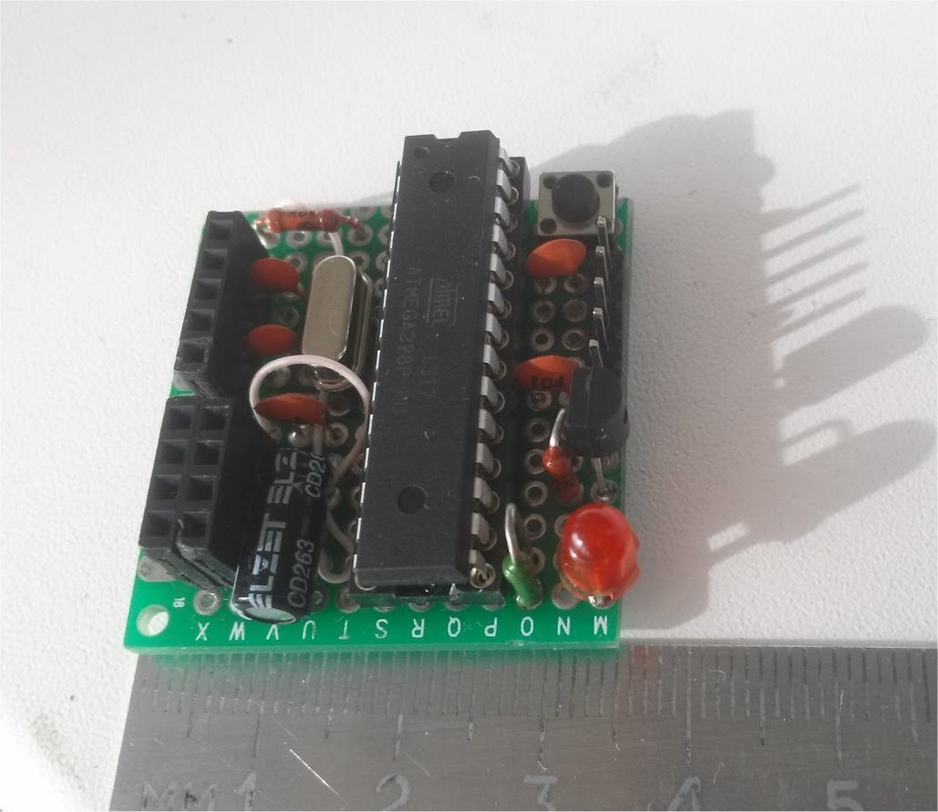
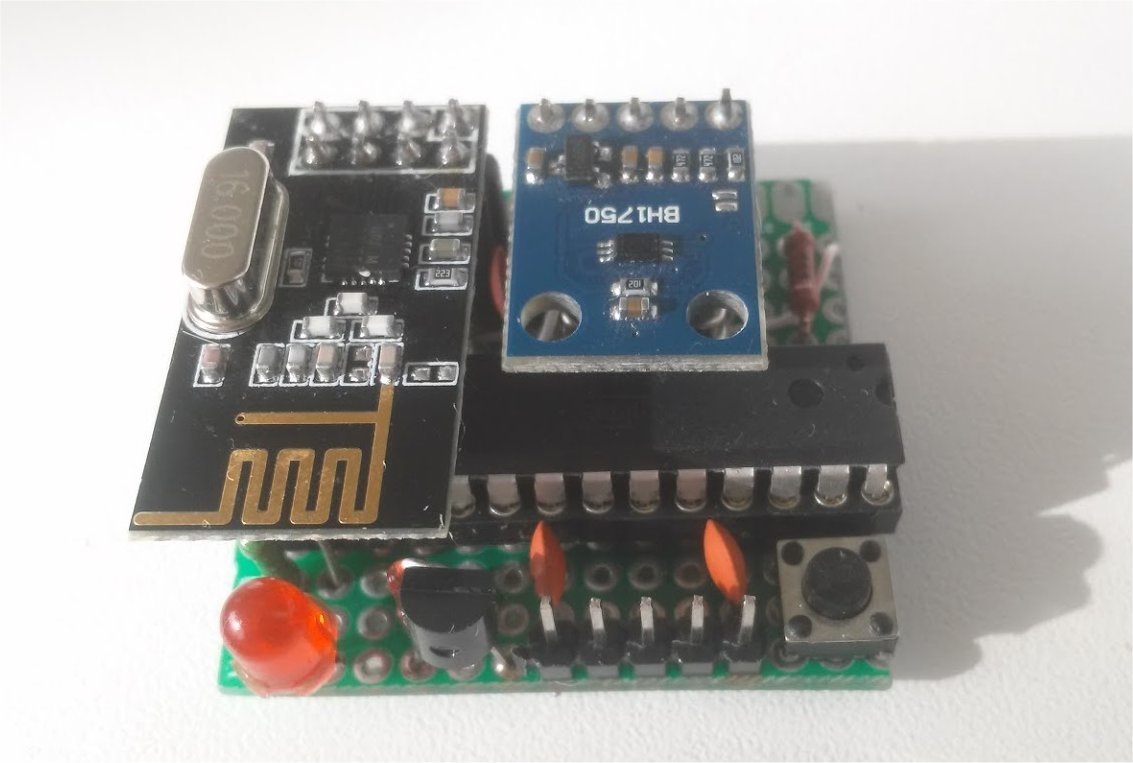
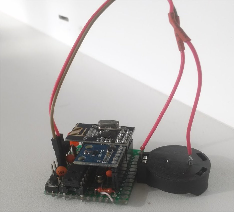
For the manufacture of the final device used a piece of breadboard and wire MGTF. The result is what happened:
To monitor the battery status, we use the built-in features of ATmega, which are well described in this article .
The process of flashing the bootloader and fuses is covered in detail here and here .
The general idea of creating an autonomous sensor was borrowed on the maniacbug website .
The sensor has already been lying (and working) for the second month on the balcony on the windowsill, sends data correctly. The power control reports that during this time the voltage of the source decreased from 3.05V when first turned on to 2.98V. However, during the day, when the sun warms up the balcony, the voltage can rise up to 3.00V. I look forward to cold weather, let's see how the selected battery will show itself at low temperatures.
With the selected duration of sleep mode, it turns out that the sensor is awake only 492-495 seconds in 24 hours.
The device is complete, but unfortunately so far without a case, I can not find a suitable

The only obstacle to using the “pill” is its small capacity. But even among the "tablets" there are quite suitable specimens, for example CR2450, with the claimed capacity of 550-610 mAh.
Since at the time of manufacturing the device I already had ready-made indoor and outdoor temperature and humidity sensors, I decided to make a Lighting-sensor based on the BH1750 and place it on the balcony, additionally equipping it with a DS18B20 temperature sensor.
Since I have all the windows facing south, the outdoor temperature and humidity sensor is significantly affected by sunlight, this effect has to be compensated for by weather data received from the Internet, in the future, I plan to use information about the level of lighting to calculate compensation.
To minimize the energy consumed by the sensor, it was decided:
1. To abandon the use of the finished Arduinki and use the ATmega 328P-PU microcontroller directly with 8 MHz quartz. I refused to use the internal RC generator, because due to significant changes in external temperature, the operating frequency is not stable.
2. Use the LowPower library and enable the LowPower.powerDown power saving mode (SLEEP_8S, ADC_OFF, BOD_OFF) for the controller
3. Power the DS18B20 sensor from the digital output of the microcontroller and turn it on immediately before measurement.
4. Power the radio module and BH1750 directly, using the energy saving modes, radio.powerDown () and Light.configure (BH1750_ONE_TIME_HIGH_RES_MODE), respectively.
Armed with the USBasp programmer, I

asked the fusion controller to the controller and, of course, the bootloader. I assembled a prototype, sketched a test sketch and measured the consumed currents: in sleep mode it turned out 14 μA, in the mode of taking readings from sensors - 3-4 mA, in the mode of data transmission via nRF24 to a weather station - 16-18 mA. Given the fact that I decided to take readings from the sensors once every 3 minutes, and transmit every 10 minutes - the sensor is very economical.
For the manufacture of the final device used a piece of breadboard and wire MGTF. The result is what happened:

To monitor the battery status, we use the built-in features of ATmega, which are well described in this article .
The process of flashing the bootloader and fuses is covered in detail here and here .
The general idea of creating an autonomous sensor was borrowed on the maniacbug website .
The sensor has already been lying (and working) for the second month on the balcony on the windowsill, sends data correctly. The power control reports that during this time the voltage of the source decreased from 3.05V when first turned on to 2.98V. However, during the day, when the sun warms up the balcony, the voltage can rise up to 3.00V. I look forward to cold weather, let's see how the selected battery will show itself at low temperatures.
With the selected duration of sleep mode, it turns out that the sensor is awake only 492-495 seconds in 24 hours.
The device is complete, but unfortunately so far without a case, I can not find a suitable


addition of 03/20/2016.
After 6 months, the device is still running on the original battery. The temperature on the balcony in January dropped to -24, while the voltage dropped to 2.5280V.
Now the battery (still quite lively) has been disconnected and powered from a 4F ionistro + a solar panel.
Now the battery (still quite lively) has been disconnected and powered from a 4F ionistro + a solar panel.
Source
#include
#include
#include
#include
#include
#include
#include
#include
/////// Сlass AVG //////////////////////////////////////////////////////////
class AVG {
  #define DEPTH_AVG 10
  private :
     int depth;
     long *mas;
     int cur;
     boolean first;
  public :
     boolean fDebug;
  AVG(int d)
  {
    if( d == 0 || d > DEPTH_AVG)depth = DEPTH_AVG;
    else depth = d;
    mas = (long *)malloc(sizeof(long)*depth);
    first = true;
    cur   = 0;
    fDebug = false;
  }
  void Set(long x)
  {
    if( first )
    {
       for( int i=0; i= depth ) cur = 0;
    }
    first = false;
  }
  long Get()
  {
    long x=0;
    for( int i=0; i 0 || ll > 0 || T < tt-2 || T > tt+2 || V < vv-100/*0.1V*/)
  { // уменьшим кол-во передач в темное время
    tAVG.Set(T);
    lAVG.Set(L);
    vAVG.Set(V);
    allowSend = true;     //Есть что отправить - Взведем флаг
    // Если освещенность изменилась с 0 (рассвет)
    if (ll == 0 &&  L > 0)
      lAVG.Set(L);
  }
  ReadCount++;
  /////////////////////////////////////////////////////////////
  if (DEBUG_MODE)
  {
    Serial.print("T= ");
    Serial.print(tAVG.Get());
    Serial.print(": ");
    Serial.print(T);
    Serial.print("; L= ");
    Serial.print(lAVG.Get());
    Serial.print(": ");
    Serial.print(L);
    Serial.print("; V= ");
    Serial.print(vAVG.Get());
    Serial.print(": ");
    Serial.print(V);
    Serial.print("; ReadCount= ");
    Serial.println(ReadCount);
  }
  /////////////////////////////////////////////////////////////
  // считаем количество выполненных замеров
  if ( ReadCount >= iSend && allowSend )
  {
    // Отправка данных на базовый узел
    ReadCount = 0;
    allowSend = false;
    radio.powerUp();
    delay(50);
    sensor.T = tAVG.Get();
    sensor.L = lAVG.Get();
    sensor.V = vAVG.Get();
    sensor.UpTime = millis()/1000;
    network.write(header,&sensor,sizeof(sensor));
    radio.powerDown();
  }
  sleep();
}
// Переводим устройство в режим низкого энергопотребления
void sleep()
{
  if (DEBUG_MODE) {Serial.println("----- SLEEP -----");Serial.flush();}
  for (int i = 0; i < WaitCount; i++)  //впадаем в спячку
  {
    LowPower.powerDown(SLEEP_8S, ADC_OFF, BOD_OFF);
  }
}
////////////////////////////////////////////////////////////////////////////////////////////////////////////////
// Измерение напряжения питания
int readVcc()
{
  int result;
  // Read 1.1V reference against AVcc
  // set the reference to Vcc and the measurement to the internal 1.1V reference
  ADMUX = _BV(REFS0) | _BV(MUX3) | _BV(MUX2) | _BV(MUX1);
  delay(75); // Wait for Vref to settle
  ADCSRA |= _BV(ADSC); // Start conversion
  while (bit_is_set(ADCSRA,ADSC)); // measuring
  result = ADCL;
  result |= ADCH<<8;
  if (DEBUG_MODE) {Serial.print("result=");Serial.println(result);}
  result =  1125300L / result; // (Kvcc * 1023.0 * 1000) (in mV);
  return result;
}
