Wake up comfortably - make a do-it-yourself light alarm
So autumn has come ...
Winter is inexorably looming ahead - it is dark in the morning and dark in the evening.
Waking up on an alarm clock in complete darkness is equivalent to diving under the ice. Stress in the morning - guaranteed a dull day.
The solution is, the light alarm is called, but the price of this thing is from 5000 rubles. It pricks, however. In addition, the operation algorithm is hard-coded, but it is quite obvious that, according to the results of waking up, you will want to correct something or expand the functionality.
But what if on the basis of improvised means to build something in this spirit? Good puzzle for DIY!
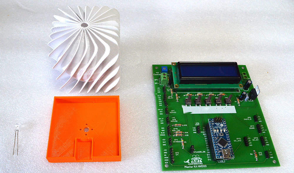
The following materials were used for the solution:
- a prototype of the debugging board of a kit for learning Arduino programming (included in the future NR05 kit), designed for the Arduino Nano ;
- real time clock MP1095 ;
- LEDs are different;
- piezo tweeter with built-in generator;
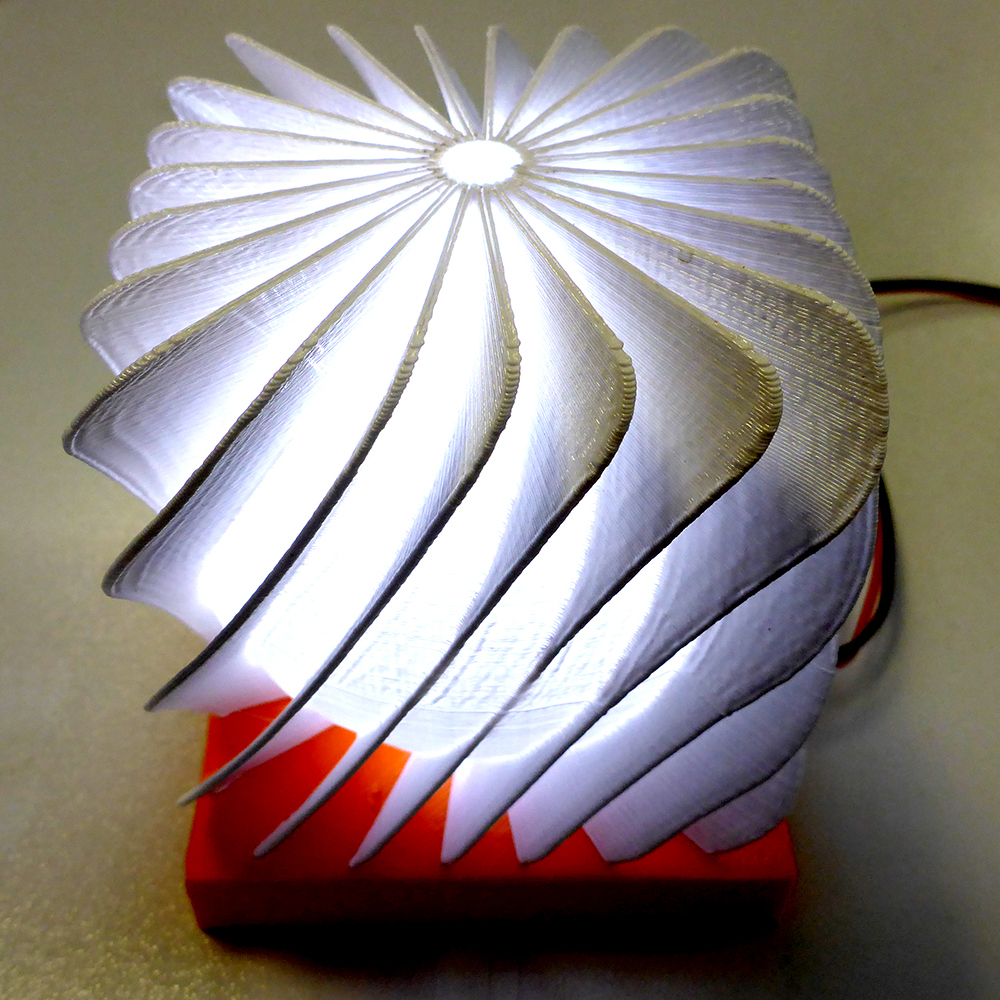
- a white translucent thing, once printed when debugging a 3D printer (you can adapt something else translucent as a diffuser, and whoever has a 3D printer can print something of their own);
- the desire to combine all this and program a suitable algorithm of work.
I wanted to pile the white thing on some pedestal in order to mount the LED there and connect it with a cable to the board. Without thinking twice, we draw in SketchUp and print an orange stand on a 3D printer. With a strong desire, you can print the case for the prototype board, but the prototype is incredibly beautiful!
In addition, it can be used for the development of other projects, and the alarm clock, according to the results of the operation of the prototype, can be arranged in a more compact design based on the same Arduino Nano board.
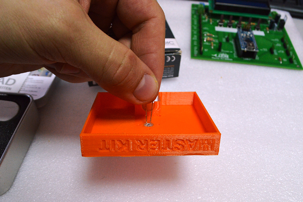
First stuck one LED. It was glued to the base with an innovative adhesive cured by UV radiation. Called Bondic. Useful thing in the household, I must say! Holds tight.
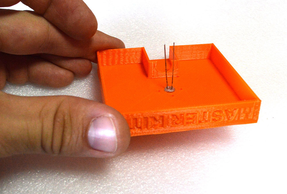
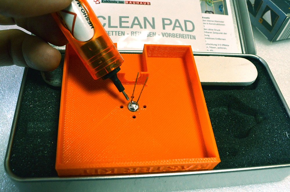
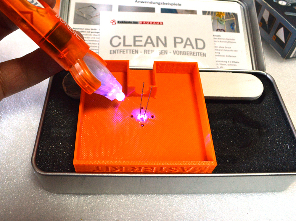
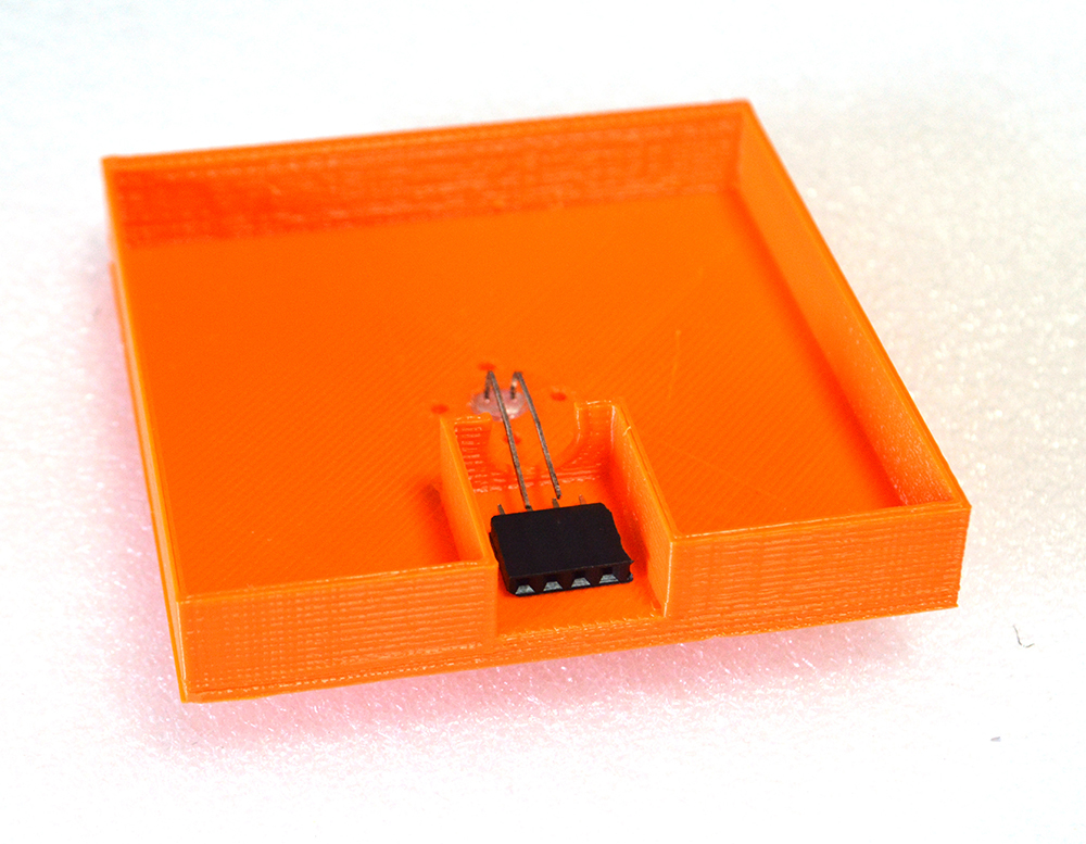
They glued the connector with the same glue.
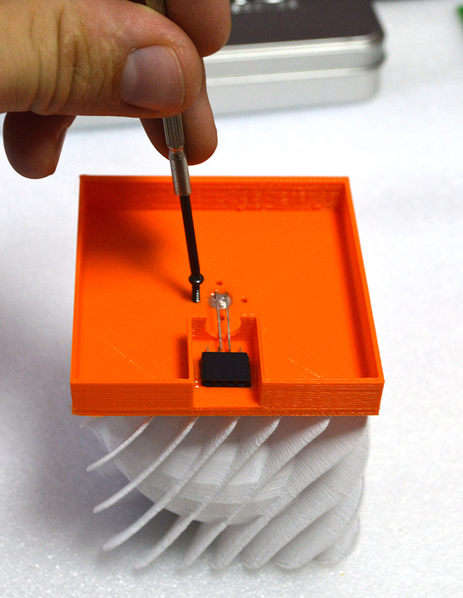
We watched how to glow. Did not like. In the dark, of course, it is visible, but not enough to activate the brain through optical receptors. A few bright white LEDs scored through the gimmicks. Combined in parallel in such a twig, they give a light quite awakening at maximum brightness.
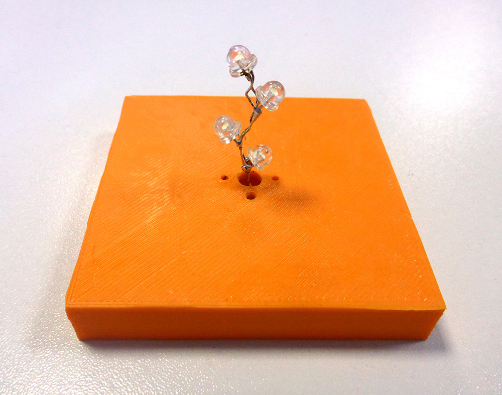
They consume a maximum of about 100 mA, you can’t connect directly to the Arduino port, but there is a transistor current amplifier on the debug board that provides 200 mA.
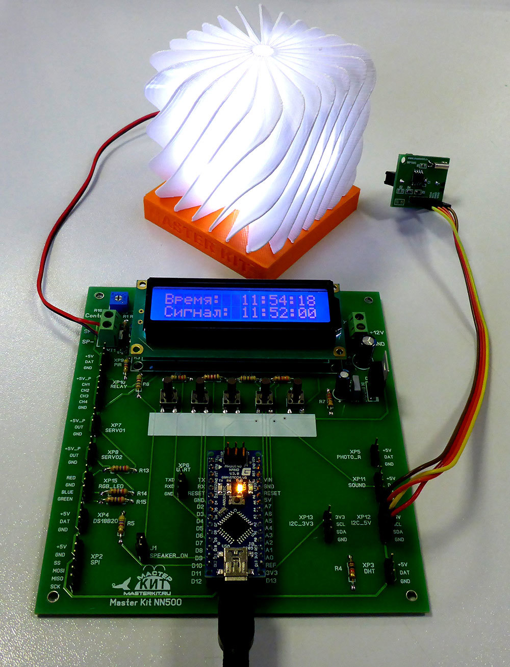
There are also five buttons on the board for all kinds of experiments, we use them to control the modes and set the alarm.
In general, the debug board is interesting by the presence of marked connectors-pins for connecting various sensors and actuators, providing good functionality and a user-friendly interface - you can connect temperature sensors, pressure sensors, servos, relays, devices with I2C interface without hesitation (signed connectors) and etc. For connection, only wires with sockets are needed.
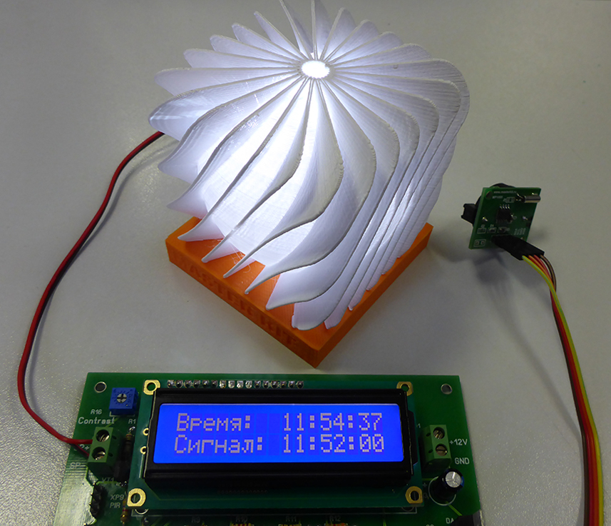
We will adjust the brightness with a PWM from the ninth pin of Arduino, which is divorced on the board to the amplifier. We connect the tweeter to the SOUND connector, on DAT plus, on GND minus. Real-time clock - to the I2C_5V connector, since they need 5V for power supply. The board already has a two-line LCD indicator, very contrasting, with nice white characters on a blue background.
Actually, all the hardware is in place, now it's up to the software.
The algorithm was conceived as follows:
- when the current time coincides with the time for which the alarm is set, the brightness of the lamp should slowly increase to the full;
- at the same time, sound signals should be emitted several times in increasing order, preventing the wakeUp object from shoving into the light bulb and falling asleep in the light;
- you must give the opportunity to turn off in the end annoying sound, as well as turn on the full light manually, or turn it off, already being fully conscious.
- It should be possible to set the time on the clock and alarm clock.
The resulting sketch is shown at the end of the material and provided with detailed comments. It is easy to modify to your desires and preferences.
Have a nice awakening for everyone!
ps Attention! From September 23 to October 23, 2015 we hold a photo contest
“3 D printing for solving everyday problems”!
The winner will receive a 3D printer-designer MC5 with an acrylic case as a gift .
Those who wish can simply drop by and vote for their favorite work.
Photo contest conditions .
Winter is inexorably looming ahead - it is dark in the morning and dark in the evening.
Waking up on an alarm clock in complete darkness is equivalent to diving under the ice. Stress in the morning - guaranteed a dull day.
The solution is, the light alarm is called, but the price of this thing is from 5000 rubles. It pricks, however. In addition, the operation algorithm is hard-coded, but it is quite obvious that, according to the results of waking up, you will want to correct something or expand the functionality.
But what if on the basis of improvised means to build something in this spirit? Good puzzle for DIY!
The following materials were used for the solution:
- a prototype of the debugging board of a kit for learning Arduino programming (included in the future NR05 kit), designed for the Arduino Nano ;
- real time clock MP1095 ;
- LEDs are different;
- piezo tweeter with built-in generator;
- a white translucent thing, once printed when debugging a 3D printer (you can adapt something else translucent as a diffuser, and whoever has a 3D printer can print something of their own);
- the desire to combine all this and program a suitable algorithm of work.
I wanted to pile the white thing on some pedestal in order to mount the LED there and connect it with a cable to the board. Without thinking twice, we draw in SketchUp and print an orange stand on a 3D printer. With a strong desire, you can print the case for the prototype board, but the prototype is incredibly beautiful!
In addition, it can be used for the development of other projects, and the alarm clock, according to the results of the operation of the prototype, can be arranged in a more compact design based on the same Arduino Nano board.
First stuck one LED. It was glued to the base with an innovative adhesive cured by UV radiation. Called Bondic. Useful thing in the household, I must say! Holds tight.
They glued the connector with the same glue.
We watched how to glow. Did not like. In the dark, of course, it is visible, but not enough to activate the brain through optical receptors. A few bright white LEDs scored through the gimmicks. Combined in parallel in such a twig, they give a light quite awakening at maximum brightness.
They consume a maximum of about 100 mA, you can’t connect directly to the Arduino port, but there is a transistor current amplifier on the debug board that provides 200 mA.
There are also five buttons on the board for all kinds of experiments, we use them to control the modes and set the alarm.
In general, the debug board is interesting by the presence of marked connectors-pins for connecting various sensors and actuators, providing good functionality and a user-friendly interface - you can connect temperature sensors, pressure sensors, servos, relays, devices with I2C interface without hesitation (signed connectors) and etc. For connection, only wires with sockets are needed.
We will adjust the brightness with a PWM from the ninth pin of Arduino, which is divorced on the board to the amplifier. We connect the tweeter to the SOUND connector, on DAT plus, on GND minus. Real-time clock - to the I2C_5V connector, since they need 5V for power supply. The board already has a two-line LCD indicator, very contrasting, with nice white characters on a blue background.
Actually, all the hardware is in place, now it's up to the software.
The algorithm was conceived as follows:
- when the current time coincides with the time for which the alarm is set, the brightness of the lamp should slowly increase to the full;
- at the same time, sound signals should be emitted several times in increasing order, preventing the wakeUp object from shoving into the light bulb and falling asleep in the light;
- you must give the opportunity to turn off in the end annoying sound, as well as turn on the full light manually, or turn it off, already being fully conscious.
- It should be possible to set the time on the clock and alarm clock.
The resulting sketch is shown at the end of the material and provided with detailed comments. It is easy to modify to your desires and preferences.
Have a nice awakening for everyone!
Sketch of the program of the alarm clock
. // Подключаем библиотеки вывода кириллицы на индикатор
#include <LiquidCrystalRus.h>
#include <LiquidCrystalExt.h>
#include <LineDriver.h>
// Подключаем библиотеку последовательной шины I2C
#include <Wire.h>
// Подключаем библиотеку часов реального времени RTC
#include «RTClib.h»
// Подключаем библиотеку для использование встроенного таймера 2
// для управления временными интервалами сигнала
#include <MsTimer2.h>
//-----------------------------------------------------------------------
#define NUM_KEYS 5
// Для каждой кнопки заносим калибровочные значения (выведены экспериментально)
int adcKeyVal[NUM_KEYS] = {30, 150, 360, 535, 760};
//-----------------------------------------------------------------------
int led13 = 13; // встроенный в Arduino Nano светодиод
int alarmPin = 3; // пин для управления сигналом будильника
int led = 9; // пин вывода ШИМ на светодиодную лампу
int brightness = 0; // начальная яркость
int riseAmount = 1; // шаг увеличения яркости 0-255
int timeAmount = 500; // шаг времени, мс
int beepCount = 0; // служебные переменные
int numberOfBeeps = 0;
unsigned long time_old;
unsigned long time_curr;
int alarm = 0; // флаг срабатывания будильника
int Step; // служебные переменные
unsigned long tSetOld;
unsigned long tTickOld;
// Создаем программный объект дисплей lcd, объясняя программе куда подключены линии RS,EN,DB4,DB5,DB6,DB7
LiquidCrystalRus lcd(A1, A2, A3, 2, 4, 7);
// Создаем программный объект RTC
RTC_DS1307 RTC;
int Year; // переменные для хранения данных с RTC
int Month;
int Day;
int Hour;
int Minute;
int Second;
int alarmHour = 0;
int alarmMinute = 0;
int setAlarm = 0; // будильник вкл./выкл.
int SetMode = 0; // режим установки часов/будильника вкл./выкл.
int AlarmOn; // сигнал вкл./выкл.
void setup() {
pinMode(led13, OUTPUT);
pinMode(3, OUTPUT);
lcd.begin(16, 2);
Wire.begin(); // инициализируем 1Wire (необходио для RTC)
RTC.begin(); // инициализируем RTC
RTC.writenvram(2, 0); // секунды сигнала устанавливаем в 00 (ячейка 2 постоянной памяти RTC)
tTickOld = millis(); // запомнаем число мс с момента запуска микроконтроллера для отсчета интервалов времени
// если нажата кнопка 5, установить текущее время из компьюьера на момент компиляции программы
// и сбросить будильник в 0
if (get_key() == 5) {
RTC.adjust(DateTime(__DATE__, __TIME__));
for (int i = 0; i < 5; i++) RTC.writenvram(i, 0);
}
}
void loop() {
AlarmOn = RTC.readnvram(3); // читаем 3-ю ячейку памяти RAM RTC: будильник включен (1) или выключен (0)
if (get_key() == 2) { // если нажата кнопка 2
SetMode++; // вход в режим установки часов
delay(500);
tSetOld = millis();
}
while (SetMode) { // установка показаний часов и будильника
if (get_key() == 2) {
SetMode++;
delay(200);
tSetOld = millis();
}
if (SetMode > 4) { // выход из режима установки
SetMode = 0;
lcd.noBlink();
lcd.noCursor();
}
switch (SetMode) { // установка мигающего курсора
case 1:
lcd.setCursor(12, 1); lcd.blink();
break;
case 2:
lcd.setCursor(9, 1); lcd.blink();
break;
case 3:
lcd.setCursor(12, 0); lcd.blink();
break;
case 4:
lcd.setCursor(9, 0); lcd.blink();
break;
}
if (get_key() == 1 or get_key() == 3) { // если нажата кнопка 1 или 3
tSetOld = millis(); // обнуляем счетчик нахождения в режиме установки
if (get_key() == 3) Step = 1; // если кнопка 3 — увеличиваем
if (get_key() == 1) Step = -1; // если кнопка 1 — уменьшаем
switch (SetMode) {
case 1:
SetMinuteAlarm(Step); // минуты будильника
break;
case 2:
SetHrAlarm(Step); // часы будильника
break;
case 3:
SetMinute(Step); // минуты текущего времени
break;
case 4:
SetHr(Step); // часы текущего времени
break;
}
}
if ((millis() — tTickOld) > 1000) {
displayTime(); // раз в секунду отображаем время на индикаторе в режиме установки
tTickOld = millis();
}
if ((millis() — tSetOld) > 10000) {
SetMode = 0; // автовыход из режима установки через 10 сек.
lcd.noBlink();
}
} // end SetMode
if (get_key() == 4) { // включаем/выключаем будильник
int alarm_ram = RTC.readnvram(3);
RTC.writenvram(3, !alarm_ram);
delay(50);
AlarmOn = alarm_ram;
delay(500);
}
if (get_key() == 5) { // выключение света вручную
alarm = 0;
digitalWrite(led13, LOW);
lightDown();
}
if (get_key() == 5 && brightness >= 0) { // включение света вручную
lightUp();
}
if (get_key() == 1 && !SetMode) { // выключение звука сработавшего будильника
//alarm = 0;
MsTimer2::stop();
digitalWrite(alarmPin, LOW);
}
if ((millis() — tTickOld) > 1000) {
displayTime(); // раз в секунду отображаем время на индикаторе
tTickOld = millis();
}
if (alarm == 1) // если будильник сработал
{
digitalWrite(led13, HIGH);
time_curr = millis();
if ((time_curr — time_old) > timeAmount) {
if (brightness < 255) {
brightness = brightness + riseAmount;
time_old = time_curr;
if (brightness > 255) brightness = 255;
analogWrite(led, brightness); // медленно повышаем яркость с помощью ШИМ
switch (brightness) { // пищим пьезодинамиком по мере повышения яркости
case 60:
numberOfBeeps = 4;
alarmRun();
break;
case 120:
numberOfBeeps = 4;
alarmRun();
break;
case 180:
numberOfBeeps = 8;
alarmRun();
break;
case 220:
numberOfBeeps = 14;
alarmRun();
break;
}
if (brightness >= 255) {
numberOfBeeps = 32000; // пищим непрерывно (32000 раз)
alarmRun();
}
}
else digitalWrite(led13, LOW);
}
}
} // end loop
//----------------------------------------------
int get_key() // функция считывания номера нажатой кнопки
{
int input = analogRead(A6);
int k;
for (k = 0; k < NUM_KEYS; k++)
if (input < adcKeyVal[k])
return k + 1;
return 0;
}
void SetMinuteAlarm(int Step) { // установка минут будильника
alarmMinute = RTC.readnvram(1);
alarmMinute += Step;
if (alarmMinute > 59) alarmMinute = 0;
if (alarmMinute < 0) alarmMinute = 59;
RTC.writenvram(1, alarmMinute);
delay(300);
}
void SetHrAlarm(int Step) { // установка часов будильника
alarmHour = RTC.readnvram(0);
alarmHour += Step;
if (alarmHour > 23) alarmHour = 0;
if (alarmHour < 0) alarmHour = 23;
RTC.writenvram(0, alarmHour);
delay(300);
}
void SetMinute(int Step) { // установка минут времени
DateTime now = RTC.now();
Year = now.year();
Month = now.month();
Day = now.day();
Hour = now.hour();
Minute = now.minute();
Second = now.second();
Minute += Step;
if (Minute > 59) Minute = 0;
if (Minute < 0) Minute = 59;
RTC.adjust(DateTime(Year, Month, Day, Hour, Minute, Second));
delay(300);
}
void SetHr(int Step) { // установка часов часов
DateTime now = RTC.now();
Year = now.year();
Month = now.month();
Day = now.day();
Hour = now.hour();
Minute = now.minute();
Second = now.second();
Hour += Step;
if (Hour > 23) Hour = 0;
if (Hour < 0) Hour = 23;
RTC.adjust(DateTime(Year, Month, Day, Hour, Minute, Second));
delay(300);
}
void displayTime() { // вывод на индикатор
DateTime now = RTC.now();
Year = now.year() — 2000;
Month = now.month();
Day = now.day();
Hour = now.hour();
Minute = now.minute();
Second = now.second();
lcd.setCursor(0, 0);
lcd.print(«Время: „);
if (Hour < 10) lcd.print(' ');
lcd.print(Hour);
lcd.print(':');
if (Minute < 10) lcd.print('0');
lcd.print(Minute);
lcd.print(':');
if (Second < 10) lcd.print('0');
lcd.print(Second);
int h = RTC.readnvram(0);
int m = RTC.readnvram(1);
int s = RTC.readnvram(2);
if (AlarmOn) {
lcd.setCursor(0, 1);
lcd.print(“Сигнал: „);
if (h < 10) lcd.print(' ');
lcd.print(h);
lcd.print(':');
if (m < 10) lcd.print('0');
lcd.print(m);
lcd.print(':');
if (s < 10) lcd.print('0');
lcd.print(s);
}
else {
lcd.setCursor(0, 1);
lcd.print(“Сигнал: --:--:--»);
}
if (Hour == h && Minute == m && Second == s && AlarmOn) { // срабатывание будильника!
alarm = 1;
numberOfBeeps = 2;
alarmRun();
}
}
void lightDown() { // плавное выключение светодиода
while (brightness > 0) {
time_curr = millis();
if ((time_curr — time_old) > 10) {
if (brightness > 0) {
brightness = brightness — 1;
time_old = time_curr;
if (brightness < 1) brightness = 0;
analogWrite(led, brightness);
}
}
}
}
void lightUp() { // плавное выключение светодиода
while (brightness < 255) {
time_curr = millis();
if ((time_curr — time_old) > 10) {
if (brightness < 255) {
brightness++;
time_old = time_curr;
if (brightness > 255) brightness = 255;
analogWrite(led, brightness);
}
}
}
}
void alarmRun() { // включение сигнала 1 раз (один бип)
digitalWrite(alarmPin, HIGH);
beepCount = 0;
MsTimer2::set(500, beep); // 500ms period
MsTimer2::start();
}
void beep() { // выключение сигнала через 500 мс по прерыванию от таймера 2
if (beepCount < numberOfBeeps) {
static boolean output = HIGH;
digitalWrite(alarmPin, output);
output = !output;
beepCount++;
}
else {
MsTimer2::stop();
digitalWrite(alarmPin, LOW);
}
}
ps Attention! From September 23 to October 23, 2015 we hold a photo contest
“3 D printing for solving everyday problems”!
The winner will receive a 3D printer-designer MC5 with an acrylic case as a gift .
Those who wish can simply drop by and vote for their favorite work.
Photo contest conditions .
