While it is raining. Calculate lightning
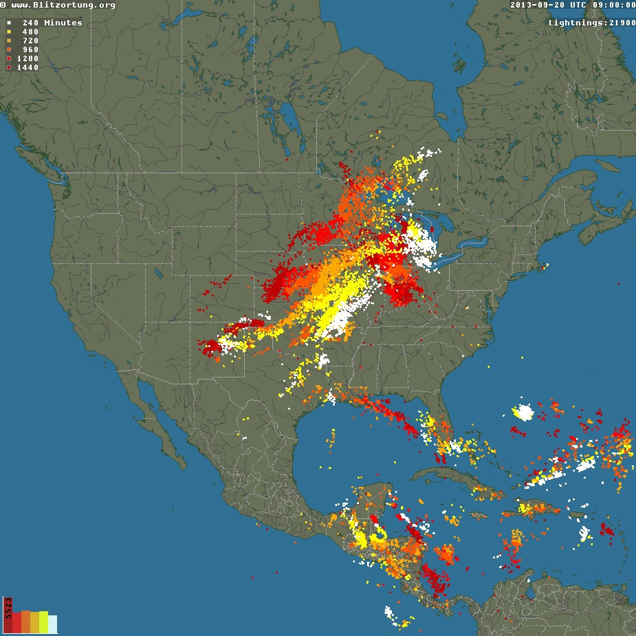
The aim of the Blitzortung.org project is to create a low-budget network of stations for high-precision location of lightning. This is achieved due to the large number of receiving stations located close to each other, as a rule, at a distance of 50 km - 250 km. These stations transmit their data to a central server, where the places of lightning flashes are calculated by the time of arrival of the signals. The owners of these receivers are volunteers who buy or assemble equipment on their own. There is also a team of volunteer programmers who develop and implement location and visualization algorithms and people who help maintain the health of the entire system. Lightning locations are available free of charge in the original format for those participants whose stations transmit their data to the project server.
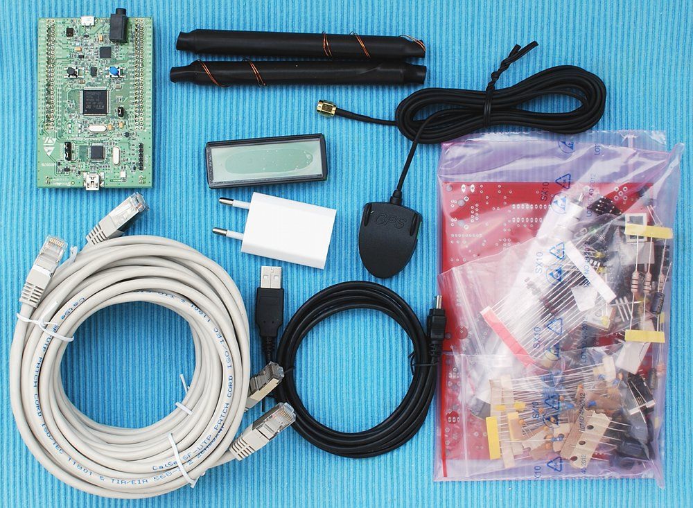
The equipment required to participate in the network consists of an antenna system, a VLF (VLF) amplifier, a controller board, and a GPS receiver that provides a 1PPS signal (one pulse per second).
Parts order
Interested people can get the necessary details from the Blitzortung.org project. For participants not from Germany, sometimes complete sets are sent, as shown in the figure. The total price for the necessary parts is about 200 euros. Only some parts can be ordered if you really have enough time and desire to assemble a lightning detector. Please note that we may improve the circuit board from time to time. Most parts of the equipment are standard components, printed circuit boards are made only by us. Please do not try to do this yourself and do not make any changes on the printed circuit boards, especially on the amplifier. This is important for the accuracy of calculating the location of the lightning, all participating receiving stations should behave identically. Otherwise, the accuracy of the calculations will drop!
It cannot be guaranteed that the receiving station will work well anywhere. Electrical devices can cause interference, such as power supplies, computers, energy-saving lamps, CRT monitors, televisions, etc. In some cases, stations with a lot of interference should be set to sub-optimal settings. For example, wire guards of robotic lawnmowers or large power lines with high voltage produce very strong interference. But do not worry, data from the station will be received as long as the interference is occasional. It is also not a problem if the receiving station does not transmit data for some time daily due to interference or other circumstances.
Bit of theory
How lightning initially forms is still a matter of debate. Scientists have studied the causes, from basic atmospheric disturbances (wind, humidity, friction, and atmospheric pressure) to exposure to the solar wind and the accumulation of charged solar particles. Ice inside the cloud is considered a key element in the development of lightning, and can lead to the violent separation of positive and negative charges in the cloud and thus contribute to the formation of lightning.
The fact that lightning has an electrical nature was not obvious, since electric current does not flow through the air. On June 10, 1752, Benjamin Franklin launched a kite during a thunderstorm, when lightning struck the kite, a charge was collected in a Leyden jar, which allowed him to demonstrate the electric nature of lightning. He also invented the lightning rod used to protect buildings and ships.
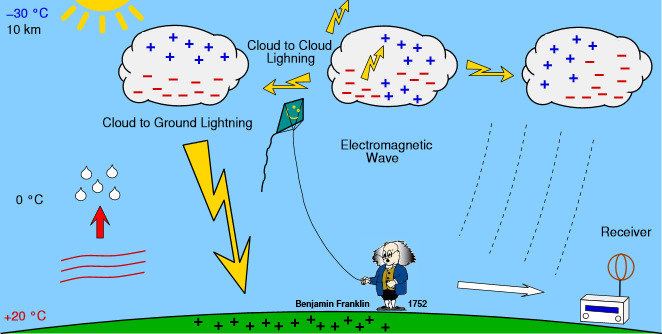
A lightning bolt emits energy at radio frequencies in a wide frequency range. When high currents occur in previously ionized channels during cloud-to-ground flares, the most powerful emissions occur in the VLF range.
VLF - Very low frequency
VLF - Very low frequency. Frequencies from 3 kHz to 30 kHz which corresponds to wavelengths from 10 to 100 kilometers. The most powerful lightning discharges occur precisely in the VLF range.
A significant advantage of low frequencies, in contrast to higher frequencies, is the ability of these signals to travel thousands of kilometers when reflected from the ionosphere and the earth.
A lightning discharge generates several pulses of short duration launched between a thundercloud and ground, or between thunderclouds. The current creates an electric field parallel to the direction of its flow, and the corresponding magnetic field perpendicular to the electric field.
Lightning signal reception
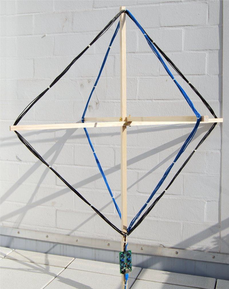
Waves with a frequency from 3 kHz to 30 kHz have a length between 100 and 10 km. A suitable antenna for these frequencies is a small loop antenna with a size of less than 1/10000 of the wavelength. Small loops are also called magnetic because they are more sensitive to the magnetic component of the electromagnetic wave and less sensitive to electrical noise when properly shielded. If the loop is shorter than the wavelength, then the current around the antenna will be almost completely in phase. Thus, waves approaching in the plane of the loop will not be received, and the reception of waves along an axis perpendicular to the plane of the loop will be maximum. This property changes if the loop becomes larger. The polarization of cloud-to-ground lightning discharges is mostly vertical, so the magnetic field is oriented horizontally. For circular coverage (360 degrees), it is advisable to use more than one loop. A suitable solution can be obtained using two mutually perpendicular crossed loops, such a solution is used in direction finding systems.
The electromagnetic signals of lightning discharges are not waves of a fixed frequency. The signals have a more or less pulse shape and therefore emits waves in a wide frequency range. Each of these impulses is unique and looks different.
Description of the receiving part
To measure the time of arrival of a lightning strike, we must have a broadband reception system, not a tuned system. The antenna should be large enough to capture changes in the electromagnetic field. If the loop consists of several windings, then a capacitance is formed between adjacent turns.
The natural resonant frequency of the loop should be as high as possible, so that we can suppress these frequencies with a low-pass filter. The figure on the left shows the signal received at the antenna from two equal-sized detuned loops. These loops do not have any additional tuning capacitors.
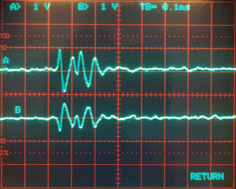
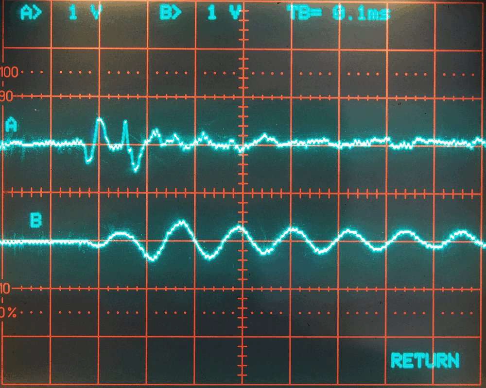
The resonant frequency of the antenna is approximately 1000 kHz (1 MHz). The amplifier used reduces the frequency by 1000 kHz -72 dB (4000 times). In the figure on the right, loop B with a 1 μF parallel-connected tuning capacitor. Now, the antenna is tuned to approximately 10 kHz. Since lightning pulses often contain a lot of energy at 10 kHz, the tuned antenna circuit only outputs unused 10 kHz uniform waves. This shows that it is very important to use a clean loop without a parallel capacitor.
The natural resonant frequency of the loop should be as high as possible, so that we can suppress these frequencies with a low-pass filter. The figure on the left shows the signal received at the antenna from two equal-sized detuned loops. These loops do not have any additional tuning capacitors.
The resonant frequency of the antenna is approximately 1000 kHz (1 MHz). The amplifier used reduces the frequency by 1000 kHz -72 dB (4000 times). In the figure on the right, loop B with a 1 μF parallel-connected tuning capacitor. Now, the antenna is tuned to approximately 10 kHz. Since lightning pulses often contain a lot of energy at 10 kHz, the tuned antenna circuit only outputs unused 10 kHz uniform waves. This shows that it is very important to use a clean loop without a parallel capacitor.
TOA method (time of arrival
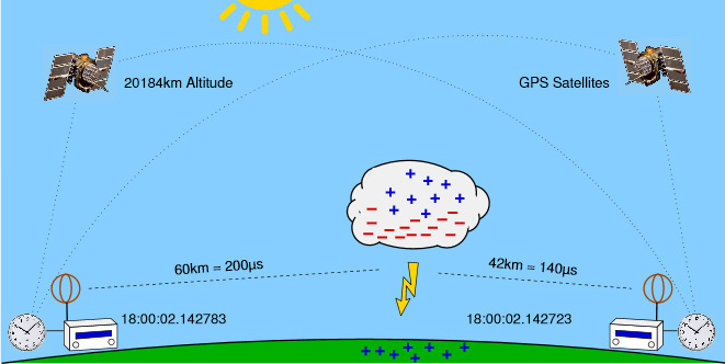
method ) The method of determining the location of the TOA lightning is based on calculations of hyperbolic curves. The emitted radio signal from a lightning bolt moves through the air at the speed of light. This is about 300,000 kilometers per second or 300 meters per microsecond. Each received signal receives a time stamp. Let tA (s) will be a time stamp for the signal s from the station A . The time stamp tA (s) is set in UTC (Coordinated Universal Time) in microseconds with an accuracy of 1 μs. The difference of two time stamps for one signal received by two different stations and the difference of the positions of these stations can be specified by a hyperbolic curve. Let dA (p)distance from point p to station A in meters. The hyperbolic curve for signal s is the set of all positions of point p corresponding to the distance difference dA (p) - dB (p) in meters in the corresponding time stamps of the difference tA (s) - tB (s) in microseconds converted by the speed of light to meter .
dA (p) - dB (p) = (tA (s) - tB (s)) * 300
The signal source must be somewhere on this hyperbolic curve. The intersection point of three or more of these hyperbolic curves defines the unique location of the radio source.
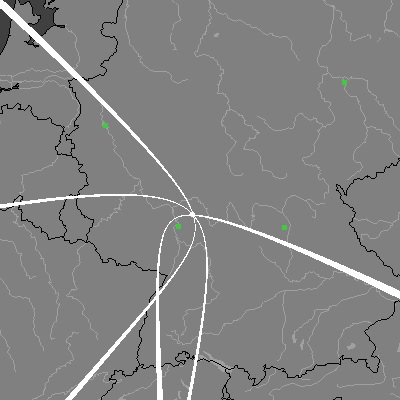
The calculated position will be considered the location of the lightning discharge. To determine a unique crossing point, at least 4 stations are not located on the same line. If the signal is received from more than four stations, then some redundant information will improve accuracy. The intersection of all three curves uniquely determines the location of the radio signal source (white dot).
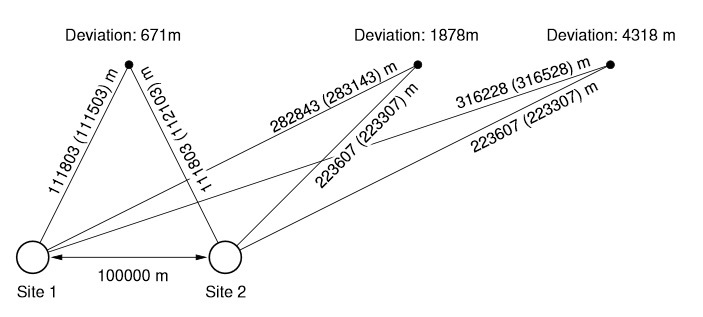
A time difference of ± 100 μs corresponds to a distance difference of ± 30 kilometers. That is, if station A receives the same signal 100 μs earlier than station B, then all points of the corresponding hyperbolic curve will be 30 km closer to station A than B. Suppose that the time stamps have an accuracy of ± 1 μs and there are Four stations located so that their positions define a square. If the signal source is exactly in the middle of the square, then the accuracy of determining the location will be less than 300m * √2 = 424 m. The accuracy can be much less if the signal source is outside the square.
The argument of some commercial suppliers that their system has an accuracy of 300m, because the mark has an accuracy of 1 μs, is a naive misconception.
The main complexity of the TOA system is the recognition of the uniqueness of the received signal. This is not easy because the signal circuit changes when it travels long distances. The only way to deal with various waveforms is to calculate the arrival time of the group. However, if the timestamp is not assigned sequentially, then the hyperbolic curves do not intersect at a common intersection point.
Calculations on the server are carried out in two stages. At the first stage, the starting point is calculated from the first 4 time stamps, then using the numerical method. All calculations use spherical coordinates.
Blitzortung.org Network
The Blitzortung.org lightning location network consists of VLF receiving stations and one central processing server for each large area. Receiving stations transmit their data in real time via the Internet to the server. Each package contains data on the exact time of the received lightning strike and the coordinates of the receiver.
Based on this information, the exact positions of the bits are calculated. Spherical coordinates are available in the original format for all users who transmit their data to the server. Users can use the source data for any non-commercial purposes. The lightning activity of the last two hours is displayed on the Blitzortung.org website on several public maps and is recounted every minute. It should be noted that it is not possible to calculate the position or exact directions with the data of one station. At least four stations are needed to calculate lightning strike positions. There is currently no software that allows you to connect to other direction finding systems, such as LR software of LightningRadar.net. Lightning strike position calculations are done by only one of the Blitzortung.org computing servers.
More information about the project, receive antenna models, hardware and software can be found in www.blitzortung.org/Documents/TOA_Blitzortung_RED.pdf .
This publication is a translation of the introduction to this document.