Auto calibration of the delta printer, using the Prism Mini as an example
In a previous article , it was shown how to calibrate the delta printer in manual mode. But due to the complexity and complexity of the settings, it was decided to do auto calibration. Since the final version is at the testing and manufacturing stage, we still want to make life easier for our customers, and for everyone who made printers for themselves according to this scheme. Next, one of the ways to implement auto calibration will be considered.
There are many approaches, installing a retractable probe on an ejector with a microswitch, FSR sensors, a Hall sensor, etc. But these systems have a significant drawback - they measure the distance not to the nozzle, but directly to the sensor, plus, in some cases, alignment may fail (if the sensor is not located instead of the nozzle, the geometry calculation may be violated. Not to mention accuracy) .
The ideal option is to fix the touch of the nozzle itself on the table. And here you can go in two ways:
The first option is more complicated in the manufacture and stability of work, but with proper design it will give a permanent stable result, without additional body movements.
The second option is less convenient to use, but it is simple to implement, and most often calibration is rarely required and can be done as needed.
We will tell about the second method:
From the tool we need:
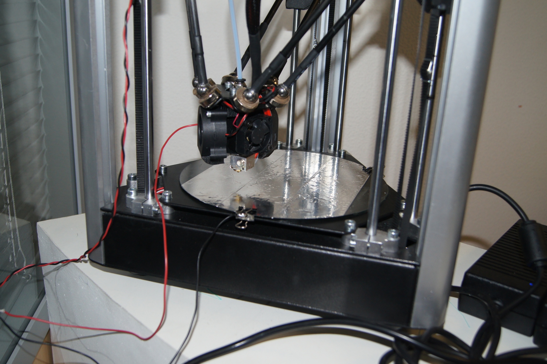
The simplest way to apply a current-conducting layer to our work plane (glass) was a sticker of aluminum tape, but it is important to stick it evenly and smooth it so that there is electrical contact between the tape strips, it is checked elementarily with a multimeter for “ringing”.

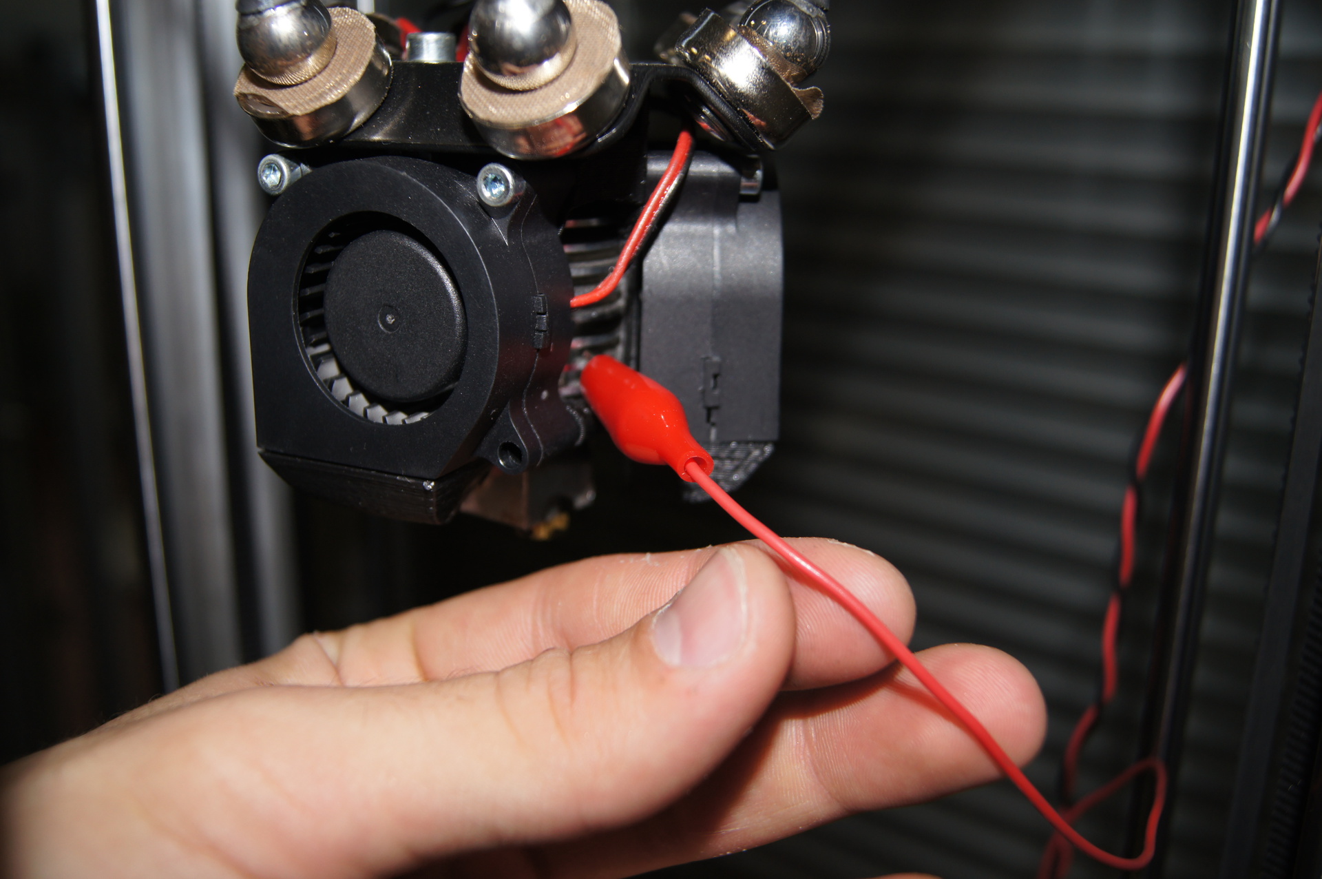
Also, for switching, you should make a wire, as it was written earlier, squeeze one of the ends into a block 2.54 (or solder to it), the other two ends will be fixed on the HotEnd's radiator and on the table with aluminum tape. In order to crawl to the radiator we take an ordinary crocodile and solder one of the ends of the wire to it, I advise using acid for ease of soldering, although I managed it with good heating and ordinary rosin, but the second end can also be soldered to the crocodile, but in this case there is a chance to damage the adhesive tape when fixed, and the crocodile should be large enough. We did the following: take a paper clip and clean it from paint (preferably from all sides). The important point here is

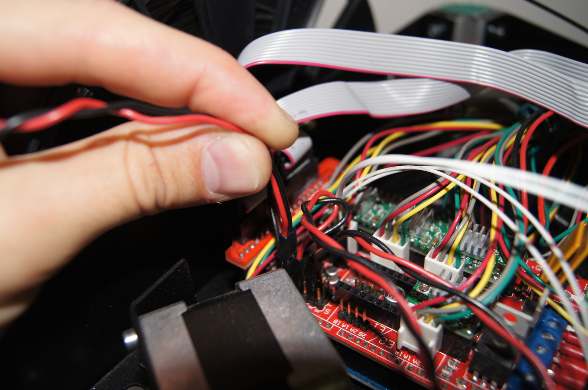
The following are photos of the connection to the board and to the printer itself. The ends of the wires on our printer are connected to the Z-max., And in the firmware it is necessary to indicate what is the normal state of the limit switch (our sensor, closed or open). With this approach, the sensor is open in normal condition.


Firmware with auto calibration for delta printers can be taken from here: Marlin Delta firmware with autocalibration updates. RichCattell
Firmware Settings:
Cohfiguration.h
After connecting the wires and adjusting the printer firmware, you need to start the calibration itself. And here is a very important point that calibration should be done from a computer, because The printer itself does not perform this operation correctly. Apparently there is not enough device memory and calibration ends somewhere in the middle.
Also, one of the features of auto calibration is that the algorithm sequentially selects the geometry parameters, which can take a considerable time, especially if the geometry is severely broken or the initial parameters are not correctly set (for example, the length of the diagonals is 150 mm, and in fact 200 mm, and the algorithm with the given step will repeat the calibration every iteration again, in the end it will be calibrated, but it will take an inconceivable amount of time)
To start auto calibration, connect to the printer via USB, and use the pronterface program. There are three types of calibration:
Accordingly, the last two are most relevant.
The following is a listing of the printer console without initial calibration and restarting it.
Brief Calibration Principle:
There are many approaches, installing a retractable probe on an ejector with a microswitch, FSR sensors, a Hall sensor, etc. But these systems have a significant drawback - they measure the distance not to the nozzle, but directly to the sensor, plus, in some cases, alignment may fail (if the sensor is not located instead of the nozzle, the geometry calculation may be violated. Not to mention accuracy) .
The ideal option is to fix the touch of the nozzle itself on the table. And here you can go in two ways:
- Create an electrical contact between the HotEnd and the ejector so that the HotEnd is movable and opens (or closes) the contact when pressed.
- Create an electrical contact between the metal nozzle and the table.
The first option is more complicated in the manufacture and stability of work, but with proper design it will give a permanent stable result, without additional body movements.
The second option is less convenient to use, but it is simple to implement, and most often calibration is rarely required and can be done as needed.
We will tell about the second method:
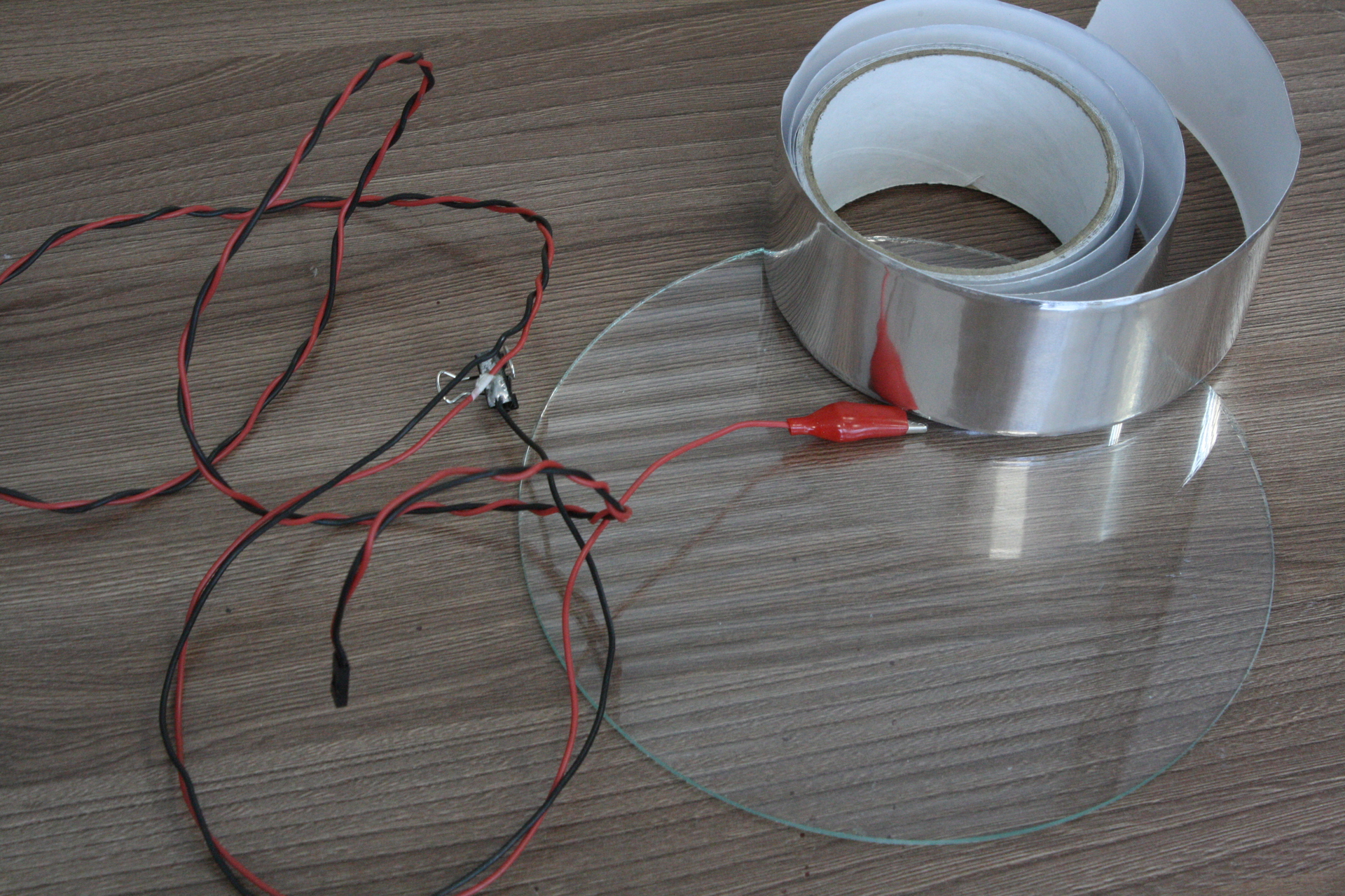
From the tool we need:
- Aluminum scotch tape (in fact, it is aluminum foil on an adhesive basis, and not all kinds of reinforcing tapes there)
- “Crocodile” - to connect one of the contacts to the hot-end metal case, in principle, you can do with any paper clip, or fix the end of the wire by screwing it or soldering it (severely but effectively)
- Office clothespin
- Pin block 2.54 for connecting our makeshift sensor to the RAMPS 1.4 board (or to the corresponding EndStop connector on your board). Few people have a crimp for mounting such blocks, but you can find a similar block in the computer unit by removing it from the “tweeter” or buttons.
- Soldering accessories, it is desirable to have an active flux and a less powerful soldering iron.
- Wires, about a meter.
The simplest way to apply a current-conducting layer to our work plane (glass) was a sticker of aluminum tape, but it is important to stick it evenly and smooth it so that there is electrical contact between the tape strips, it is checked elementarily with a multimeter for “ringing”.
Also, for switching, you should make a wire, as it was written earlier, squeeze one of the ends into a block 2.54 (or solder to it), the other two ends will be fixed on the HotEnd's radiator and on the table with aluminum tape. In order to crawl to the radiator we take an ordinary crocodile and solder one of the ends of the wire to it, I advise using acid for ease of soldering, although I managed it with good heating and ordinary rosin, but the second end can also be soldered to the crocodile, but in this case there is a chance to damage the adhesive tape when fixed, and the crocodile should be large enough. We did the following: take a paper clip and clean it from paint (preferably from all sides). The important point here is
The following are photos of the connection to the board and to the printer itself. The ends of the wires on our printer are connected to the Z-max., And in the firmware it is necessary to indicate what is the normal state of the limit switch (our sensor, closed or open). With this approach, the sensor is open in normal condition.
Firmware with auto calibration for delta printers can be taken from here: Marlin Delta firmware with autocalibration updates. RichCattell
Firmware Settings:
Cohfiguration.h
// Precision for G30 delta autocalibration function
#define AUTOCALIBRATION_PRECISION 0.03 // mm. Точность калибровки, используемая нами была равна 0.1мм.
// Diameter of print bed - this is used to set the distance that autocalibration probes the bed at. Диаметр печатного стола, параметр используется для задания размера для авто калибровке, чем дальше расположены точки (больше диаметр), тем лучше, но при касании (в нашем случае, т.к. эфектор на магнитах) может отвалится эффектор.
#define BED_DIAMETER 170 // mm
// The pullups are needed if you directly connect a mechanical endswitch between the signal and ground pins.
const bool X_MIN_ENDSTOP_INVERTING = false; // set to true to invert the logic of the endstop.
const bool Y_MIN_ENDSTOP_INVERTING = false; // set to true to invert the logic of the endstop.
const bool Z_MIN_ENDSTOP_INVERTING = false; // set to true to invert the logic of the endstop.
const bool X_MAX_ENDSTOP_INVERTING = false; // set to true to invert the logic of the endstop.
const bool Y_MAX_ENDSTOP_INVERTING = false; // set to true to invert the logic of the endstop.
const bool Z_MAX_ENDSTOP_INVERTING = true; // set to true to invert the logic of the endstop. Нас интересует именно этот параметр
After connecting the wires and adjusting the printer firmware, you need to start the calibration itself. And here is a very important point that calibration should be done from a computer, because The printer itself does not perform this operation correctly. Apparently there is not enough device memory and calibration ends somewhere in the middle.
Also, one of the features of auto calibration is that the algorithm sequentially selects the geometry parameters, which can take a considerable time, especially if the geometry is severely broken or the initial parameters are not correctly set (for example, the length of the diagonals is 150 mm, and in fact 200 mm, and the algorithm with the given step will repeat the calibration every iteration again, in the end it will be calibrated, but it will take an inconceivable amount of time)
To start auto calibration, connect to the printer via USB, and use the pronterface program. There are three types of calibration:
- The G30 command - calibrates offset's - essentially sets the height to the limit switches.
- The G30A command - calibrates the entire geometry of the printer, the length of the diagonals, the indentation of the limit switches (height) and the curvature of the geometry according to the “Tower” - towers (most likely, the printer supports different heights)
- Team G29 - the so-called AutoBedLevel - automatic table curvature calibration. On delta printers, it works most correctly, and starts immediately before printing starts in the initial g-code.
Accordingly, the last two are most relevant.
The following is a listing of the printer console without initial calibration and restarting it.
Brief Calibration Principle:
- Checking / Adjusting Endstop Offsets
- Check / Adjust Delta Radius
- Checking tower geometry errors
- Diagonal Length Selection> Checking Tower Geometry> Reconciling EndStop Offsets. When the first two parameters change, the third one is selected and the cycle is repeated until all three parameters are satisfied.
Listing of initial calibration - iterations from 4 to 17 are cut since it repeats the action
Connecting...
start
Printer is now online.
echo:Marlin 1.0.0
echo: Last Updated: Jul 31 2015 11:09:21 | Author: (RichCattell, Prism Mini)
Compiled: Jul 31 2015
echo: Free Memory: 1753  PlannerBufferBytes: 1232
echo:Hardcoded Default Settings Loaded
echo:Steps per unit:
echo:  M92 X100.00 Y100.00 Z100.00 E156.00
echo:Maximum feedrates (mm/s):
echo:  M203 X200.00 Y200.00 Z200.00 E200.00
echo:Maximum Acceleration (mm/s2):
echo:  M201 X9000 Y9000 Z9000 E9000
echo:Acceleration: S=acceleration, T=retract acceleration
echo:  M204 S3000.00 T3000.00
echo:Advanced variables: S=Min feedrate (mm/s), T=Min travel feedrate (mm/s), B=minimum segment time (ms), X=maximum XY jerk (mm/s),  Z=maximum Z jerk (mm/s),  E=maximum E jerk (mm/s)
echo:  M205 S0.00 T0.00 B20000 X20.00 Z20.00 E20.00
echo:Home offset (mm):
echo:  M206 X0.00 Y0.00 Z0.00
echo:Delta Geometry adjustment:
echo:  M666 A0.000 B0.000 C0.000 I0.000 J0.000 K0.000 U0.000 V0.000 W0.000 R66.00 D154.00 H230.00
echo:Endstop Offsets:
echo:  M666 X0.00 Y0.00 Z0.00
echo:Z-Probe Offset:
echo:  M666 P X0.00 Y0.00 Z0.00
echo:PID settings:
echo:   M301 P15.09 I0.75 D76.13
echo:SD init fail
Setting hotend temperature to 190.000000 degrees Celsius.
Setting bed temperature to 70.000000 degrees Celsius.
>>> g30 a
SENDING:G30 A
Starting Auto Calibration..
Calibration precision: +/-0.100mm
|	Z-Tower			Endstop Offsets
| 	-7.8500			X:0.00 Y:0.00 Z:0.00
| -5.2400		-8.5900		Tower Offsets
| 	-6.8400			A:0.00 b:0.00 C:0.00
| -3.7200		-8.0400		I:0.00 J:0.00 K:0.00
| 	-5.6900			Delta Radius: 66.0000
| X-Tower		Y-Tower		Diagonal Rod: 154.0000
Iteration: 1
Checking/Adjusting endstop offsets // Проверка / регулировка смещения endstop'ов
			x:-3.6800 (adj:-3.6800) y:-7.9600 (adj:-7.9600) z:-7.7700 (adj:-7.7700)
			X=ERROR Y=ERROR Z=ERROR
			x:0.7500 (adj:-2.9300) y:-0.1900 (adj:-8.1500) z:-0.2200 (adj:-7.9900)
			X=ERROR Y=ERROR Z=ERROR
			x:0.1600 (adj:-2.7700) y:-0.0800 (adj:-8.2300) z:0.0500 (adj:-7.9400)
			X=ERROR Y=OK Z=OK
			x:0.0300 (adj:-2.7400) y:-0.0200 (adj:-8.2500) z:0.0100 (adj:-7.9300)
			X=OK Y=OK Z=OK
|	Z-Tower			Endstop Offsets
| 	-0.0300			X:-2.74 Y:-8.25 Z:-7.93
| -0.0200		0.1500		Tower Offsets
| 	-0.2800			A:0.00 b:0.00 C:0.00
| -0.0300		-0.0300		I:0.00 J:0.00 K:0.00
| 	-0.1900			Delta Radius: 66.0000
| X-Tower		Y-Tower		Diagonal Rod: 154.0000
Checking delta radius //Проверка дельта радиуса
Adjusting Delta Radius //Регулировка дельта радиуса
			x:-0.0600 (adj:-2.8000) y:-0.0300 (adj:-8.2800) z:-0.0500 (adj:-7.9800)
			X=OK Y=OK Z=OK
			 c: -0.2000 delta radius:66.0000 prec:0.010 tries:0
			 done:false
			x:0.0700 (adj:-2.7300) y:0.0900 (adj:-8.1900) z:0.0300 (adj:-7.9500)
			X=OK Y=OK Z=OK
			 c: -0.2100 delta radius:66.2000 prec:0.010 tries:0
			 done:false
			x:0.0600 (adj:-2.6700) y:0.0300 (adj:-8.1600) z:0.0600 (adj:-7.8900)
			X=OK Y=OK Z=OK
			 c: -0.1500 delta radius:66.4000 prec:0.010 tries:0
			 done:false
			x:0.0400 (adj:-2.6300) y:-0.0100 (adj:-8.1700) z:0.0300 (adj:-7.8600)
			X=OK Y=OK Z=OK
			 c: -0.0800 delta radius:66.6000 prec:0.010 tries:1
			 done:false
			x:0.0300 (adj:-2.6000) y:0.0400 (adj:-8.1300) z:0.0600 (adj:-7.8000)
			X=OK Y=OK Z=OK
			 c: 0.0200 delta radius:66.8000 prec:0.010 tries:2
			 done:false
			x:-0.0100 (adj:-2.6100) y:0.0200 (adj:-8.1100) z:-0.0200 (adj:-7.8200)
			X=OK Y=OK Z=OK
			 c: -0.0900 delta radius:66.7000 prec:0.010 tries:3
			 done:false
			x:-0.0000 (adj:-2.6100) y:-0.0000 (adj:-8.1100) z:-0.0000 (adj:-7.8200)
			X=OK Y=OK Z=OK
			 c: -0.0500 delta radius:66.7500 prec:0.020 tries:0
			 done:false
			x:0.0500 (adj:-2.5600) y:0.0100 (adj:-8.1000) z:0.0300 (adj:-7.7900)
			X=OK Y=OK Z=OK
			 c: -0.0400 delta radius:66.8000 prec:0.020 tries:1
			 done:false
			x:-0.0100 (adj:-2.5700) y:-0.0500 (adj:-8.1500) z:-0.0400 (adj:-7.8300)
			X=OK Y=OK Z=OK
			 c: 0.0100 delta radius:66.8500 prec:0.020 tries:1
			 done:true
Iteration: 2
Checking/Adjusting endstop offsets // Проверка / регулировка смещения endstop'ов
			x:-0.0000 (adj:-2.5700) y:0.0300 (adj:-8.1200) z:0.0300 (adj:-7.8000)
			X=OK Y=OK Z=OK
|	Z-Tower			Endstop Offsets
| 	 0.0100			X:-2.57 Y:-8.12 Z:-7.80
| 0.0100		0.1700		Tower Offsets
| 	 0.0000			A:0.00 b:0.00 C:0.00
| 0.0200		-0.0200		I:0.00 J:0.00 K:0.00
| 	-0.1900			Delta Radius: 66.8500
| X-Tower		Y-Tower		Diagonal Rod: 154.0000
Checking for tower geometry errors.. //Проверка ошибок геометрии башен
			x_diff = 0.15000
			y_diff = 0.03000
			z_diff = 0.20000
			high_diff = 0.20000
			xy_equal = false
			xz_equal = true
			yz_equal = false
			Opp Range = 0.36000
			t1:Err t2:OK t3:Err
			Tower geometry OK
Checking DiagRod Length //Проверка длины диагоналей
			target:0.0033 c:0.0000 adj:0.00000
			|	Z-Tower			Endstop Offsets
			| 	-0.0000			X:-2.57 Y:-8.12 Z:-7.80
			| 0.0400		0.2000		Tower Offsets
			| 	-0.0000			A:0.00 b:0.00 C:0.00
			| -0.0100		-0.0000		I:0.00 J:0.00 K:0.00
			| 	-0.2000			Delta Radius: 66.8500
			| X-Tower		Y-Tower		Diagonal Rod: 154.0000
Iteration: 3
Checking/Adjusting endstop offsets  // Проверка / регулировка смещения endstop'ов
			x:-0.0100 (adj:-2.5800) y:0.0300 (adj:-8.0900) z:0.0300 (adj:-7.7700)
			X=OK Y=OK Z=OK
			|	Z-Tower			Endstop Offsets
			| 	-0.0300			X:-2.58 Y:-8.09 Z:-7.77
			| 0.0300		0.1400		Tower Offsets
			| 	-0.0200			A:0.00 b:0.00 C:0.00
			| 0.0100		-0.0400		I:0.00 J:0.00 K:0.00
			| 	-0.2200			Delta Radius: 66.8500
			| X-Tower		Y-Tower		Diagonal Rod: 154.0000
Checking for tower geometry errors..  //Проверка ошибок геометрии башен
			x_diff = 0.13000
			y_diff = 0.07000
			z_diff = 0.19000
			high_diff = 0.19000
			xy_equal = true
			xz_equal = true
			yz_equal = false
			Opp Range = 0.36000
			t1:Err t2:OK t3:Err
			Tower geometry OK
Checking DiagRod Length //Проверка длины диагоналей
			target:-0.0033 c:-0.0200 adj:-0.20000
			target:0.2133 c:0.2000 adj:-0.20000
			target:0.4267 c:0.4000 adj:-0.20000
			target:0.6233 c:0.6200 adj:0.00000
Diag Rod Length changed .. Homing Endstops  //Длина диагоналей изменилась... "хоумимся" - едем в нулевое положение по Endstop
|	Z-Tower			Endstop Offsets
| 	-0.4600			X:-2.58 Y:-8.09 Z:-7.77
| -0.4000		-0.2900		Tower Offsets
| 	-0.4600			A:0.00 b:0.00 C:0.00
| -0.4500		-0.5200		I:0.00 J:0.00 K:0.00
| 	-0.6900			Delta Radius: 66.8500
| X-Tower		Y-Tower		Diagonal Rod: 153.4000
Iteration: 17
Checking/Adjusting endstop offsets
x:0.0100 (adj:-3.0300) y:0.0300 (adj:-8.5000) z:0.0100 (adj:-8.2300)
X=OK Y=OK Z=OK
|	Z-Tower			Endstop Offsets
| 	-0.0300			X:-3.03 Y:-8.50 Z:-8.23
| 0.0400		0.1200		Tower Offsets
| 	-0.0300			A:0.00 b:0.00 C:0.00
| 0.0100		-0.0600		I:0.00 J:0.00 K:0.00
| 	-0.2600			Delta Radius: 66.8500
| X-Tower		Y-Tower		Diagonal Rod: 153.3453
Checking for tower geometry errors..
x_diff = 0.11000
y_diff = 0.10000
z_diff = 0.23000
high_diff = 0.23000
xy_equal = true
xz_equal = false
yz_equal = false
Opp Range = 0.38000
Tower 3 has largest error
t1:Err t2:Err t3:Err
Tower3 Error: Adjusting
 tower: -0.0400 opptower:-0.2700 tower radius adj:0.0000
 done:false
x:0.0000 (adj:-3.0300) y:0.0000 (adj:-8.5000) z:-0.0600 (adj:-8.2900)
X=OK Y=OK Z=OK
 tower: -0.0700 opptower:-0.1300 tower radius adj:-1.0000
 done:false
x:-0.0600 (adj:-3.0900) y:-0.0900 (adj:-8.5900) z:-0.0900 (adj:-8.3800)
X=OK Y=OK Z=OK
 tower: -0.0900 opptower:0.0900 tower radius adj:-2.0000
 done:false
x:-0.0500 (adj:-3.1400) y:-0.0400 (adj:-8.6300) z:-0.0700 (adj:-8.4500)
X=OK Y=OK Z=OK
 tower: 0.0400 opptower:0.0500 tower radius adj:-1.5000
 done:true
Tower Postions changed .. Homing Endstops
|	Z-Tower			Endstop Offsets
| 	 0.6400			X:-3.14 Y:-8.63 Z:-8.45
| 0.3300		0.4500		Tower Offsets
| 	 0.0900			A:0.00 b:0.00 C:0.00
| 0.0900		0.0100		I:0.00 J:0.00 K:-1.50
| 	-0.0200			Delta Radius: 66.8500
| X-Tower		Y-Tower		Diagonal Rod: 153.3453
Iteration: 18
Checking/Adjusting endstop offsets
x:0.1000 (adj:-3.0400) y:0.0600 (adj:-8.5700) z:0.6500 (adj:-7.8000)
X=OK Y=OK Z=ERROR
x:-0.0500 (adj:-3.0900) y:-0.0400 (adj:-8.6100) z:0.0600 (adj:-7.7400)
X=OK Y=OK Z=OK
|	Z-Tower			Endstop Offsets
| 	-0.0000			X:-3.09 Y:-8.61 Z:-7.74
| -0.0600		0.0200		Tower Offsets
| 	-0.1100			A:0.00 b:0.00 C:0.00
| -0.0000		-0.0700		I:0.00 J:0.00 K:-1.50
| 	 0.0200			Delta Radius: 66.8500
| X-Tower		Y-Tower		Diagonal Rod: 153.3453
Checking delta radius
Adjusting Delta Radius
x:-0.0200 (adj:-3.1100) y:-0.0300 (adj:-8.6400) z:0.0200 (adj:-7.7200)
X=OK Y=OK Z=OK
 c: -0.1100 delta radius:66.8500 prec:0.010 tries:0
 done:false
x:0.0500 (adj:-3.0600) y:0.0400 (adj:-8.6000) z:0.0100 (adj:-7.7100)
X=OK Y=OK Z=OK
 c: -0.0400 delta radius:67.0500 prec:0.010 tries:1
 done:false
x:0.0400 (adj:-3.0200) y:0.0800 (adj:-8.5200) z:0.0600 (adj:-7.6500)
X=OK Y=OK Z=OK
 c: -0.0000 delta radius:67.2500 prec:0.010 tries:1
 done:true
Iteration: 19
Checking/Adjusting endstop offsets
x:-0.0000 (adj:-3.0200) y:-0.0200 (adj:-8.5400) z:0.0100 (adj:-7.6400)
X=OK Y=OK Z=OK
|	Z-Tower			Endstop Offsets
| 	-0.0200			X:-3.02 Y:-8.54 Z:-7.64
| -0.0600		0.0200		Tower Offsets
| 	 0.0000			A:0.00 b:0.00 C:0.00
| -0.0100		-0.0300		I:0.00 J:0.00 K:-1.50
| 	 0.0200			Delta Radius: 67.2500
| X-Tower		Y-Tower		Diagonal Rod: 153.3453
Autocalibration Complete
SENDING:M500
echo:Settings Stored
Full recalibration listing
SENDING:G30 A
Starting Auto Calibration..
Calibration precision: +/-0.100mm
| Z-Tower Endstop Offsets
| -0.1800 X:-3.02 Y:-8.54 Z:-7.64
| -0.3000 -0.1600 Tower Offsets
| -0.2200 A:0.00 b:0.00 C:0.00
| -0.2200 -0.2000 I:0.00 J:0.00 K:-1.50
| -0.1500 Delta Radius: 67.2500
| X-Tower Y-Tower Diagonal Rod: 153.3453
Iteration: 1
Checking/Adjusting endstop offsets
x:-0.2100 (adj:-3.2300) y:-0.2000 (adj:-8.7400) z:-0.1700 (adj:-7.8100)
X=ERROR Y=ERROR Z=ERROR
x:0.0100 (adj:-3.2200) y:0.0100 (adj:-8.7300) z:-0.0200 (adj:-7.8300)
X=OK Y=OK Z=OK
| Z-Tower Endstop Offsets
| 0.0200 X:-3.22 Y:-8.73 Z:-7.83
| -0.1000 0.0300 Tower Offsets
| 0.0000 A:0.00 b:0.00 C:0.00
| -0.0200 -0.0300 I:0.00 J:0.00 K:-1.50
| 0.0100 Delta Radius: 67.2500
| X-Tower Y-Tower Diagonal Rod: 153.3453
Autocalibration Complete