Rectifier Module Monitor
Currently, many branches of technology use off-the-shelf switching rectifier modules - AC-DC converters.
Compared with transformer power supplies, they have much smaller dimensions and at the same time a sufficiently high efficiency (up to 96%). However, most of them (especially modules with high output power) require forced cooling, which is why they have a built-in fan.
The failure of this fan (or its severe pollution) can lead to overheating of the built-in electronic circuit and the failure of the rectifier. If such a rectifier supplies important equipment, for example, is part of the base station power supply unit (EPU) for cellular communications, then the consequences of its failure can be very deplorable.
Therefore, it is often required not only to control the failure of the cooling fan itself, but also to predict its possible breakdown in the near future. Some AC-DC converters have a built-in fan speed sensor (tachometer) and a circuit that generates an alarm when the speed drops below the limit value. However, such circuits are not available in all rectifiers, so often some kind of external control device is required.
At first glance, the easiest way is to connect to the fan itself and process the signal from it. But this option is not always available, because it requires opening the rectifier case and finalizing its internal circuit. And this is often impossible, because the rectifier can be, for example, under warranty.
Therefore, the challenge is to develop some kind of non-contact method of detecting a malfunction. Below I will describe a method based on the principle of controlling the flow of air passing through the rectifier. If there is such a flow, a conclusion will be made about the operation of the fan. The temperature of the air flow will give a fairly accurate value of the average temperature inside the rectifier, which will allow to predict its failure due to overheating.
FAN STOP CONTROL OPTIONS
Although I wrote above that I will use a method for estimating air flow to control a fan, in reality experiments began with testing the optical control of a fan impeller. For this, the working fan was illuminated from an unmodulated LED, and a variable component was evaluated at the photodetector. It was assumed that reflections from the impeller petals will give some variable component that is a multiple of the rotation speed. However, its level turned out to be extremely low (matte black fan, the reflection from it was small), and the dynamic range of the signal, taking into account the constant component, is simply enormous.
From here, I concluded that the optical method is unreliable and therefore unacceptable.
Next, I went on to the main version with an estimate of the air flow. True, there were two options here - to evaluate the flow mechanically (by deflection of the suspended lobe) or by the principle of a heat flow meter (by heat transfer by air flow).
The first option seems quite easy to implement, but it may be unreliable in operation: any contamination of the axis of the lobe, etc. may interfere with the operation of the rectifier monitoring device.
The second option seems to be more effective. In this case, a numerical estimate of the air flow can be obtained (in fact, it will be a mass air flow sensor), and therefore an analysis of the state of the fan. At the same time, an estimate of the temperature of the air driven through the rectifier can also be obtained (but this may require the use of another temperature sensor).
LAYOUT
To build the layout, I used a heater in the form of a 0.25 W output resistor connected to a laboratory power supply, as well as a temperature sensor (multimeter thermocouple):
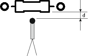
Layout diagram of a fan stop control device
On this layout, we studied the effect of air flow on the thermocouple temperature at various combinations of heater and sensor (their different relative position relative to the direction of air flow, different distance between the heater and sensor ( d )).
The air flow was regulated by partial or complete overlap of the rectifier's intake grille.
The result of the experiments was the following. The principle of a heat flow meter in its classical form proved to be of little use at a low heater temperature. The air flow of the working fan turned out to be too powerful, and the heat transfer from the heater to the sensor turned out to be inconspicuous. An increase in temperature is undesirable due to possible overheating due to contamination / dusting of the surface of the heater or sensor.
The most effective was the assessment of the degree of cooling of the heater by air flow. At the same time, a fixed power is "pumped" into the heater, which ensures heating by a fixed value above ambient temperature. In the experiments, a value of about 30 ° C was chosen.
In this case, the sensor is located in close proximity to the surface of the heater (d ≈ 1 ÷ 2 mm) and, in the absence of a flow, can freely heat up from radiation. This approach virtually eliminates the influence of the relative position of the sensor and the heater relative to the air flow of the rectifier and convection flows.
The rectifier air flow, much colder than the temperature of the heater, cools it, leading to a drop in the temperature of the sensor. As can be seen from the above description, the measurement principle differs significantly from the heat flow meter, in which the air flow increases the temperature of the sensor with heat transferred from the heater.
The experiments on the full air flow (ambient temperature was 22 ° C) and on the absent flow showed that the temperature drop of the sensor was 7 ° C and higher (the temperature difference increases with the heater power) and averaged about 10 ° C.
The experimental results are shown in the figure:
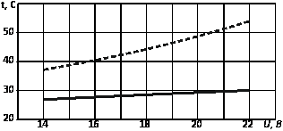
Temperature versus voltage across the heater The
dashed line shows the temperature versus voltage across the heater (0.25 W resistor with a resistance of 1 kOhm) with full air flow from the fan, and a solid one with partially blocked air intake grille of the rectifier.
As can be seen from this figure, the proposed solution allows us to record the fact of stopping the fans, as well as to quantitatively evaluate the degree of its operability to predict its failure.
Photographs of the assembled model for assessing the degree of cooling of the heater by air flow are shown below.

Simulation of a fan stop
In the absence of air movement, the thermocouple recorded a temperature of about 50 ° C.
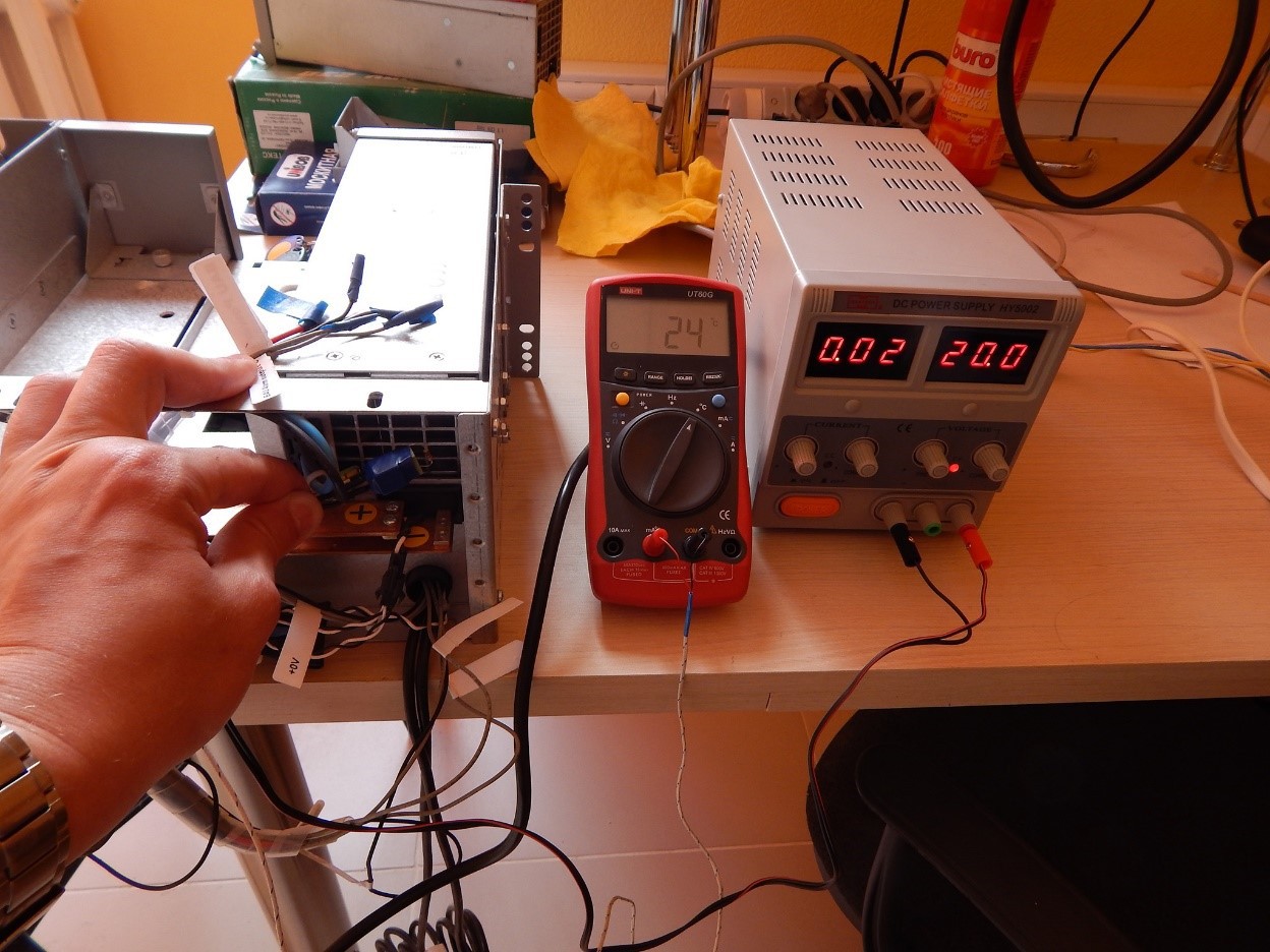
The air flow from the fan enters the sensor.
When the air flow from the fan was directed to the sensor, the temperature dropped sharply to 24 ° C.
CREATING A PROTOTYPE
The prototype of the rectifier monitor was made on the basis of the PIC16F1824 microcontroller and two MCP9700A thermal sensors. The same resistor with a power of 0.25 W was used as a heater as in the layout scheme:

Appearance of the rectifier monitor
One thermal sensor (next to the heating resistor) is used to evaluate the air flow from the fan, and the second to measure the temperature inside the rectifier.
An RS-485 driver is also installed on the board to integrate several of these monitors into a network. Using the DIP switch, the address of a specific monitor is set.
The appearance of monitors installed on a real electronic control unit is shown below:
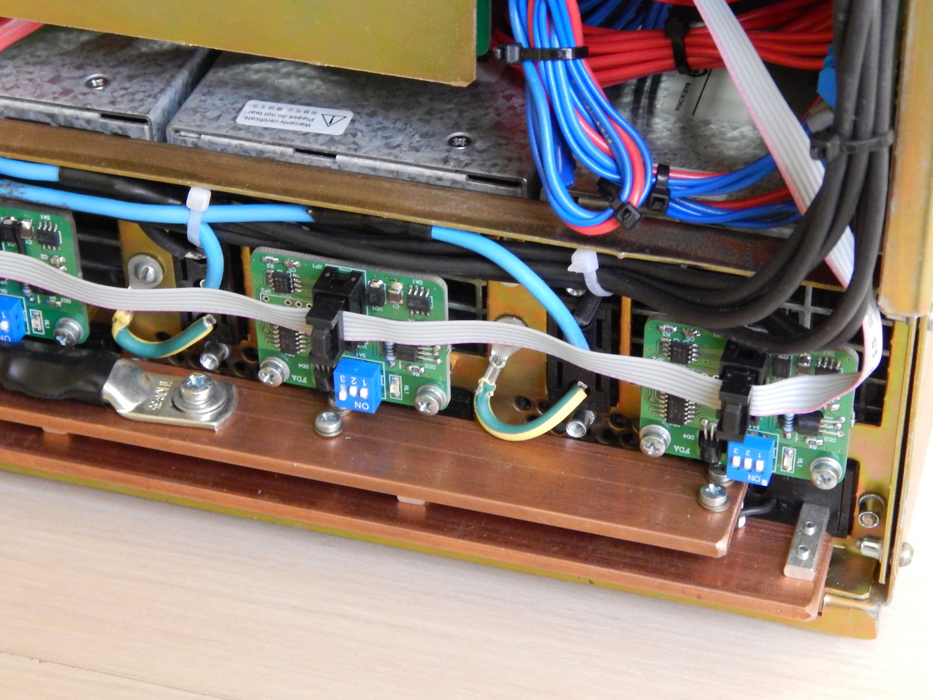
Monitors installed on an electronic control unit
Several similar devices have been tested on real ECUs. The time to determine if the fan stopped was on average about 30 seconds. In principle, it could be reduced by reducing the change in the threshold, but the customer was satisfied with this option.