Another Radio 86RK
In the distant 1989, when I was 15 years old, I, like many in those days, soldered, the then popular computer - Radio-86RK.
In 1992, he fell out of my sight, but suddenly a friend conducted a small investigation and found him. It is difficult to convey in words how pleasant and interesting it was for me to look at my brainchild. Many nuances have already been erased from memory.
The circuitry of this model, in my opinion, has been reviewed on Habré more than once, so there is little sense in repeating itself. My post is about the design features of this particular product, assembled by a simple Soviet college student, so there are a lot of photos.

On the left is a common fuse and power toggle switch.

I don’t know where I got the case, but it already had a hole in the front panel that did not match my keyboard. I closed the excess holes with linings made of wooden three-caked rulers painted with iodine and varnished. Most of the pads over the past quarter century have been lost. In the upper two LEDs are visible and above it is the “tweeter” hole. Above is an inscription indicating that the computer has 32 kilobytes of RAM. It was a volume twice the standard circuit, as can be seen in the photographs of the insides.

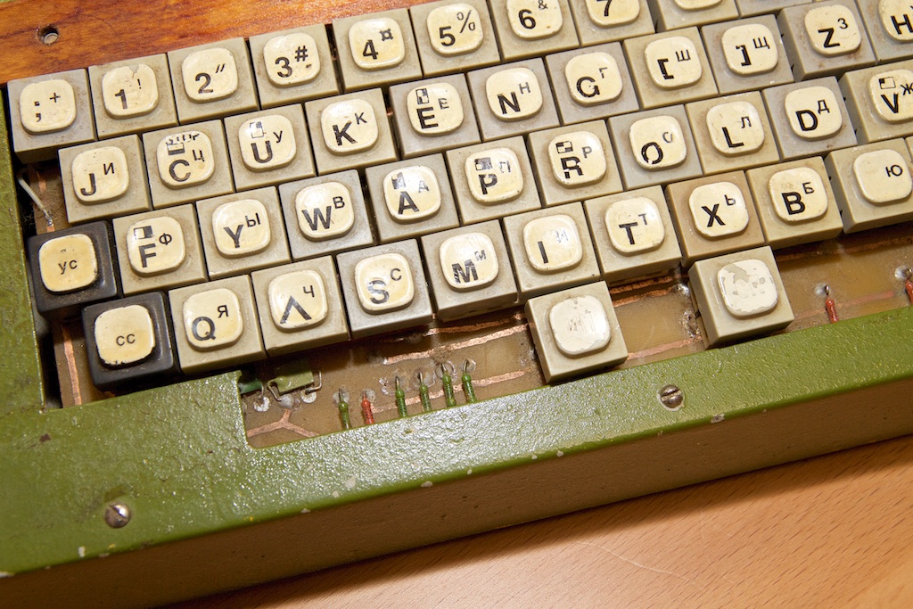
All boards except the motherboard were made by himself, grass in photographic trays with chlorine iron. The keyboard is far from QWERTY. Some keys have some extra characters. I think this is a hint of system combinations. Now, of course, I don’t remember what that means.
On the right are the connectors for the joystick, ADC (for downloading programs from the tape recorder), the video output for the monitor, and the system bus connector, which I was apparently too lazy to unsolder. I don’t know why I took it out at all. It is possible to connect and make a teletype to the radio station.

A stabilizer chip is installed on the radiator at the back. Inside, on the board, other stabilizers. It seems that the source produces three different voltages (until it was carefully understood). Pay attention to the man-made copper casing on the chip and traces of thermal paste.
Apparently, I first painted it yellow, but then changed the design to green. Probably the paint remained from the fence.

General view under the hood. Pay attention to the rope on the right, which keeps it open. Interestingly fixed motherboard. It just lies on the cambric, stretched between two screws and held by a single bar (pictured in front).


It turned out I even indicated the authorship of this monster. On the system bus - the necessary tips. Sockets for chips are cut from the connectors.

The following photo shows the center of the ADC and the speaker circuit.

The Tweeter is made from a Soviet In-ears earpiece.

The following photo shows that the increased memory is soldered directly on top of the main one. It is seen in front of the memory that a non-standard delay line has been added on the two And elements.

I am still afraid to turn it on, suspecting that the electrolytic capacitors in the source could dry out in a quarter of a century.


Under the lower casing is also interesting. You can see duplicated power lines and additional capacitors - interference filters for power.

That's all. Perhaps I will have the courage to launch this device, but that's another story.
In 1992, he fell out of my sight, but suddenly a friend conducted a small investigation and found him. It is difficult to convey in words how pleasant and interesting it was for me to look at my brainchild. Many nuances have already been erased from memory.
The circuitry of this model, in my opinion, has been reviewed on Habré more than once, so there is little sense in repeating itself. My post is about the design features of this particular product, assembled by a simple Soviet college student, so there are a lot of photos.
On the left is a common fuse and power toggle switch.
I don’t know where I got the case, but it already had a hole in the front panel that did not match my keyboard. I closed the excess holes with linings made of wooden three-caked rulers painted with iodine and varnished. Most of the pads over the past quarter century have been lost. In the upper two LEDs are visible and above it is the “tweeter” hole. Above is an inscription indicating that the computer has 32 kilobytes of RAM. It was a volume twice the standard circuit, as can be seen in the photographs of the insides.
All boards except the motherboard were made by himself, grass in photographic trays with chlorine iron. The keyboard is far from QWERTY. Some keys have some extra characters. I think this is a hint of system combinations. Now, of course, I don’t remember what that means.
On the right are the connectors for the joystick, ADC (for downloading programs from the tape recorder), the video output for the monitor, and the system bus connector, which I was apparently too lazy to unsolder. I don’t know why I took it out at all. It is possible to connect and make a teletype to the radio station.
A stabilizer chip is installed on the radiator at the back. Inside, on the board, other stabilizers. It seems that the source produces three different voltages (until it was carefully understood). Pay attention to the man-made copper casing on the chip and traces of thermal paste.
Apparently, I first painted it yellow, but then changed the design to green. Probably the paint remained from the fence.
General view under the hood. Pay attention to the rope on the right, which keeps it open. Interestingly fixed motherboard. It just lies on the cambric, stretched between two screws and held by a single bar (pictured in front).
It turned out I even indicated the authorship of this monster. On the system bus - the necessary tips. Sockets for chips are cut from the connectors.
The following photo shows the center of the ADC and the speaker circuit.
The Tweeter is made from a Soviet In-ears earpiece.
The following photo shows that the increased memory is soldered directly on top of the main one. It is seen in front of the memory that a non-standard delay line has been added on the two And elements.
I am still afraid to turn it on, suspecting that the electrolytic capacitors in the source could dry out in a quarter of a century.
Under the lower casing is also interesting. You can see duplicated power lines and additional capacitors - interference filters for power.
That's all. Perhaps I will have the courage to launch this device, but that's another story.