Development of a single-board computer from scratch. Beginner's Guide
I am developing electronics. It began relatively recently - when Atmel microcontrollers became known thanks to the Arduino platform. Then I was not particularly interested in that - at that time I already programmed them from AVR Studio, read DiHalt stories and dreamed of developing my own autopilot. 3 year, Novosibirsk, NSU - it was exciting ...
But I am watching with interest the development and growth of the embedded and portable systems industry: the appearance of RaspberryPI, the variety of SoC and motherboards based on them, smart home systems, Internet of things, smartphones with growing computing power - all this is fantastic scope for activity. The result of the observation was the desire to participate: to try yourself in the development of a simple platform, in order to study and gain experience.
Projects on microcontrollers are fed up with me - there are very few underwater rakes, it’s quite difficult to make mistakes, everything starts out of the box - neither flexibility nor complexity. With systems on a chip - SoC (System on Chip), I didn’t really care before that - unless you build the kernel and run Debian. Therefore, I decided to run a simple SoC, namely to go from a circuit to working Linux on board. Yes, in the future I will not quite correctly call the SoC processor, I hope this does not bother anyone.
I had little choice, and was determined by the complexity of manufacturing the board - only the output cases, no BGA, a maximum of four-layer design, and all because I was going to stick my handkerchief to one relatively simple working project. This also meant that in the future I would get from production a soldered board, ready for experiments.
Design
As a result of a review of the available SoCs, I opted for the iMX233 from Freescale. The output case, 454 MHz, the DDR memory controller, the interface to the SD / MMC memory card, the debug port are an excellent set for a beginner. In addition - a composite video output (“tulip”), audio input / output, SPI, I2C, UART, USB, LCD. There will be something to do at your leisure.
After reading articles on the BlackSwift platform, Qualcom Atheros AR9331 appeared in potential candidates, but was embarrassed by the lack of detailed information in the public domain. Sorry, entertaining candidate.
I was interested in the minimal configuration sufficient to run Linux on it. Accordingly, a 32 MB (256 MB) memory chip was selected for the processor (by the simple principle that we had it available). At that time, I had not yet read out in dozens of forums about the existence of difficulties with this processor, I only studied the manufacturer's recommendations for tracing and, happy as an elephant, did everything according to the recommendations.
In general, a processor (or SoC, more correctly) is more interesting from the point of view that when it is launched, design errors are much more expensive. For example, incorrect DDR memory layout can be expressed at least in subsequent read-write errors, at a maximum in the impossibility of initializing the memory at all. Processor power circuits - an error will burn the processor on first use, interfaces - loss of peripherals on these interfaces, and so on.
Therefore, it’s easier to start by studying ready-made debugging kits, for example, the official board and its documentation. I did not have a fee, but the documentation is available to everyone. In addition, it is useful to study all the instructions for use, read the forums (this is already a life experience :)) - in general, examine all available information about the victim. After studying, the mechanical work begins - draw a diagram, and then a board. Four layers, the minimum width of the conductor is 0.2mm, the gap is 0.2mm, the holes are 0.3mm.
I connected everything that can be connected painlessly - audio inputs and outputs, brought the video signal to the pads, any simple peripherals - a memory chip with I2C interface, another one with SPI, a holder for a uSD card, configuration jumpers, a debug port, and then to a free the place is all that remains. The board was small - 70x40mm, with a minimum of components. There was no space left for NAND, but I planned to start from SD / MMC. One night work.

It turned out scary. From left to right: top layer, two inside, bottom. The processor on the top layer, the memory on the bottom; for each signal conductor of the DDR interface, one vias; the lengths of the conductors are aligned, their average length is within the recommended range, the landfill between the processor and memory is almost without gaps, etc.
So, the board is designed, the documentation for it is drawn up, all this is transferred to production, and you can begin to prepare for the arrival of the boards from production. I begin to study the materials for the nuances of starting the processor, and I come across a hundred-page forums, with a description of the problems and difficulties in starting up.
It becomes uncomfortable - people have problems until the third processing of the board, the processor does not work with some memory modules, the built-in power subsystem is very unstable, the processor is very picky about power, errata (a document describing errors on the processor) answers “there’s nothing to help” we can’t ”, the software is in an open access curve, even the internal bootloader needs a patch from the manufacturer, in general, serious problems are outlined. I pump BSP (board support package) from the manufacturer - there’s a mess of hundreds of scripts and packages. The fun begins.
After a month, the boards come, and I begin the experiments. Something in the corner of the subconscious pops up related to problems in the installation industry.

Retreat
Эта система на кристалле приглянулась мне еще и тем, что несет на борту все необходимые для ее жизни регуляторы питания — как DC/DC (импульсные) так и LDO (линейные). В том числе и зарядное устройство для Li-Pol аккумулятора. Заводишь на SoC 5 вольт от USB — получаешь 1V8, 2V5, 3V3 и 4V2 на выходе. Что-то достается самому процессору, что-то уходит на память, можно аккумулятор подзарядить. Удобно. Можно сжечь все и сразу :)
Soc bringup
Get out of doubt, give food!
And no sign of life. This is good, good because without smoke. I solder the “Power” button, I look at the foot of the quartz resonator with an oscilloscope, I start it - there is generation on quartz. 24 MHz, ugly, but there. Oscilloscope probe with a divider, passive, we write to it. "Grandfather is old, he doesn't care"
The fun begins - bringup. How can this term be succinctly translated into Russian in this context? Trying to breathe life? Does not sound.
The processor has its own bootloader, which, when turned on, checks the start conditions - where and what to load. He responds to requests via the USB bus. It can be configured with jumpers on the board, or with a flashing OTP memory. If I can still solder the jumpers, then it is unlikely to reflash the unsolicited. I unsolder the jumpers, power up, and lo and behold - the first bytes of data come from the debug port! This means that the processor is satisfied with the power, its most basic nodes have started, and you can do something further. What these codes mean, I learned from the crooked header file, in the form of a PDF document, with indistinct explanations, omissions and authorship of huashan. All clear.
It’s good to work as quickly as possible with the board, it’s best to connect it by wire, and load the executable code at the click of a button. Ok, connect via USB to the computer. And nothing.
No transactions on the USB bus, even generation on quartz. Poorly. I start to think, study the board, remember all the subtle points. For example, on this board next to the processor, I put my DC / DC converter, with the expectation of supplying any consuming load, connected it to the USB 5V power bus, and did not load anything. I measure with an oscilloscope - at the input of 5 volts, at the output of 5 volts. Words from production pop up, something about the resistor. Yes, it is - there is no resistor in the feedback circuit. (- Captain, captain, the anchor has surfaced! - Hmmm, a bad omen ...)
I solder the resistor, and lo and behold! The board is detected via USB! Before that, I looked at the voltage level of the power bus - 5.1 volts, no significant interference, no ripple. But the processor knows better. After sealing the resistor, the DC / DC source also started working, so far without load, but at least it stopped interfering with the processor. Well what's next.
Next, you need to understand the initial launch of the processor and check the operation of the DDR. I start digging, and in the process of searching, I collect a set of utilities and “bootlets” - source codes that allow to initialize the power subsystems, a bunch of DDR controller-memory and prepare the system for further work. What you need is the simplest source, with an abundance of Hindu code, but most importantly, they work.
Utilities allow you to load these bootlets into the processor memory and run them for execution. Everything is so complicated, because after turning on the built-in bootloader does not know anything about external RAM, and since there is no memory, there is nowhere to load, for example, the Linux kernel. It turns out a chain of several links, where at each stage an insignificant step forward is performed.
Retreat
Для подключения к последовательным портам, для реализации всяких внутрисхемных JTAG отладчиков, программаторов и аналогичных задач в другом проекте был реализован USB-UART мост на FT2232. Двухслойный дизайн, выведены оба порта на гребенку с шагом 2 мм. В этом проекте другая история – USB-UART мост + платка сбора данных размещается в центре основной платы, и конструктив прибора предполагает ее удаление.
Т.е. в прибор плата без дырки в центре встать просто не сможет. Мне показалось нерациональным выбрасывать текстолит, и я внес свои творческие правки – собственно вышеописанный мост USB-UART(поменьше), и контроллер (MSP430FR5738) с датчиком тока, напряжения, электромеханическим реле, источником тока и термометром. Вся эта «горячая» часть гальванически изолирована от интерфейса RS485 через пару ADuM1281 и развязанный DC/DC (на плате еще не установлен). В контроллере крутится Modbus стек, т.е. десяток таких плат можно объединить в сеть, завести данные с плат в SCADA систему, и автоматизировать произвольные процессы. В частности у нас эти платки будут использоваться для испытания приборов на -40/+60 в термокамере. Налепил их на проверяемый прибор, и сиди@наблюдай как меняются токи, напряжения и температуры на ответственных узлах.
Все эти платы проектировались параллельно, поэтому я сразу заложил идентичные размеры и возможности гибкого соединения. Не зря :)

Well, I compile the sources, collect this constructor, load it, and get the first lines from the debug port! The power subsystem has started!
PowerPrep start initialize power ...
Battery Voltage = 0.65V
No battery or bad battery detected !!!. Disabling battery voltage measurements.
EMI_CTRL 0x1C084040
FRAC 0x92926152
power 0x00820710
Frac 0x92926152
start change cpu freq
hbus 0x00000003
cpu 0x00010002
I look at the sources for initializing the memory, enable the simplest test, edit the initialization procedure with the handles for my configuration of the board, start it again:
PowerPrep start initialize power ...
Battery Voltage = 1.74V
No battery or bad battery detected !!!. Disabling battery voltage measurements.
EMI_CTRL 0x1C084040
FRAC 0x92926152
power 0x00820710
Frac 0x92926152
start change cpu freq
hbus 0x00000003
cpu 0x00010002
start memory test, at 0x40000000
end memory test, at 0x41FFFFFC
Wonderful! Memory Test Passed! This is very good, now you can upload something more serious there.
U-boot
More seriously I have this U-Boot. I am familiar with this system, it seems to me quite adequate and functional. It allows you to work with peripherals - current versions work with USB, SD / MMC, Ethernet, download images from FAT / ext2 partitions, transfer control, and most importantly - blink the LED - all that is needed for happiness and more flexible debugging at the initial stage.
Therefore, without hesitation, I download the current version from the official repository, take the closest configuration, compile, assemble it with the Hindu bootlets in one file, and load it into the processor:
PowerPrep start initialize power ...
Battery Voltage = 1.74V
No battery or bad battery detected !!! Disabling battery voltage measurements.
0x1C084040 EMI_CTRL
FRAC 0x92926152
power 0x00820710
Frac 0x92926152
start change cpu freq
HBUS 0x00000003
cpu 0x00010002
start memory test, AT 0x40000000
end memory test, AT 0x41FFFFFC
the U-2015.04-rc3-00209 the Boot-ga74ef40 (Mar 16, 2015 - 12:47:34)
the CPU : Freescale i.MX23 rev1.4 at 227 MHz
BOOT: USB
DRAM: 32 MiB
MMC: MXS MMC: 0
MMC0: Bus busy timeout!
MMC0: Bus busy timeout!
MMC0: Bus busy timeout!
MMC0: Bus busy timeout!
Card did not respond to voltage select!
MMC init failed
Using default environment
In: serial
Out: serial
Err: serial
Net: Net Initialization Skipped
No ethernet found.
Hit any key to stop autoboot: 0
=>
And U-Boot has started! Great, but the board still runs by wire. It is necessary to deal with a memory card. Well, I solder the boot selection resistors, stick in the card - an error occurs in the terminal from the processor. I pull out the card - another. What a twist! ©
SD / MMC
I begin to search, searches lead to a Russian-language forum, to useful and interesting 380 pages of discussion. I'm afraid the guys still remember this SoC with a strong word.
It turns out that to boot from an SD / MMC card, it is imperative to flash OTP bits, then something else may work. In particular, it is necessary to reconfigure in the OTP Register: 24 bits of SD MBR Boot [3] - flash to one, and SD_POWER_GATE_GPIO [21:20] - select NO_GATE - the card power management is not provided in my design.
"It’s inconvenient somehow." This means that it is impossible to make a bootable memory card with which it will be possible to flash finished devices in a batch, instead you will have to connect each device and manually flash these ill-fated OTP bits. Of course, I will not use this processor in any serious project, but you should not forget about such a moment. I download the Windows utility, flash these bits, insert the memory card, battery ... The system starts and reboots cyclically. Pancake!
PowerPrep start initialize power ...
Battery Voltage = 3.75V
Boot from battery. 5v input not detected
PowerPrep start initialize power ...
Battery Voltage = 3.75V
Boot from battery. 5v input not detected
PowerPrep start initialize power ...
Battery Voltage = 3.75V
Boot from battery. 5v input not detected
...
I correct the source code of the bootlets, in particular, add additional debugging messages, and go out to the problematic section of code:
PowerPrep start initialize power ...
Battery Voltage = 3.75V
Boot from battery. 5v input not detected
Try poweron_pll
Try turnon_mem_rail
Crashes when power is applied to the DDR memory. Hm. Somewhere I already read about it. How did it work before? Okay, instability is found, we have to figure it out.
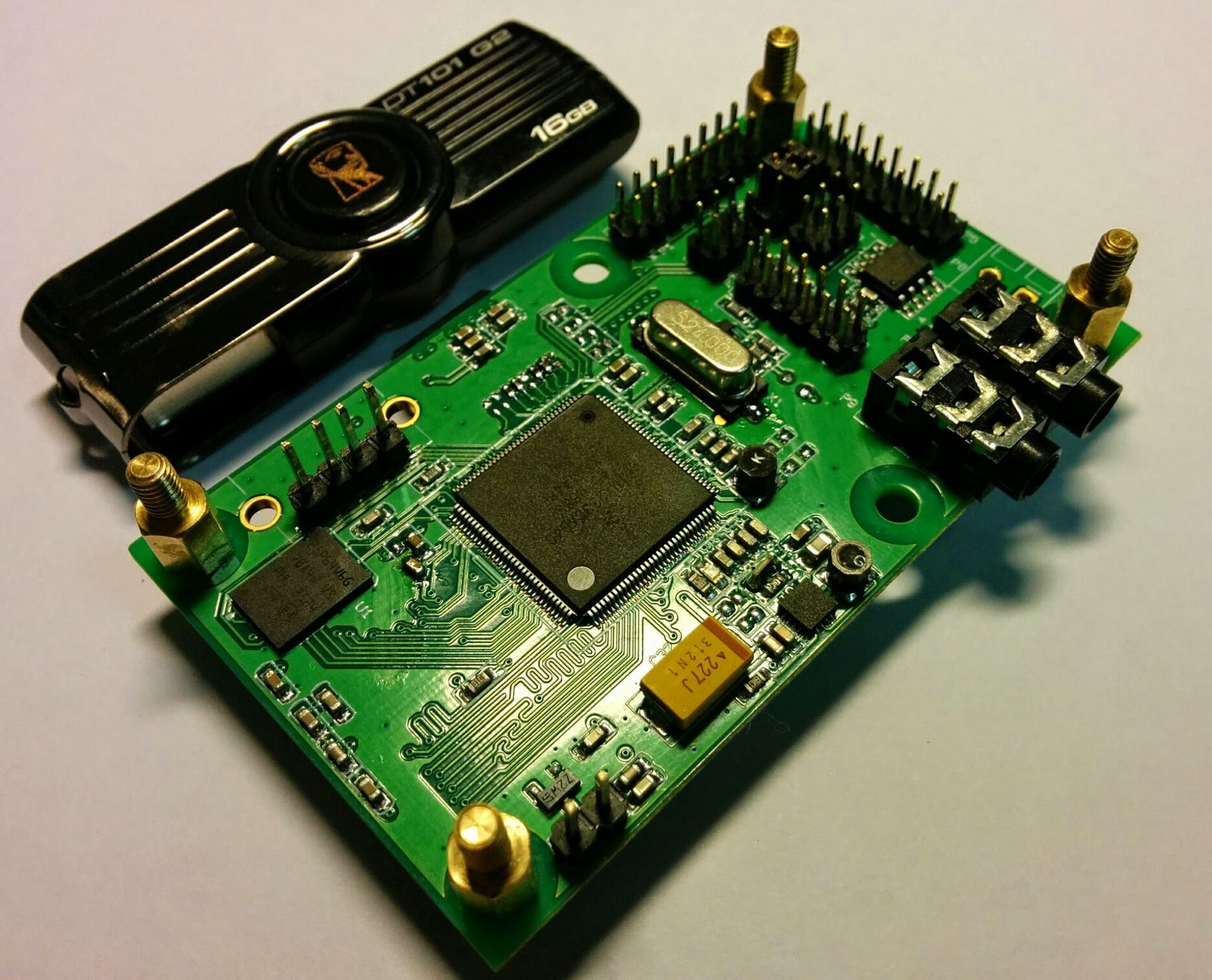
Around the memory chip are its legal decoupling capacitors, 8 pcs. 100 nF each. But at the output of the memory power supply built into the SoC, I set 2x10 uF, although the manufacturer recommended only 1uF (I read the instructions if nothing else helps, yes). Breaking, not building: I solder off one capacitor, connect the battery, and the system starts!
This capacitor is visible on the very first photo - there is dirt around it, and it is soldered with only one contact.
PowerPrep start initialize power ...
Battery Voltage = 3.75V
Boot from battery. 5v input the not detected
the Try poweron_pll
the Try turnon_mem_rail
the Try init_clock
EMI_CTRL 0x1C084040
FRAC 0x92926192
the Try init_ddr_mt46v32m16_133Mhz
power 0x00820710
Frac 0x92926192
start change cpu freq
HBUS 0x00000003
cpu 0x00010001
initcall: 3e09f908 (relocated to 40,002,908)
initcall: 3e0a013c (relocated to 4000313c)
initcall: 3e0a2ec0 (relocated to 40005ec0)
initcall: 3e0a2ea8 (relocated to 40005ea8)
initcall: 3e0a2e88 (relocated to 40005e88)
initcall: 3e0a2e68 (relocated to 40005e68)
Net: Net Initialization Skipped
No ethernet found.
initcall: 3e0a2e5c (relocated to 40005e5c)
Initial value for argc = 3
Final value for argc = 3
### main_loop entered: bootdelay = 3
### main_loop: bootcmd = "mmc dev $ {mmcdev}; if mmc rescan; then if run loadbootscript; then run bootscript; else if run loaduimage; then run mmcboot; else »
Hit any key to stop autoboot: 0
=>
=>
Hehe, it works! Ok, I will write down this fact as the cause of potential instabilities in the future, because there is one more 10uF left, which can also complicate life. Now I try with external power.
PowerPrep start initialize power ...
Battery Voltage = 3.74V 5v
source detected.Valid battery voltage detected. Booting from battery voltage source.
Mar 18 2015
07:59:13
Try poweron_pll
Try turnon_mem_rail
Try init_clock
EMI_CTRL 0x1C084040
FRAC 0x92926192
Try init_ddr_mt46v32m16_133Mhz
power 0x00820710
Frac 0x92926192
start change cpu freq
Now the freezes started. Moreover, the situation is not regular, periodically manifests itself when powered by a battery, periodically from external 5V, periodically starts and works. Again I correct the code, I turn off the processor switching to PLL, the kernel remains at 24 MHz. Everything is stable. I change the PLL divider, twist the frequency, and the board successfully starts at 320 MHz. We must try the manufacturer's recommendation - a 100 pF capacitor in a pulsed DC / DC circuit. I put a place on the printed circuit board under the capacitor. I will return to this issue later.
Linux kernel
So, at the moment there is a board starting from the memory card, and loading U-Boot. Further according to the plan, it is necessary to load the kernel.
I pump out the actual kernel source from kernel.org, unpack it and assemble the kernel in three clicks.
make ARCH = arm CROSS_COMPILE = $ {CC} mxs_defconfig
make ARCH = arm CROSS_COMPILE = $ {CC} menuconfig
make ARCH = arm CROSS_COMPILE = $ {CC} -j4 zImage modules
These three clicks
При настройке ядра надо строго указать слияние ядра+dtb
Надо включить Kernel low-level debugging functions вместе с early printk
И еще enable dynamic printk() support
И еще видеоподсистему отключить
И еще половину лишних и не очень драйверов
И еще собрать dtb — device tree blob, структуру, описывающую ядру базовые вещи — количество памяти, периферию SoC, и т.д.
И собрать все это в один файл
Boot options ---> Use appended device tree blob to zImage ----> Supplement the appended DTB with traditional ATAG information
Надо включить Kernel low-level debugging functions вместе с early printk
И еще enable dynamic printk() support
И еще видеоподсистему отключить
И еще половину лишних и не очень драйверов
И еще собрать dtb — device tree blob, структуру, описывающую ядру базовые вещи — количество памяти, периферию SoC, и т.д.
make ARCH=arm CROSS_COMPILE=${CC} imx23-olinuxino.dtb
И собрать все это в один файл
cat arch/arm/boot/zImage arch/arm/boot/dts/imx23-olinuxino.dtb > arch/arm/boot/zImage_dtb
Then you can copy the kernel to a flash.
I start it and get kernel panic. Logically, there is no root file system yet.
Debian
As the actual operating system, I choose Debian. In my opinion, an excellent distribution is simple and reliable, like a wooden stick. I take the finished assembly, unpack it on the card section, and indicate when loading the kernel where to look for its legal root.
Boot log
PowerPrep start initialize power…
Battery Voltage = 3.68V
Boot from battery. 5v input not detected
poweron_pll
turnon_mem_rail
init_clock
EMI_CTRL 0x1C084040
FRAC 0x92925E92
init_ddr_mt46v16m16_96Mhz
power 0x00820710
Frac 0x92925E92
start change cpu freq
Try now
hbus 0x00000003
cpu 0x00010001
U-Boot 2015.04-rc3-00209-ga74ef40-dirty (Mar 18 2015 — 14:26:18)
CPU: Freescale i.MX23 rev1.4 at 320 MHz
BOOT: USB
DRAM: 32 MiB
MMC: MXS MMC: 0
In: serial
Out: serial
Err: serial
Net: Net Initialization Skipped
No ethernet found.
Hit any key to stop autoboot: 0
2650994 bytes read in 906 ms (2.8 MiB/s)
Kernel image @ 0x41000000 [ 0x000000 — 0x284e60 ]
Starting kernel…
Uncompressing Linux… done, booting the kernel.
[ 0.000000] Booting Linux on physical CPU 0x0
[ 0.000000] Linux version 3.19.2 (freeman@freeman-PC) (gcc version 4.9.2 20140904 (prerelease) (crosstool-NG linaro-1.13.1-4.9-2014.09 — Linaro GCC 4.5
[ 0.000000] CPU: ARM926EJ-S [41069265] revision 5 (ARMv5TEJ), cr=0005317f
[ 0.000000] CPU: VIVT data cache, VIVT instruction cache
[ 0.000000] Machine model: i.MX23 Olinuxino Low Cost Board
[ 0.000000] Memory policy: Data cache writeback
[ 0.000000] Built 1 zonelists in Zone order, mobility grouping on. Total pages: 8128
[ 0.000000] Kernel command line: console=ttyAMA0,115200 root=/dev/mmcblk0p3 rw rootwait
[ 0.000000] PID hash table entries: 128 (order: -3, 512 bytes)
[ 0.000000] Dentry cache hash table entries: 4096 (order: 2, 16384 bytes)
[ 0.000000] Inode-cache hash table entries: 2048 (order: 1, 8192 bytes)
[ 0.000000] Memory: 18972K/32768K available (3475K kernel code, 244K rwdata, 1372K rodata, 188K init, 8096K bss, 13796K reserved, 0K cma-reserved)
[ 0.000000] Virtual kernel memory layout:
[ 0.000000] vector: 0xffff0000 — 0xffff1000 ( 4 kB)
[ 0.000000] fixmap: 0xffc00000 — 0xfff00000 (3072 kB)
[ 0.000000] vmalloc: 0xc2800000 — 0xff000000 ( 968 MB)
[ 0.000000] lowmem: 0xc0000000 — 0xc2000000 ( 32 MB)
[ 0.000000] modules: 0xbf000000 — 0xc0000000 ( 16 MB)
[ 0.000000] .text: 0xc0008000 — 0xc04c42ac (4849 kB)
[ 0.000000] .init: 0xc04c5000 — 0xc04f4000 ( 188 kB)
[ 0.000000] .data: 0xc04f4000 — 0xc0531018 ( 245 kB)
[ 0.000000] .bss: 0xc0531018 — 0xc0d19264 (8097 kB)
[ 0.000000] SLUB: HWalign=32, Order=0-3, MinObjects=0, CPUs=1, Nodes=1
[ 0.000000] NR_IRQS:16 nr_irqs:16 16
[ 0.000000] sched_clock: 32 bits at 100 Hz, resolution 10000000ns, wraps every 21474836480000000ns
[ 0.000000] Console: colour dummy device 80x30
[ 0.000000] Lock dependency validator: Copyright © 2006 Red Hat, Inc., Ingo Molnar
[ 0.000000]… MAX_LOCKDEP_SUBCLASSES: 8
[ 0.000000]… MAX_LOCK_DEPTH: 48
[ 0.000000]… MAX_LOCKDEP_KEYS: 8191
[ 0.000000]… CLASSHASH_SIZE: 4096
[ 0.000000]… MAX_LOCKDEP_ENTRIES: 32768
[ 0.000000]… MAX_LOCKDEP_CHAINS: 65536
[ 0.000000]… CHAINHASH_SIZE: 32768
[ 0.000000] memory used by lock dependency info: 5167 kB
[ 0.000000] per task-struct memory footprint: 1152 bytes
[ 0.060000] Calibrating delay loop… 159.12 BogoMIPS (lpj=795648)
[ 0.070000] pid_max: default: 32768 minimum: 301
[ 0.070000] Mount-cache hash table entries: 1024 (order: 0, 4096 bytes)
[ 0.070000] Mountpoint-cache hash table entries: 1024 (order: 0, 4096 bytes)
[ 0.080000] CPU: Testing write buffer coherency: ok
[ 0.080000] Setting up static identity map for 0x40353070 — 0x403530c8
[ 0.110000] devtmpfs: initialized
[ 0.130000] pinctrl core: initialized pinctrl subsystem
[ 0.180000] DMA: preallocated 256 KiB pool for atomic coherent allocations
[ 0.290000] Serial: AMBA PL011 UART driver
[ 0.290000] 80070000.serial: ttyAMA0 at MMIO 0x80070000 (irq = 17, base_baud = 0) is a PL011 rev2
[ 0.480000] console [ttyAMA0] enabled
[ 0.560000] mxs-dma 80004000.dma-apbh: initialized
[ 0.590000] mxs-dma 80024000.dma-apbx: initialized
[ 0.600000] SCSI subsystem initialized
[ 0.610000] pps_core: LinuxPPS API ver. 1 registered
[ 0.610000] pps_core: Software ver. 5.3.6 — Copyright 2005-2007 Rodolfo Giometti <giometti@linux.it>
[ 0.620000] Switched to clocksource mxs_timer
[ 1.130000] futex hash table entries: 256 (order: 1, 11264 bytes)
[ 1.290000] jffs2: version 2.2. (NAND) © 2001-2006 Red Hat, Inc.
[ 1.320000] Block layer SCSI generic (bsg) driver version 0.4 loaded (major 250)
[ 1.330000] io scheduler noop registered (default)
[ 1.340000] of_dma_request_slave_channel: dma-names property of node '/apb@80000000/apbx@80040000/serial@80070000' missing or empty
[ 1.360000] uart-pl011 80070000.serial: no DMA platform data
[ 1.360000] 8006c000.serial: ttyAPP0 at MMIO 0x8006c000 (irq = 146, base_baud = 1500000) is a 8006c000.serial
[ 1.380000] mxs-auart 8006c000.serial: Found APPUART 3.0.0
[ 1.410000] mousedev: PS/2 mouse device common for all mice
[ 1.430000] stmp3xxx-rtc 8005c000.rtc: rtc core: registered 8005c000.rtc as rtc0
[ 1.440000] i2c /dev entries driver
[ 1.450000] stmp3xxx_rtc_wdt stmp3xxx_rtc_wdt: initialized watchdog with heartbeat 19s
[ 1.460000] softdog: Software Watchdog Timer: 0.08 initialized. soft_noboot=0 soft_margin=60 sec soft_panic=0 (nowayout=0)
[ 1.470000] Driver 'mmcblk' needs updating — please use bus_type methods
[ 1.480000] 80010000.ssp supply vmmc not found, using dummy regulator
[ 1.540000] mxs-mmc 80010000.ssp: initialized
[ 1.630000] mmc0: host does not support reading read-only switch, assuming write-enable
[ 1.640000] stmp3xxx-rtc 8005c000.rtc: setting system clock to 1970-01-01 00:27:21 UTC (1641)
[ 1.660000] mmc0: new high speed SD card at address e624
[ 1.680000] mmcblk0: mmc0:e624 SU02G 1.84 GiB
[ 1.730000] mmcblk0: p1 p2 p3
[ 1.740000] usb0_vbus: disabling
[ 1.780000] EXT3-fs (mmcblk0p3): error: couldn't mount because of unsupported optional features (240)
[ 1.800000] EXT2-fs (mmcblk0p3): error: couldn't mount because of unsupported optional features (240)
[ 1.870000] EXT4-fs (mmcblk0p3): mounted filesystem with ordered data mode. Opts: (null)
[ 1.880000] VFS: Mounted root (ext4 filesystem) on device 179:3.
[ 1.910000] devtmpfs: mounted
[ 1.920000] Freeing unused kernel memory: 188K (c04c5000 — c04f4000)
INIT: version 2.88 booting
Using makefile-style concurrent boot in runlevel S.
Starting the hotplug events dispatcher: udevdudevd[78]: error getting socket: Function not implemented
error initializing control socketudevd[78]: error initializing udevd socket
failed!
Setting the system clock.
Activating swap...done.
[ 6.410000] EXT4-fs (mmcblk0p3): re-mounted. Opts: (null)
Checking root file system...fsck from util-linux-ng 2.17.2
rootfs: clean, 10152/115920 files, 89453/462839 blocks
done.
[ 6.870000] EXT4-fs (mmcblk0p3): re-mounted. Opts: (null)
Setting the system clock.
Cleaning up ifupdown…
Setting up networking…
Loading kernel modules...done.
Activating lvm and md swap...done.
Mounting local filesystems...done.
Activating swapfile swap...done.
Cleaning up temporary files…
Setting kernel variables ...done.
INIT: Entering runlevel: 2
Using makefile-style concurrent boot in runlevel 2.
Starting NTP server: ntpd.
Starting OpenBSD Secure Shell server: sshd.
Debian GNU/Linux 6.0 debian ttyAMA0
debian login: root
Password:
Last login: Thu Jan 1 02:00:41 EET 1970 on ttyAM0
Linux debian 3.19.2 #5 Thu Mar 19 10:58:08 EDT 2015 armv5tejl
The programs included with the Debian GNU/Linux system are free software;
the exact distribution terms for each program are described in the
individual files in /usr/share/doc/*/copyright.
Debian GNU/Linux comes with ABSOLUTELY NO WARRANTY, to the extent
permitted by applicable law.
root@debian:~#
root@debian:~# free
total used free shared buffers cached
Mem: 19160 18292 868 0 1496 9756
-/+ buffers/cache: 7040 12120
Swap: 0 0 0
root@debian:~#
root@debian:~# cat /proc/cpuinfo
processor: 0
model name: ARM926EJ-S rev 5 (v5l)
BogoMIPS: 159.12
Features: swp half fastmult edsp java
CPU implementer: 0x41
CPU architecture: 5TEJ
CPU variant: 0x0
CPU part: 0x926
CPU revision: 5
Hardware: Freescale MXS (Device Tree)
Revision: 0000
Serial: 0000000000000000
root@debian:~#
root@debian:~# df
Filesystem 1K-blocks Used Available Use% Mounted on
rootfs 1789440 295900 1384592 18% /
tmpfs 9580 0 9580 0% /lib/init/rw
udev 10240 0 10240 0% /dev
tmpfs 9580 0 9580 0% /dev/shm
tmpfs 9580 0 9580 0% /var/volatile
tmpfs 9580 0 9580 0% /media/ram
root@debian:~#
root@debian:~# mount
rootfs on / type auto (rw)
tmpfs on /lib/init/rw type tmpfs (rw,nosuid,mode=0755)
proc on /proc type proc (rw,noexec,nosuid,nodev)
sysfs on /sys type sysfs (rw,noexec,nosuid,nodev)
udev on /dev type tmpfs (rw,mode=0755)
tmpfs on /dev/shm type tmpfs (rw,nosuid,nodev)
devpts on /dev/pts type devpts (rw,noexec,nosuid,gid=5,mode=620)
tmpfs on /var/volatile type tmpfs (rw)
tmpfs on /media/ram type tmpfs (rw)
Yeah, there is work to do.
But, nevertheless, the system works, is loaded from a memory card, is located in the entire range of DDR memory, and can rightfully be called a single-board computer! This is from the circuit in the head to the implementation in the gland.
In total, design errors have not yet been detected, although there are already complaints. Well, for starters, I think that's enough.
Conclusion
This is actually just the beginning. There is still work to do - to deal with peripherals, in particular, audio and video output is interesting, test SoC at standard frequencies, and even better to disperse, measure the current consumption, check at minus and plus temperatures (stability of the DDR controller is interesting), check on demanding tasks ( for example, video transmission from a web camera via USB WIFI), and as a result make a WiFi-controlled tank with a camera and a directional microphone on the board. But not now. Now I have a business proposal :)

There are three boards I can give back. All you need to get is to voice in the comments the idea of how to apply the resulting system. The best offers will be received in a copy for free, with the hope that you will realize your idea and tell what you did. I will distribute the elephants on March 30, 2015, i.e. a week later.
This will be a feedback for me: I need to know how the system will behave in real conditions, how reliably it will show itself, what problems will arise, etc.
That's probably all, I'm waiting for your comments.
UPD: on request: the first copy goes to neochapay for the idea with a positive rating, the
second copy will go to r00tGER , the third REPISOT
“Whoever got up before, that’s slippers.”