USB microwave generator
It happens that one microwave generator is not enough at the workplace, or someone is using it, but it is very necessary to check for example a mixer (amplifier, ADC ...). And stationary microwave generators are quite large and heavy, I personally am often too lazy to transfer them and free up space on my desktop. For these reasons, two years ago I made my own small generator, the first version.

The generator is built on an HMC833 chip (or HMC830), a PLL with an integrated VCO and an HMC625 chip, and a variable gain amplifier. As a reference generator, you can use the generators GK155-P or CB3LV with a frequency of 25 ... 100 MHz. In the first version of the generator for controlling the HMC833 and HMC625, I decided to use the FT232RL chip in bit bang mode, inspired by articles about this mode on the Internet.
- Frequency range 25 ... 6000 MHz, if the chip is HMC833;
- Frequency range 25 ... 3000 MHz, if the chip is HMC830;
- Adjustment of the signal by power, 31.5 dB, in increments of 0.5 dB;
- Accuracy of frequency setting, ~ 3 Hz;
- The maximum measured signal power at a frequency of 1 GHz - 17 dBm;
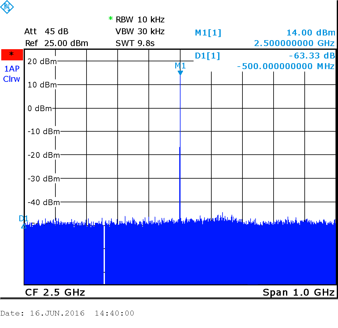
- The maximum measured signal power at a frequency of 2 GHz - 16 dBm;
- The maximum measured signal power at a frequency of 3 GHz - 12 dBm;
- Power and control from microUSB.
All other characteristics can be found in the documentation for the microcircuit used by me.
The scheme of the first version was not without drawbacks:
- firstly, as I have already said, the FT232RL chip in bit bang mode was used to control the synthesizer and amplifier using SPI. Because of this, management was slow. I first used the FT232RL chip and did not know about this feature.
- secondly, I used the components that I had available. Because of this, the generator turned out to be expensive, and some elements are difficult to get.
But in general, the generator paid off, often helping me in my work.
Two years later, I decided to get rid of these shortcomings and made a second version of the generator.
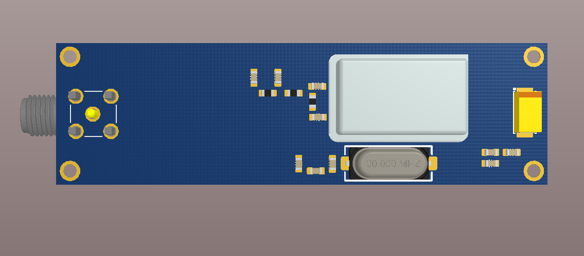
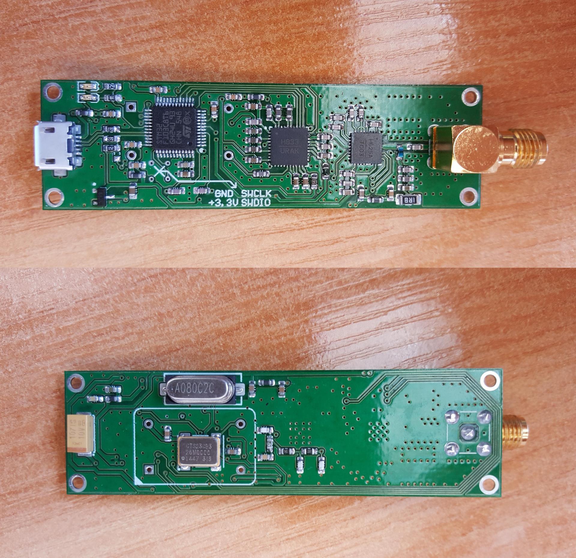
I replaced the FT232RL microcircuit with the STM32F103C8T6 microcontroller, instead of the expensive GK155-P-100 MHz generator, you can install CB3LV-3I-25M0000 (or another), well, by little things. Now all the elements for the generator can be bought from the Chinese on aliexpress, which is good news.
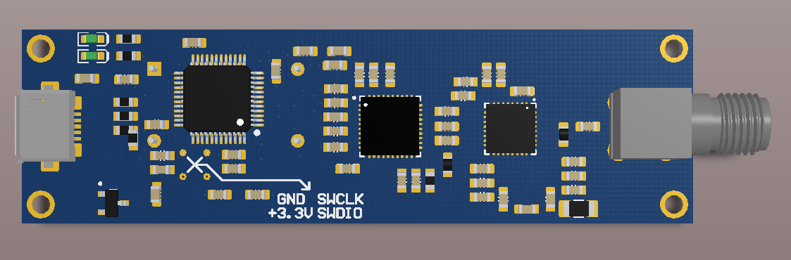
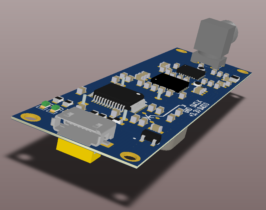
I designed the circuit board in Altium Designer, the program for STM32 was written in the IAR Embedded Workbench, the control program for the computer was written using QT, Visual Studio and the HID API library. Since the USB HID class is used, driver installation is not required.
You can assemble this USB generator yourself, for this I attach all the necessary files. Without errors, the assembled generator does not need adjustment and tuning, only firmware.
At the moment, the software is still far from the final one and has only basic settings, such as setting the frequency and gain. In the near future I plan to add GKCh modes and possibly (if possible) a pulse generator.
Now a few pictures from the R&S FSL3 spectrum analyzer and at the very end of the link to the source files. Unfortunately, the spectrum analyzer in my work is only up to 3 GHz:
The source files are here:
github.com/denruss/usb_gen_v2
github.com/denruss/usb_gen_v2_qt
github.com/denruss/usb_gen_v2_stm32
github.com/denruss/stm32_MyDfu
You can order a PCB from the link:
www.pcbway.com/project_shere_share_share .html
The st-link v2 programmer is required
0) It is advisable to erase the microcontroller with the STM32 ST-LINK Utility utility (just in case)
1) You need to download the bootloader, unpack the stm32_MyDfu.rar file from here
, flash the STM32 ST-LINK Utility utility
after that it should appear in the manager stm32 dfu device devices (I don’t remember exactly)
2) Download the usb_gen_v2_stm32_v19.dfu file from here
And flash it with the DfuSe USB device firmware upgrade utility
A little bit about the element base
The generator is built on an HMC833 chip (or HMC830), a PLL with an integrated VCO and an HMC625 chip, and a variable gain amplifier. As a reference generator, you can use the generators GK155-P or CB3LV with a frequency of 25 ... 100 MHz. In the first version of the generator for controlling the HMC833 and HMC625, I decided to use the FT232RL chip in bit bang mode, inspired by articles about this mode on the Internet.
Specifications
- Frequency range 25 ... 6000 MHz, if the chip is HMC833;
- Frequency range 25 ... 3000 MHz, if the chip is HMC830;
- Adjustment of the signal by power, 31.5 dB, in increments of 0.5 dB;
- Accuracy of frequency setting, ~ 3 Hz;
- The maximum measured signal power at a frequency of 1 GHz - 17 dBm;
- The maximum measured signal power at a frequency of 2 GHz - 16 dBm;
- The maximum measured signal power at a frequency of 3 GHz - 12 dBm;
- Power and control from microUSB.
All other characteristics can be found in the documentation for the microcircuit used by me.
A little about the shortcomings of the first version
The scheme of the first version was not without drawbacks:
- firstly, as I have already said, the FT232RL chip in bit bang mode was used to control the synthesizer and amplifier using SPI. Because of this, management was slow. I first used the FT232RL chip and did not know about this feature.
- secondly, I used the components that I had available. Because of this, the generator turned out to be expensive, and some elements are difficult to get.
But in general, the generator paid off, often helping me in my work.
Error correction
Two years later, I decided to get rid of these shortcomings and made a second version of the generator.
I replaced the FT232RL microcircuit with the STM32F103C8T6 microcontroller, instead of the expensive GK155-P-100 MHz generator, you can install CB3LV-3I-25M0000 (or another), well, by little things. Now all the elements for the generator can be bought from the Chinese on aliexpress, which is good news.
I designed the circuit board in Altium Designer, the program for STM32 was written in the IAR Embedded Workbench, the control program for the computer was written using QT, Visual Studio and the HID API library. Since the USB HID class is used, driver installation is not required.
You can assemble this USB generator yourself, for this I attach all the necessary files. Without errors, the assembled generator does not need adjustment and tuning, only firmware.
Conclusion
At the moment, the software is still far from the final one and has only basic settings, such as setting the frequency and gain. In the near future I plan to add GKCh modes and possibly (if possible) a pulse generator.
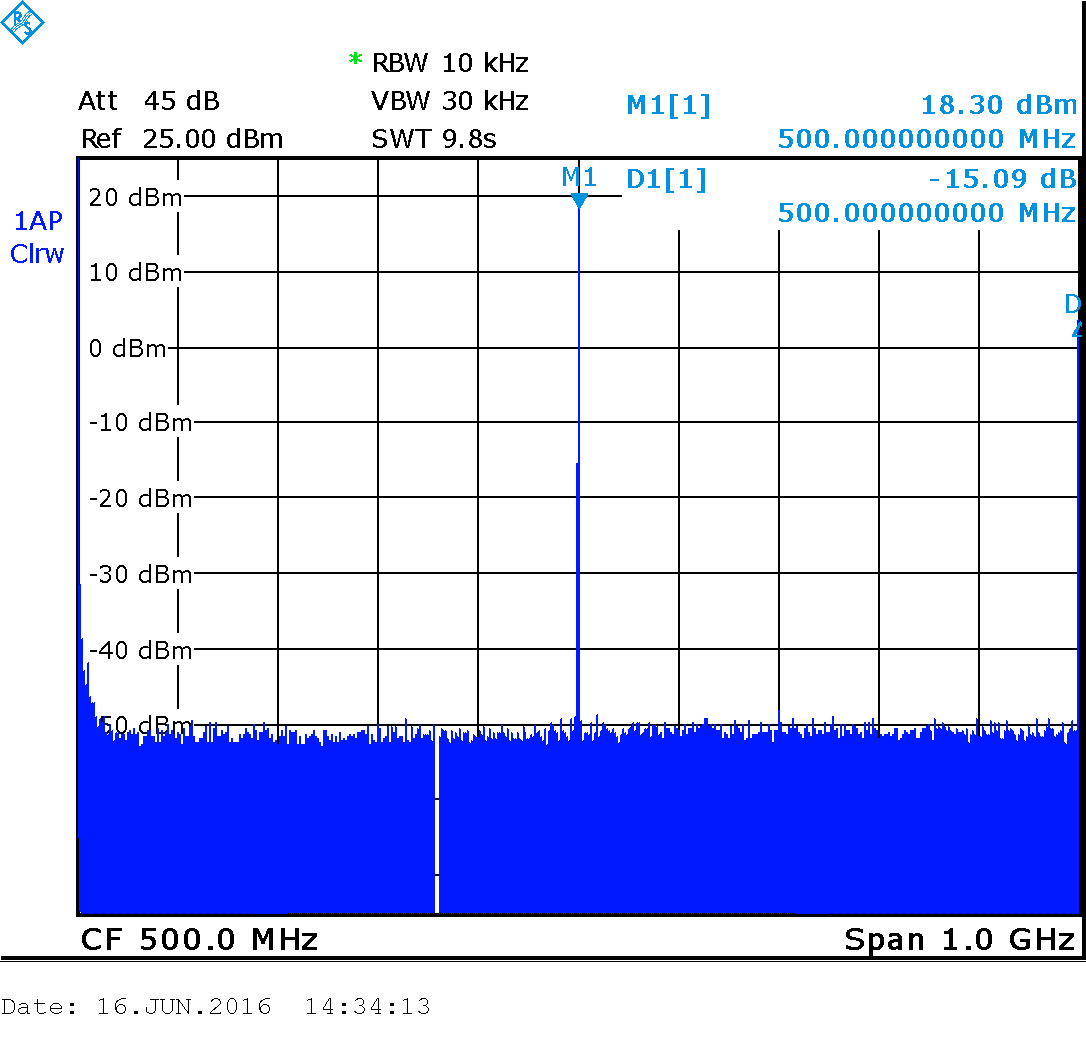
Now a few pictures from the R&S FSL3 spectrum analyzer and at the very end of the link to the source files. Unfortunately, the spectrum analyzer in my work is only up to 3 GHz:
R&S FSL3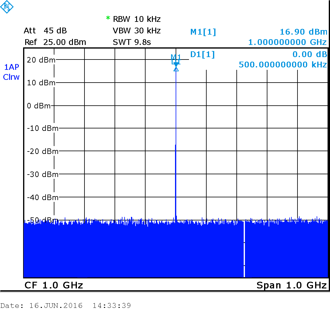


The source files are here:
github.com/denruss/usb_gen_v2
github.com/denruss/usb_gen_v2_qt
github.com/denruss/usb_gen_v2_stm32
github.com/denruss/stm32_MyDfu
You can order a PCB from the link:
www.pcbway.com/project_shere_share_share .html
Microcontroller firmware instructions
The st-link v2 programmer is required
0) It is advisable to erase the microcontroller with the STM32 ST-LINK Utility utility (just in case)
1) You need to download the bootloader, unpack the stm32_MyDfu.rar file from here
, flash the STM32 ST-LINK Utility utility
after that it should appear in the manager stm32 dfu device devices (I don’t remember exactly)
2) Download the usb_gen_v2_stm32_v19.dfu file from here
And flash it with the DfuSe USB device firmware upgrade utility