ESP8266 firmware, programming in Arduino IDE
- Tutorial
Hello again geektimes . This material is a continuation of my previous article - ESP8266 and Arduino, connection, pinout , and I must say that they are interconnected. I will not touch on topics that are already covered.
And today, I will tell you how to program the ESP8266 using the Arduino IDE , as well as flash other firmware, for example NodeMcu ... In general, this material is not limited to only one Arduino theme.
The ESP8266 theme is rather complicated. But, if you work with these Wi-Fi modules in the Arduino IDE development environment- the entry threshold drops to an acceptable level for the ordinary arduino. And not only the arduino, but any person who has a desire to bungle something on the topic of IoT (Internet of Things) , and without spending a lot of time reading documentation for the chip and learning the API for these modules.
This video completely duplicates the material presented in the article below.
Well, we already know how to connect the ESP8266 and put it into programming mode, now let's move on to something more useful.
I will say right away - once having programmed the module in the development environment of the arduino, we will remove the native firmware and we will lose the ability to work with the module using AT commands. Personally, this is not cold / hot for me, but if someone needs it, closer to the end of the article I will show how to flash the firmware back into the module, well, or some kind of bootloader like NodeMcu.
To start, on off.sayte download the latest version of the Arduino IDE, at the moment it is 1.6.7. Older versions of type 1.0.5. they don’t fit, because they do not have the necessary functionality, and dancing with a tambourine does not interest us, do they?
We start the development environment and then go to File / Settings:
Insert the link in the "Additional links for the Board Manager:" field and click "OK".
I took this link on the project page of the Arduino core for ESP8266 WiFi chip .
Then we go Tools / Board: /

Board manager ...: A window appears for the board manager, scroll to the bottom, and if everything is done correctly, we will see something like this:

Click on the inscription " esp8266 by ESP8266 Community " after of this, we got the "Installation" button, select the version you need, I take the latest, today it is 2.1.0. and install it. The development environment downloads the files it needs (about 150 megabytes) and opposite the inscription " esp8266 by ESP8266 Community " appears "INSTALLED" that is installed:
Scroll down the list of boards and see that we have a lot of different ESPs in the list, take the "Generic ESP8266 Module":
Go to the "Tools" and select the desired COM port (I have COM32) Arduino or USB UART converter , then set Upload Speed : “115200”:

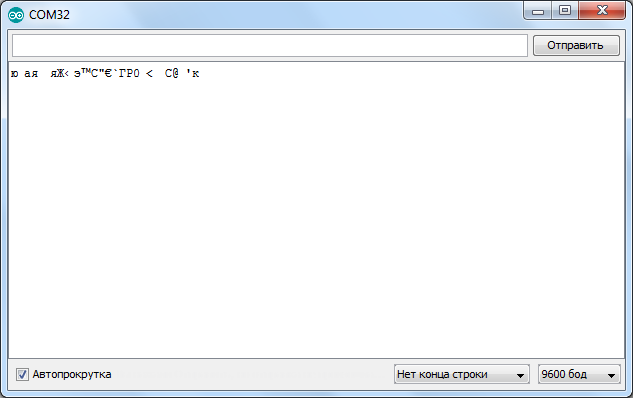
Next, open the console in the Arduino IDE, apply power to the module, if everything was done correctly, we will see something like that:
Set the speed to 74880 and “NL & CR” and again turn off and turn on the power and he will answer something which debug information:
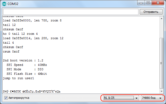
Note 74880 - not the basic rate of ESP8266, he simply just on it sends debugging Institute deformations of. If the module does not send anything to the console, then maybe something is connected incorrectly.
By default, the speed should be 115200, but in some cases there may be 9600 and others ... So try picking it up.

After selecting the desired speed, send the module "AT" and he should answer that everything is "OK". The AT + GMR command displays information about the firmware.
Before you start flashing the ESP8266 in the Arduino IDE, I advise you to read the article to the end.
Now let's try flashing the ESP8266 through the Arduino IDE. We translate the module into programming mode (I wrote how to do this in the previous article ).
Let's sew a blinker with a regular LED:
Blinked? So everything is done correctly. Where did I get that the LED is connected to the first pin? In the previous article there is a picture with the pinout of different modules , and there is port marking, when using the Arduino bootloader (pins are marked in pink).

Blinking the LED is certainly good, but it would be necessary to shut down some web server or start controlling the LED using at least the buttons in the browser, right? But I’ll tell you about this some other time.
And now how to flash back native firmware , and how to flash the module with third-party bootloaders. For ESP8266 there is such a program as NodeMCU Flasher , which was originally intended for flashing the NodeMCU bootloader. But as it turned out, it perfectly flashes other firmware as well.
I will attach an archive with this program and firmware to the article for convenience, but here you can always download the new version of NodeMCU Flasher.
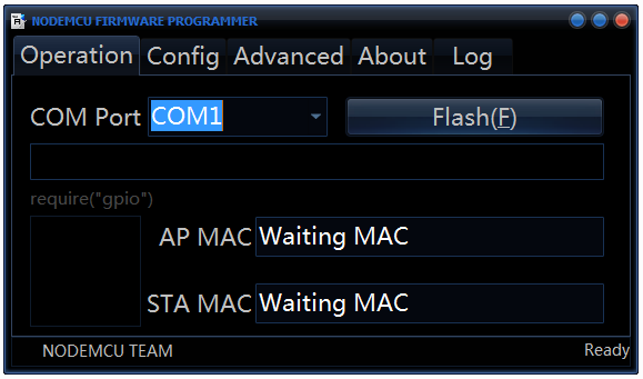
In the “nodemcu-flasher-master” folder there are 2 Win64 and Win32 folders, and depending on what bit depth on your OS, select the one you need. Next, in the Release folder, run “ESP8266Flasher.exe” and see the program interface:
Select the desired COM port and go to the “Config” tab, remove the little cross near “INTERNAL: // NODEMCU” and put it one point below, as in the screenshot:
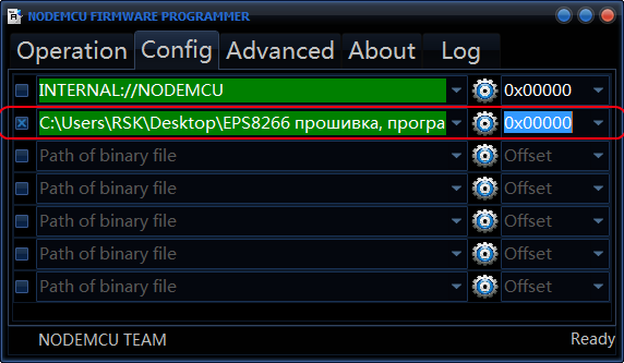
( If you want to flash the NodeMCU bootloader, remove the little cross where it was not, and put it where it was, that is, near “INTERNAL: // NODEMCU”).
Then click on the gear and select where our firmware is located, the firmware is usually in * .bin format (in the attached archive it is “v0.9.5.2 AT Firmware.bin” which lies in the main folder), and also select “0x00000” as and higher.
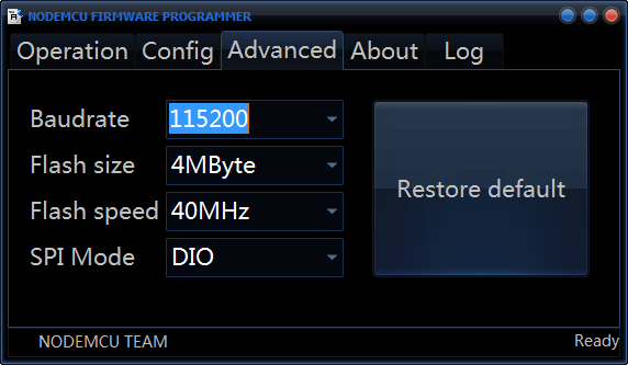
Next we go to the “Advanced” tab and change the speed there to 115200, it is this speed that will be the main one and the module will respond to AT-commands in case of corresponding firmware.
We return again to the “Operation” tab, put the module into programming mode and press “Flash”:
That's it, the module started to flash, after flashing, do not forget to restart the module and voila, it is flashed with the firmware we need.

We check with the AT-command “AT + GMR” whether we did everything right:

As you can see, everything went fine.
References:
Archive with NodeMCU Flasher, firmware and code for Arduino IDE ;
ESP8266 and Arduino, connection, pinout ;
The latest version of the Arduino IDE is always here ;
NodeMCU Flasher ;
Russian-speaking community on ESP8266 ;
Many different firmware for ESP8266 ;
All my publications on geektimes .
By Sergey Sharekin, aka Mr Podelkin.
And today, I will tell you how to program the ESP8266 using the Arduino IDE , as well as flash other firmware, for example NodeMcu ... In general, this material is not limited to only one Arduino theme.
The ESP8266 theme is rather complicated. But, if you work with these Wi-Fi modules in the Arduino IDE development environment- the entry threshold drops to an acceptable level for the ordinary arduino. And not only the arduino, but any person who has a desire to bungle something on the topic of IoT (Internet of Things) , and without spending a lot of time reading documentation for the chip and learning the API for these modules.
This video completely duplicates the material presented in the article below.
Well, we already know how to connect the ESP8266 and put it into programming mode, now let's move on to something more useful.
I will say right away - once having programmed the module in the development environment of the arduino, we will remove the native firmware and we will lose the ability to work with the module using AT commands. Personally, this is not cold / hot for me, but if someone needs it, closer to the end of the article I will show how to flash the firmware back into the module, well, or some kind of bootloader like NodeMcu.
To start, on off.sayte download the latest version of the Arduino IDE, at the moment it is 1.6.7. Older versions of type 1.0.5. they don’t fit, because they do not have the necessary functionality, and dancing with a tambourine does not interest us, do they?
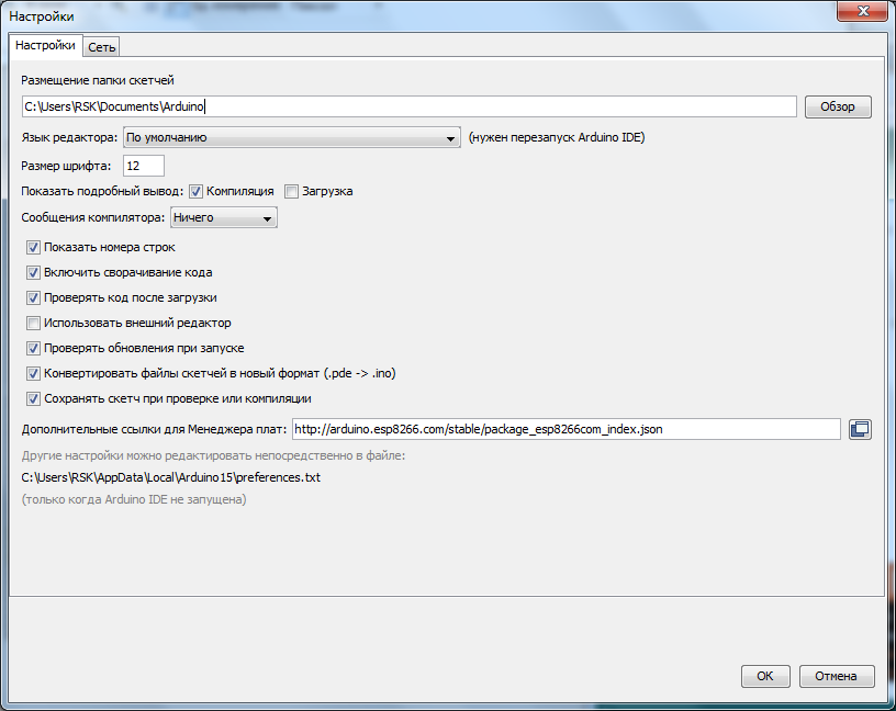
We start the development environment and then go to File / Settings:
Insert the link in the "Additional links for the Board Manager:" field and click "OK".
http://arduino.esp8266.com/stable/package_esp8266com_index.jsonI took this link on the project page of the Arduino core for ESP8266 WiFi chip .
Then we go Tools / Board: /
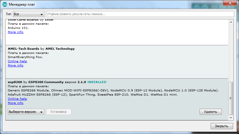
Board manager ...: A window appears for the board manager, scroll to the bottom, and if everything is done correctly, we will see something like this:
Click on the inscription " esp8266 by ESP8266 Community " after of this, we got the "Installation" button, select the version you need, I take the latest, today it is 2.1.0. and install it. The development environment downloads the files it needs (about 150 megabytes) and opposite the inscription " esp8266 by ESP8266 Community " appears "INSTALLED" that is installed:
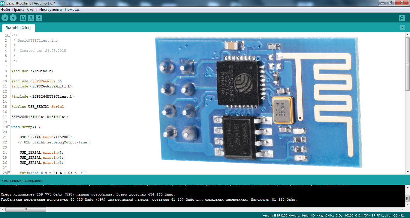
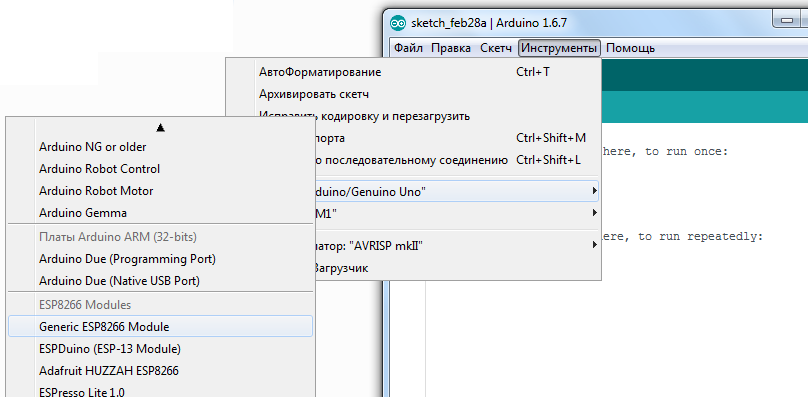
Scroll down the list of boards and see that we have a lot of different ESPs in the list, take the "Generic ESP8266 Module":
Go to the "Tools" and select the desired COM port (I have COM32) Arduino or USB UART converter , then set Upload Speed : “115200”:
Next, open the console in the Arduino IDE, apply power to the module, if everything was done correctly, we will see something like that:
Set the speed to 74880 and “NL & CR” and again turn off and turn on the power and he will answer something which debug information:
Note 74880 - not the basic rate of ESP8266, he simply just on it sends debugging Institute deformations of. If the module does not send anything to the console, then maybe something is connected incorrectly.
By default, the speed should be 115200, but in some cases there may be 9600 and others ... So try picking it up.
After selecting the desired speed, send the module "AT" and he should answer that everything is "OK". The AT + GMR command displays information about the firmware.
Before you start flashing the ESP8266 in the Arduino IDE, I advise you to read the article to the end.
Now let's try flashing the ESP8266 through the Arduino IDE. We translate the module into programming mode (I wrote how to do this in the previous article ).
Let's sew a blinker with a regular LED:
// By MrПоделкинЦ youtube.com/RazniePodelki
// special to geektimes.ru/post/271754/
#define TXD 1 // GPIO1/TXD01
void setup() {
  pinMode(TXD, OUTPUT);
}
void loop() {
  digitalWrite(TXD, HIGH);
  delay(1000);
  digitalWrite(TXD, LOW);
  delay(1000);
}
Blinked? So everything is done correctly. Where did I get that the LED is connected to the first pin? In the previous article there is a picture with the pinout of different modules , and there is port marking, when using the Arduino bootloader (pins are marked in pink).
Blinking the LED is certainly good, but it would be necessary to shut down some web server or start controlling the LED using at least the buttons in the browser, right? But I’ll tell you about this some other time.
And now how to flash back native firmware , and how to flash the module with third-party bootloaders. For ESP8266 there is such a program as NodeMCU Flasher , which was originally intended for flashing the NodeMCU bootloader. But as it turned out, it perfectly flashes other firmware as well.
I will attach an archive with this program and firmware to the article for convenience, but here you can always download the new version of NodeMCU Flasher.
In the “nodemcu-flasher-master” folder there are 2 Win64 and Win32 folders, and depending on what bit depth on your OS, select the one you need. Next, in the Release folder, run “ESP8266Flasher.exe” and see the program interface:
Select the desired COM port and go to the “Config” tab, remove the little cross near “INTERNAL: // NODEMCU” and put it one point below, as in the screenshot:
( If you want to flash the NodeMCU bootloader, remove the little cross where it was not, and put it where it was, that is, near “INTERNAL: // NODEMCU”).
Then click on the gear and select where our firmware is located, the firmware is usually in * .bin format (in the attached archive it is “v0.9.5.2 AT Firmware.bin” which lies in the main folder), and also select “0x00000” as and higher.
Next we go to the “Advanced” tab and change the speed there to 115200, it is this speed that will be the main one and the module will respond to AT-commands in case of corresponding firmware.
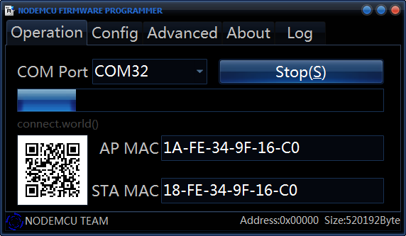
We return again to the “Operation” tab, put the module into programming mode and press “Flash”:
That's it, the module started to flash, after flashing, do not forget to restart the module and voila, it is flashed with the firmware we need.
We check with the AT-command “AT + GMR” whether we did everything right:
As you can see, everything went fine.
References:
Archive with NodeMCU Flasher, firmware and code for Arduino IDE ;
ESP8266 and Arduino, connection, pinout ;
The latest version of the Arduino IDE is always here ;
NodeMCU Flasher ;
Russian-speaking community on ESP8266 ;
Many different firmware for ESP8266 ;
All my publications on geektimes .
By Sergey Sharekin, aka Mr Podelkin.
PS
A board based on esp32 is already on its way:

http://www.pighixxx.com/test/2015/12/esp32-pinout/
Which is much cooler than esp8266, so we will soon see a boom, I think, of IoT themes (Internet of things ) .
http://www.pighixxx.com/test/2015/12/esp32-pinout/
Which is much cooler than esp8266, so we will soon see a boom, I think, of IoT themes (Internet of things ) .