SNR-S2985G-24T-UPS - Doomsday Switch
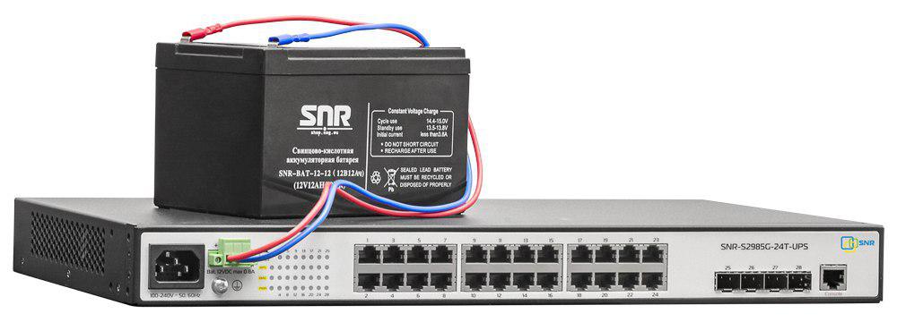
Today we decided to better introduce blog readers to the new gigabit Ethernet switch - SNR-S2985G-24T-UPS . A key feature of the model is the built-in battery charge and control unit, which allows you to organize uninterrupted power supply of the device by simply connecting a 12V battery to it, without any additional devices.
Otherwise, the SNR-S2985G-24T-UPS switch is identical to the popular SNR-S2985G-24T. The firmware, configuration, and MIB for these models are exactly the same.
For those who are not familiar with the SNR-S2985G gigabit switches or the similar SNR-S2965 series, we suggest that you familiarize yourself with this review .
We also give the technical specifications of SNR-S2985G-24T-UPS:
Specifications
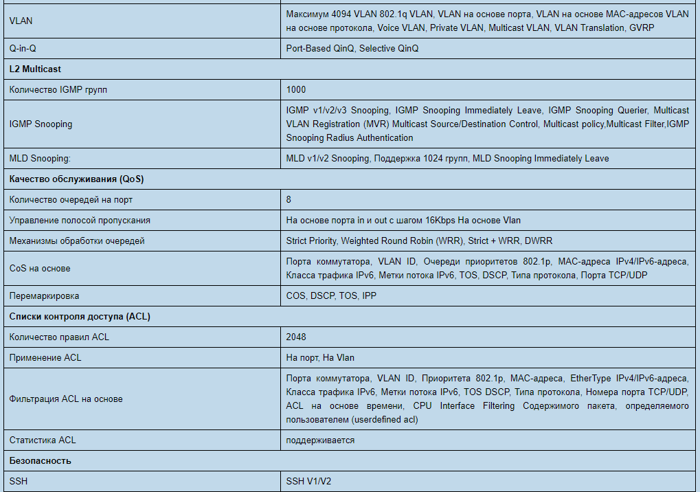
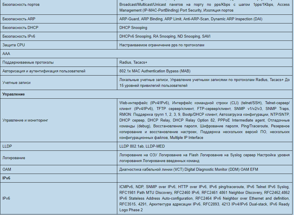
As you can see, SNR-S2985G-24T-UPS has all the necessary functionality for use at the access level both in the networks of telecom operators and in corporate LANs.
Before starting testing, we will examine the differences between this solution with redundant power supply directly from the standard “switch + UPS” circuit. And try to evaluate the benefits.

Scheme of operation of a conventional UPS The
above is a diagram of the operation of a conventional UPS. When running on battery power, the voltage passes through the inverter, where it is converted from 12V DC to 220V AC and then fed to the switch power supply, which performs the inverse conversion: 220V AC -> 12V DC. Naturally, these two processes proceed with an efficiency of less than 100%, and part of the energy stored in the battery is spent on useless heating of the UPS and the switch power supply, reducing battery life.
When the switch board is powered directly from a 12V source, there are no unnecessary conversions, and the entire battery charge is consumed as intended. Thus, using the same battery, the battery life of the switch will significantly increase. In this case, the system will take up less space.
Take a look inside.

The SNR-S2985G-24T-UPS circuit is slightly different from other models.
We pay attention to the implementation of the UPS. The SNR-S2985G-24T-UPS circuit is somewhat different from other models, where the switch power supply is combined with a battery charge controller. There is a separate board (1) responsible for working with the battery, and an independent power supply (2).
Thus, these two components are independent, and if one of them fails, the second will work. The power supply unit delivers direct current to the board in which the following functionality is implemented:
- A two-stage battery charge, first with a current limit and then with a voltage limit;
- Battery shutdown when the voltage drops below 10.8V in order to protect the battery from deep discharge;
- Cold start i.e. starting the switch from the battery in the absence of the main AC power supply (battery voltage should be at least 12.5V);
- Reverse polarity protection: if the battery is connected incorrectly, the fuse on the board will burn, while the switch will continue to operate from normal power;
- Overvoltage and short circuit protection on the terminals for connecting the battery;
- Alarm for the presence of AC-power and voltage level on the battery.
When developing the SNR-S2985G-24T-UPS, the temperature regime inside the case was taken into account - with passive cooling of the switch, the power should not exceed 30W. Therefore, the battery charge is produced by a current of about 0.8A, which is optimal for charging batteries with a capacity of 5-12Ah.
Let's get started with the switch.
One of the innovations of the SNR-S2985G-24T-UPS is the presence of voltage monitoring at the battery terminals. The value can be displayed either through the command `show rps-power-voltage`,
SNR-S2985G-24T-UPS # sh rps-power-voltage
Device rps voltage: 12.9V
or by SNMP using OID 1.3.6.1.4.1.40418.7.100.1 .101
snmpget -v2c -c public 172.31.254.250 iso.3.6.1.4.1.40418.7.100.1.101
iso.3.6.1.4.1.40418.7.100.1.101 = INTEGER: 129
(returns voltage in volts multiplied by 10) It
is also possible to find out which power supply the switch is currently using from the CLI, using the show power status command, or SNMP using OID 1.3.6.1.4.1.40418.7.100.1. 23.2 (in the presence of AC power, “1” is returned, in the absence of “2”).
Set up the switch for the test:
Turn on the SNMP agent, set up the community and enable power monitoring:
snmp-server enable // Turn on the SNMP server
snmp-server securityip disable // Allow access to SNMP for all IP
snmp-server host 192.168.188.2 v2c public / / Specify host to send trap
snmp-server community rw 0 public // Configure SNMP community
snmp-server enable traps // Enable sending SNMP traps
rps-power monitor on // Turn on AC power monitoring
The switch will be managed in Vlan 3999, create it:
vlan 3999
name management
and L3 interface for management:
interface Vlan3999
description Management_Interface
ip address 172.31.254.250 255.255.255.0
Set the default gateway:
ip default-gateway 172.31.254.1
And enable vlan on the port in trunk mode:
Interface Ethernet1 /
0/24 switchport mode trunk
switchport trunk allowed vlan 3999
Test the switch with a battery of different capacities:
We load the switch, connect the battery and turn off the AC power. A log about the transition to backup power appears in the logs and the corresponding SNMP trap is sent.
We draw a graph of the voltage on the battery using Cacti:
SNR-BAT-12-5

SNR-BAT-12-12

At the time of AC power off, the graph shows a voltage drop from 13.2V to 12.5-12.6V. Then, as the battery discharges, the voltage gradually drops until it reaches 10.8V and the switch turns off.
As you can see, the switch worked for 3 hours from the battery 5Ah and about 8 hours 15 minutes from the battery 12Ah. If necessary, you can replace the battery with a charged one or use a more capacious battery.
For comparison, the switch was powered by an inexpensive UPS with a built-in 7.2Ah battery; the switch operating time after turning off the AC power was less than 2.5 hours, which, in comparison with previous tests, confirms the effectiveness of the built-in solution.
Compare the financial component: The
retail price of the SNR-S2985G-24T-UPS switchboard is $ 225 + SNR-BAT-12-12 battery $ 23.5 = $ 248.5
A regular SNR-S2985G-24T retail will cost $ 199 + + inexpensive UPS 600VA will cost around $ 40, totaling $ 240
At a slightly higher price, the SNR-S2985G-24T-UPS has built-in monitoring, the ability to quickly replace batteries and longer battery life. When trying to achieve the described advantages with an external UPS, the cost of the solution will increase by 1.5-2 times.
As a result, SNR-S2985G-24T-UPS is a very profitable and efficient solution for organizing access nodes with the possibility of autonomous operation in limited conditions.
By the way, if you catch the spring campaign , you can save about half the 12Ah battery.