Possible explanation of EmDrive test results
- Transfer
This is just a comment on Reddit. But it seemed to me very interesting, and I did not see any references in Russian-language discussions. Paragraphs marked TL; DR are skipped.
Yes. Many. But we will focus on one of them: in my reading of the article, the data very clearly show that the displacement measured by the authors is caused by thermal expansion, and not by the draft created by the cavity. Of course, I myself did not work with the device, and therefore I can not say this with absolute certainty, but I am convinced, and I believe that you should also be.
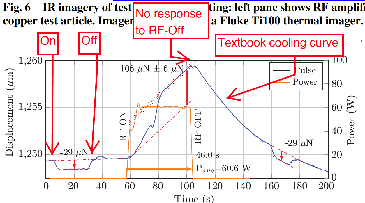
The whole point is in this graph from an article that I marked out [Translator's note: in the text of the label in English so that it can be compared]. Pay attention to the calibration pulse, the blue section between “On” and “Off”. It shows how the balancer reacts to the applied force. Pay particular attention to how quickly it returns to its original position after the end of the impulse. See how it bounces when power disappears? Here is a good experiment: they used a well-known force and showed a reaction.
Now let's look at the radio frequency pulse that is used to power EmDrive (the golden line in that figure). The authors are focusing on the beginning of this impulse, and I would like you to look at its end, which is labeled “No response to RF-Off”. See how the spring does not immediately return to its original position? Yes, the trail begins to fall, but too slowly to return the spring. Instead, it is very likely that the impulse has heated something and after its end it slowly cools. Graph directly from the textbook :
So, instead of the “new physical effect”, a simple explanation is that the pulse heats the equipment and changes the balance position of the balance. I must say that this is mentioned in their list of possible errors, and they are trying to reject this explanation, but the graphs show everything. Almost everyone does not have the quick return that should be.
Let us look at their attempt to reject this explanation and see that it only confirms it more strongly. They write that the system is configured to respond slowly (although fast or slow, this reaction rate should be the same for calibration and for the working pulse). In the earlier “split configuration”, it was faster, and Figure 12 from the article is an example of this. Let's look at him.
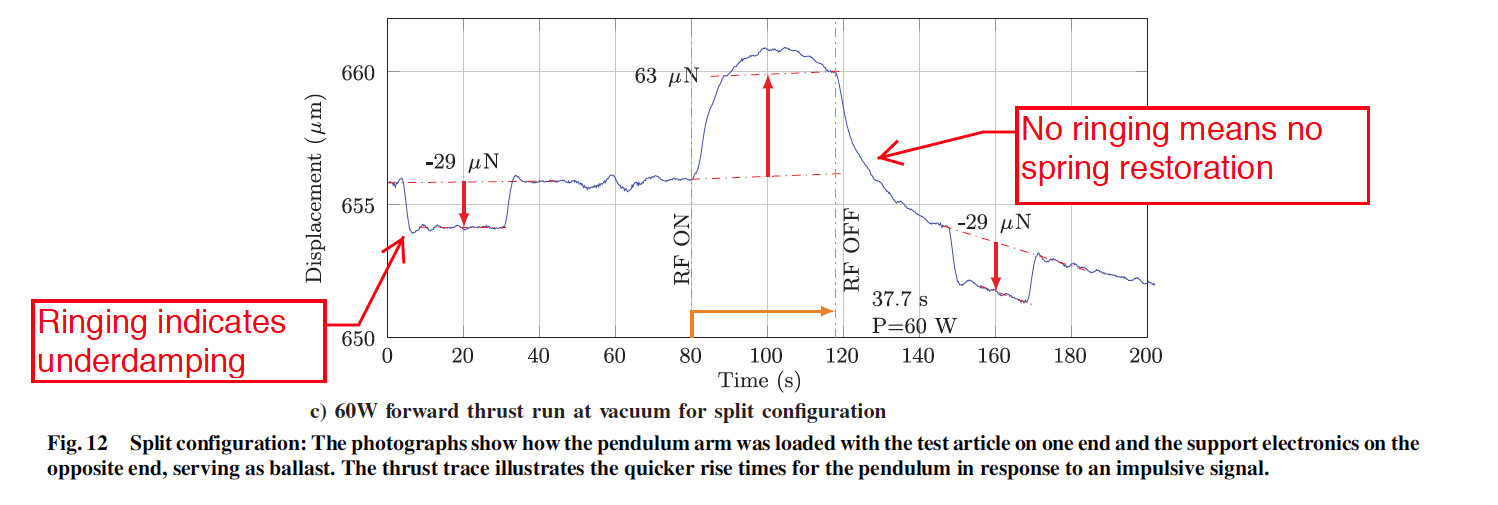
See the “ringing" (damped oscillations) at both ends of the calibration pulse (marked "Ringing indicates underdamping")? It shows that the system is under-damped. This is good - as an experimenter, you prefer a quick reaction and are willing to pay a small ripple for it. Now look at the working impulse, or rather, at its end. No ringing! This is absolutely decisive evidence. This graph alone is enough to throw away the whole experiment. The absence of ringing completely eliminates the return of the spring system to equilibrium. That is, when EmDrive is on, it does not stretch the spring. Their experiment strictly proved that EmDrive does not create traction!
Figure 12 is decisive proof that whatever moves when starting EmDrive is not a system designed to measure traction. They measure not what they think.
A few recent comments. First, White should publish the full details of the experiment. I was accused of being too superficial. If we had the source data, we could make accurate calculations, create IPython notebooks, everyone could see the analysis and discuss it quantitatively, not qualitatively. There is little data in the article, so the problem is not on my side. That would be good for everyone.
Secondly, here is a short list of improvements that I would suggest to anyone who wants to reproduce the experiment. They will directly refute this explanation. [Translator's Note: The translation of the items after the first is based on the options proposed by the Fullmoon commentator .]
NASA published the article "Measurement of Impulsive Thrust from a Closed Radio-Frequency Cavity in Vacuum" in a peer-reviewed journal. Are there any serious flaws in it?
Yes. Many. But we will focus on one of them: in my reading of the article, the data very clearly show that the displacement measured by the authors is caused by thermal expansion, and not by the draft created by the cavity. Of course, I myself did not work with the device, and therefore I can not say this with absolute certainty, but I am convinced, and I believe that you should also be.
The whole point is in this graph from an article that I marked out [Translator's note: in the text of the label in English so that it can be compared]. Pay attention to the calibration pulse, the blue section between “On” and “Off”. It shows how the balancer reacts to the applied force. Pay particular attention to how quickly it returns to its original position after the end of the impulse. See how it bounces when power disappears? Here is a good experiment: they used a well-known force and showed a reaction.
Now let's look at the radio frequency pulse that is used to power EmDrive (the golden line in that figure). The authors are focusing on the beginning of this impulse, and I would like you to look at its end, which is labeled “No response to RF-Off”. See how the spring does not immediately return to its original position? Yes, the trail begins to fall, but too slowly to return the spring. Instead, it is very likely that the impulse has heated something and after its end it slowly cools. Graph directly from the textbook :
So, instead of the “new physical effect”, a simple explanation is that the pulse heats the equipment and changes the balance position of the balance. I must say that this is mentioned in their list of possible errors, and they are trying to reject this explanation, but the graphs show everything. Almost everyone does not have the quick return that should be.
Let us look at their attempt to reject this explanation and see that it only confirms it more strongly. They write that the system is configured to respond slowly (although fast or slow, this reaction rate should be the same for calibration and for the working pulse). In the earlier “split configuration”, it was faster, and Figure 12 from the article is an example of this. Let's look at him.
See the “ringing" (damped oscillations) at both ends of the calibration pulse (marked "Ringing indicates underdamping")? It shows that the system is under-damped. This is good - as an experimenter, you prefer a quick reaction and are willing to pay a small ripple for it. Now look at the working impulse, or rather, at its end. No ringing! This is absolutely decisive evidence. This graph alone is enough to throw away the whole experiment. The absence of ringing completely eliminates the return of the spring system to equilibrium. That is, when EmDrive is on, it does not stretch the spring. Their experiment strictly proved that EmDrive does not create traction!
Figure 12 is decisive proof that whatever moves when starting EmDrive is not a system designed to measure traction. They measure not what they think.
A few recent comments. First, White should publish the full details of the experiment. I was accused of being too superficial. If we had the source data, we could make accurate calculations, create IPython notebooks, everyone could see the analysis and discuss it quantitatively, not qualitatively. There is little data in the article, so the problem is not on my side. That would be good for everyone.
Secondly, here is a short list of improvements that I would suggest to anyone who wants to reproduce the experiment. They will directly refute this explanation. [Translator's Note: The translation of the items after the first is based on the options proposed by the Fullmoon commentator .]
- Take temperature data in real time. Place sensors where possible. Thermocouples are very light and cheap. This will quantify thermal expansion.
- Use a different type of suspension since the current one can mix vertical and horizontal movements.
- Stabilize the oscillator frequency with feedback ( Pound – Drever – Hall method )
- To reduce temperature differences, do not turn off the generator, but switch the radiation between the cavity and the plug.
- Use synchronous gain .