Crazy Handles: “Feed Dispenser”
Foreword
Many were faced with a situation when, leaving for a well-deserved vacation for the summer, they had to leave the pet not to tell anyone for the unfortunate 14 days, thereby limiting themselves and other obligations and concerns, disrupting the already rare time of enjoying the sea and the sun with a 2-hour call nights from a childhood friend: “Serega, I'm sorry, the food that you gave was over, but your Martin doesn’t eat the“ Kitiket “that I give to my Murza”, “Emergency: you need to leave the city for 3 days, you will have to leave your Martin with Baba Galya "and so on and so forth like these are.
As a student at the University of Informatics and Radio Electronics, I decided to solve this situation in the most logical way for myself - to create a device with which I no longer have to shift the worries about caring for pets to my friends and relatives in my absence. Fortunately, work on a course project with the same name (“Coincidence? I don’t think ...”) gave a stimulus and motivation to creativity. As you know, in the everyday life of an average student there is rarely a place for extra money, especially when it comes to particularly expensive gadgets and household items. Therefore, it was decided to do only what was available at home, as well as donations from friends and relatives.
Where to begin
Since I decided to do the work absolutely from scratch, without resorting to using ready-made cases, I decided to think about how to organize the management and operation of the device, the choice (unfortunately, small) fell on the Arduino Uno R3, which was bought just for the implementation of the course project.
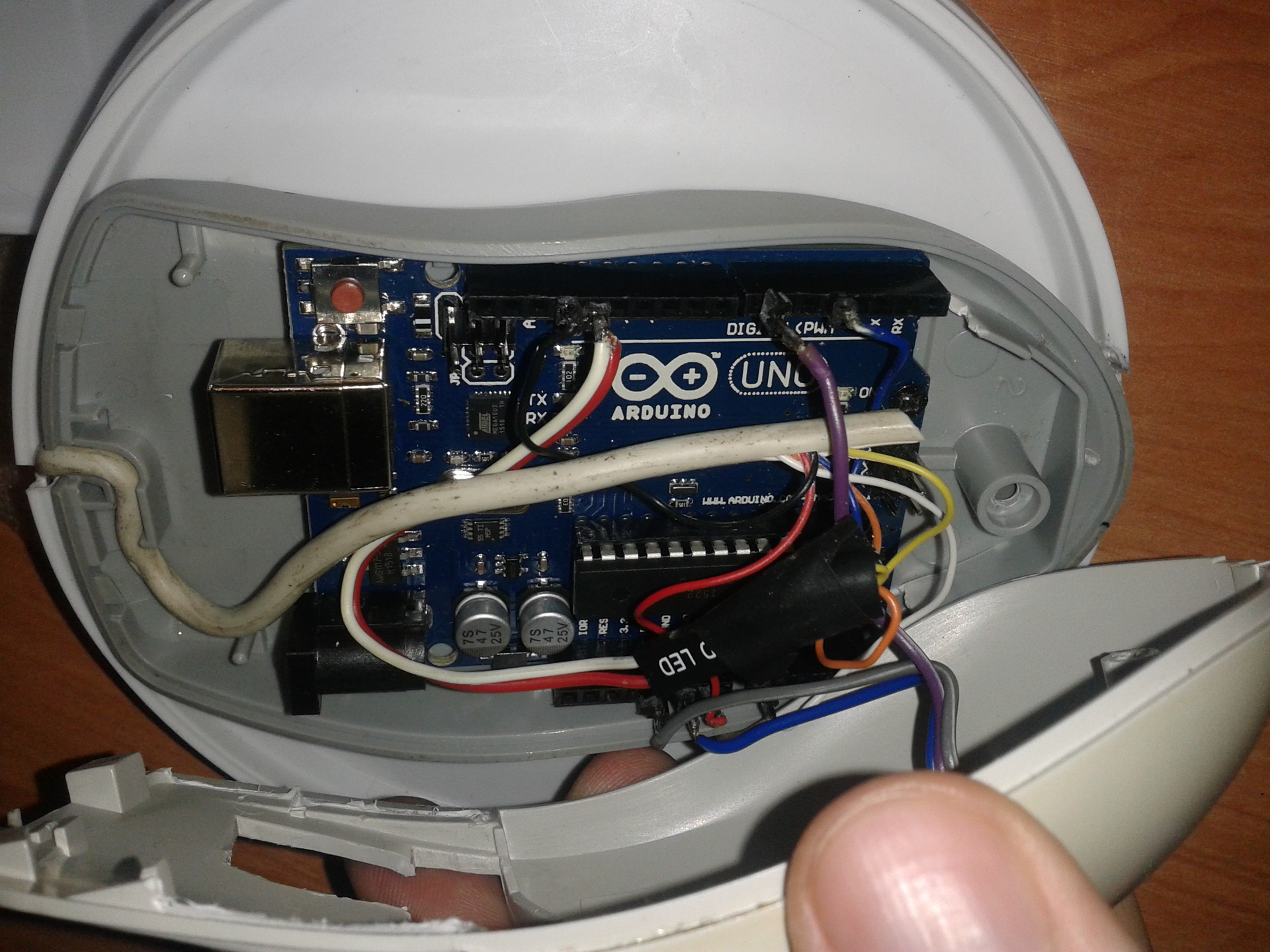
We have decided on the control device, it’s up to the case. Two rather capacious buckets were chosen for the case - from ice cream and cabbage, the microcontroller case ideally fit into the case from the 2003 Genius Easy Mouse Pro PS2 ball mouse.
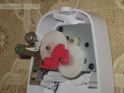
The dosing system will consist of a drive and a regulator. The feed drive is made using an electric motor from an automatic AirWick air freshener. Alternatively, you can use any 3.5 volt motor.
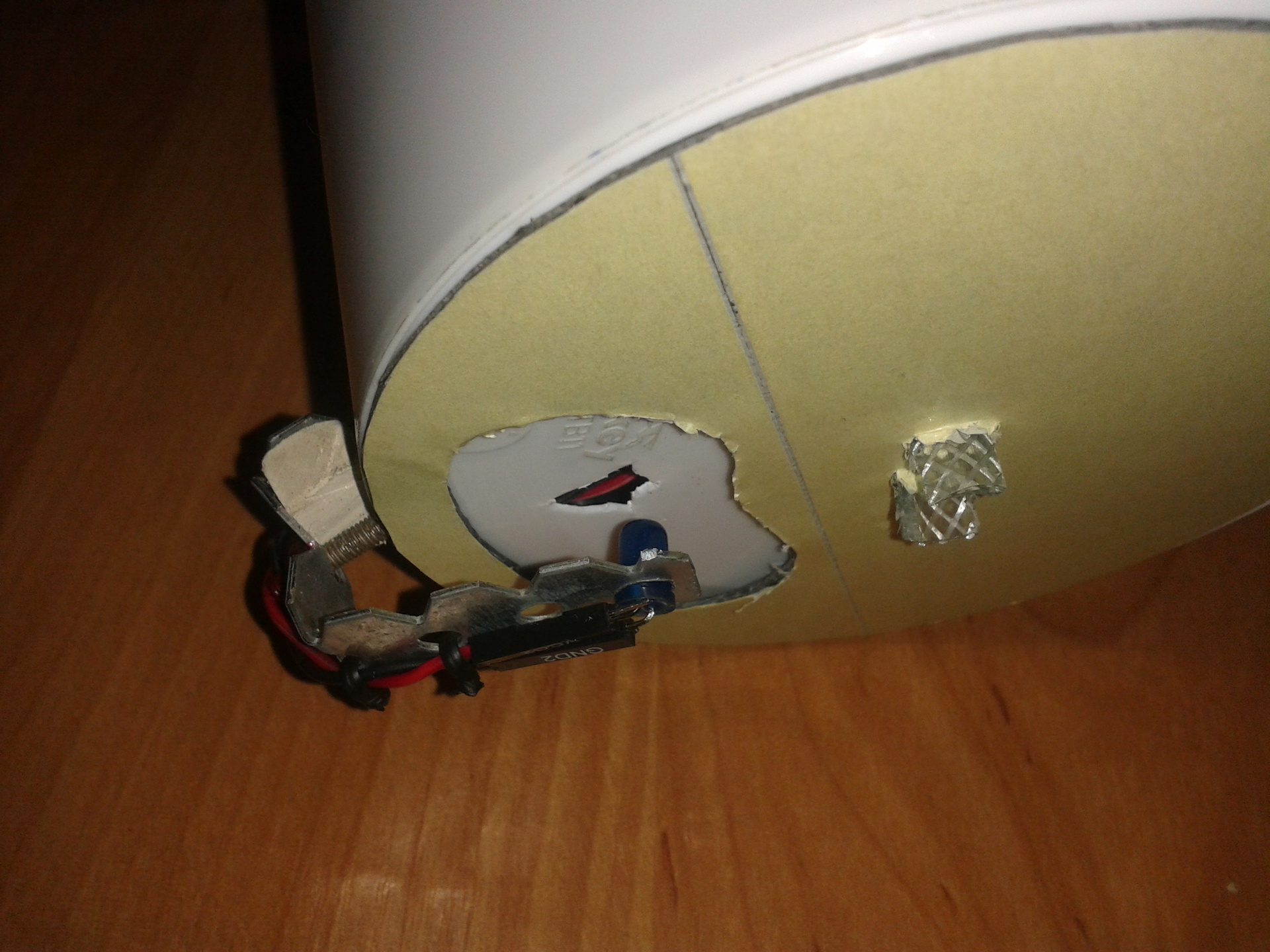
The regulator as a result, it was decided to make a photoconductor and a blue LED, borrowed from a set of a young electrician classmate.
The organization of a kind of “schedule” was decided to be made using a motion sensor, similar to those installed in automatic lighting systems in rooms.
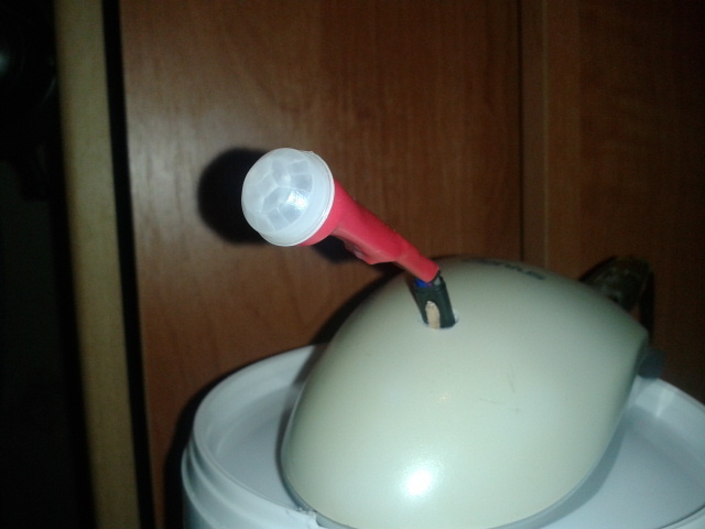
Initially, it was decided to make a delivery schedule with a period of 8 hours, without using any sensors. However, the idea had to be abandoned, due to the unreliability of the system.
Instrument assembly
To begin, we make the necessary holes in the bucket from the cabbage, read the lower part of the body.
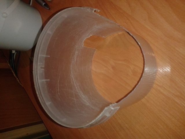
We will need holes for installing the regulator and the feed tank.
At the bottom of the ice cream bucket (upper part) we need a hole for supplying an LED signal to the photoresistor (see above), as well as a larger hole for feeding food. On the side of the bucket we place a hole for attaching the regulator. In the center of the bottom we place the holes for the shaft and its fastening to the circle of the dispenser itself, about the circle will be lower. On the lid on top, we fix the case from the mouse with the microcontroller, simultaneously making holes for the connecting wires.
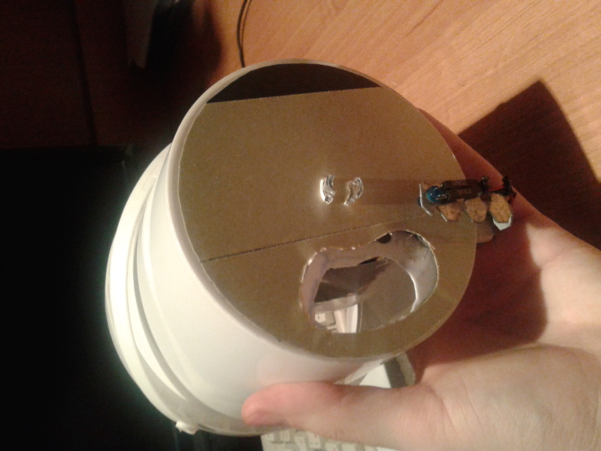
The drive for feeding is made of an electric motor onto the shaft of which is a dispenser. The dispenser, in turn, is made in the form of a plastic circle with a hole cut out. Actually, feed is fed into the tank through the hole by rotating the circle with an electric motor. The electric motor itself with the connected wires is placed at the bottom of the upper part.
Let's move on to the regulator. To do this, you need a U-shaped bracket to mount the photoresistor exactly above the LED. In this case, an aluminum bracket was used for attaching drywall, it was chosen because of its flexibility, as well as convenient holes for attaching the LED itself and the resistor.
Before assembling individual elements, connecting the elements themselves, make sure to connect all wires and smaller elements, the connection diagram:

On the diagram:
PIR is a pyroelectric motion sensor:

M1 is an electric motor, R2 is a 10 kΩ step-down resistor, for which you need to look here , R1 is a 220 Ohm resistor, VD1 is a LED, PR1 is a photoresistor. A1 - Arduino analog input, D7, D4 and D13 - Arduino digital inputs.
After connecting and assembling, we place a protective screen on the periphery, in our case the upper part of the bottle protrudes from soda, so that the feed does not fall on movable parts, it is recommended to use dry food to prevent clogging of the dispenser opening.
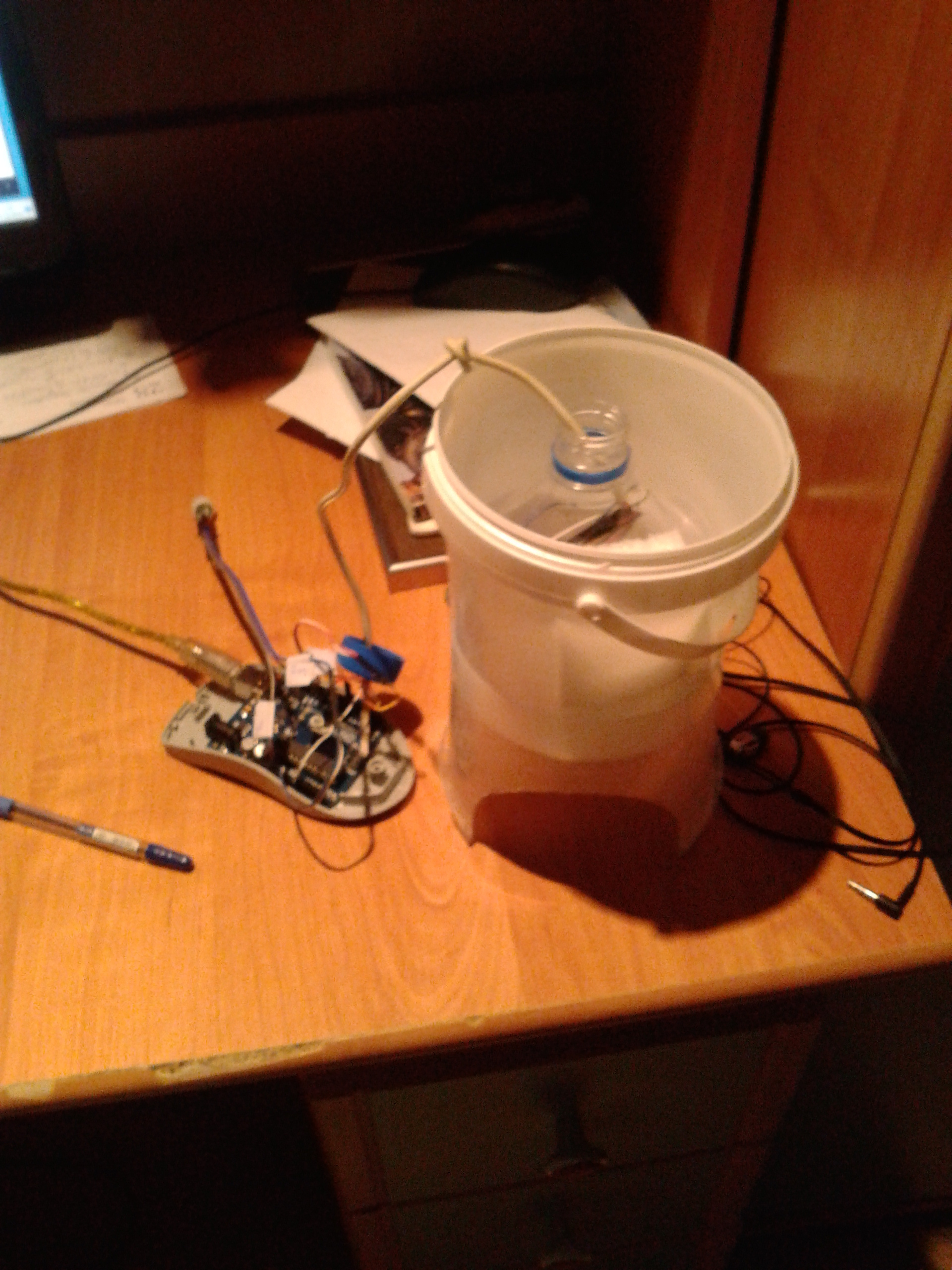
The simplest sketch:
int pirMSPin = 7;
int pirEMPin = 4;
int pirDaPPin = 13;
int portion;
int delayflag;
int sensorValue;
void setup()
{
  pinMode(pirMSPin, INPUT);//motion sensor
  pinMode(pirEMPin, OUTPUT);//electrical motor
  pinMode(pirDaPPin, OUTPUT);//diode and photoresistor
  digitalWrite(pirDaPPin, HIGH);//turn on diode and photoresistor
  Serial.begin(9600);//set baud rate
}
void checkPhoto()
{
   if(sensorValue>600)
    potion++;
}
void turnOffEM()
{
  digitalWrite(pirEMPin, LOW);
}
void makeDelay()
{
  delay(600);
  delayflag=1;
}
void turnOnEM()
{
  digitalWrite(pirEMPin, HIGH);
}
void loop()
{
  portion=0;
  delayflag=0;
  //digitalWrite(pirEMPin, LOW);
  int pirValMS = digitalRead(pirMSPin);
  if (pirValMS == HIGH)
  {
    Serial.println("MOVEMENT");
    do{
      sensorValue = analogRead(A0);
      Serial.println(sensorValue);
      checkPhoto();
      Serial.println(flag);
      if(portion==1){
        turnOnEM();
        if(delayflag==0)
          makeDelay();
      }
      if(portion==2)
      turnOffEM();
    }while(portion<2);
    //delay for a portion extraction, AKA timetable for 3 portions a day
    delay(28800000);
  }
  else
  {
    Serial.println("no movement");
  }
 }
Comments on the sketch, as well as the operation of the device
Having received data on the registered movement, a signal is received to start the dosage process. The dosage process begins by reading the value of the photoresistor, if the signal value of the photoresistor is high enough, this means that the photoresistor registers the signal from the LED and the feed mechanism is in the closed position. Then the electric motor starts and the dosing process begins. The batching process ends when the high signal from the photoresistor is re-registered, which is an indicator of the complete batch cycle. After the portion is dispensed, the system goes into standby mode, the duration of which can be set by reprogramming the microcontroller, for this, the delay line (28800000) is used. The number of dosage cycles (portions) can also be set by changing the variable with the speaking name portion,
Issue price
Given that the Arduino controller was available a priori, of the components in the final version it was necessary to pay only for the sensor, which costs about three conventional units.
Eventually
For two evenings of work, we get an affordable system in which the beloved pet will not remain hungry and the wallet will not be empty.