How to work with Shader Graph in Unity3D
- Tutorial
Shader graphs are a new tool for creating shaders in a unit. It allows you to create shaders for people who do not have the skills to write code. The result of each operation is visible when editing. The ideal tool for beginners and experimenters.
Adding a Shader Graph to a project is done using the Package Manager.
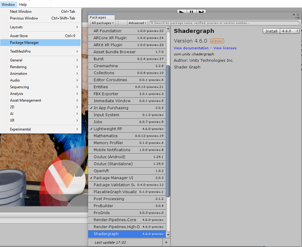
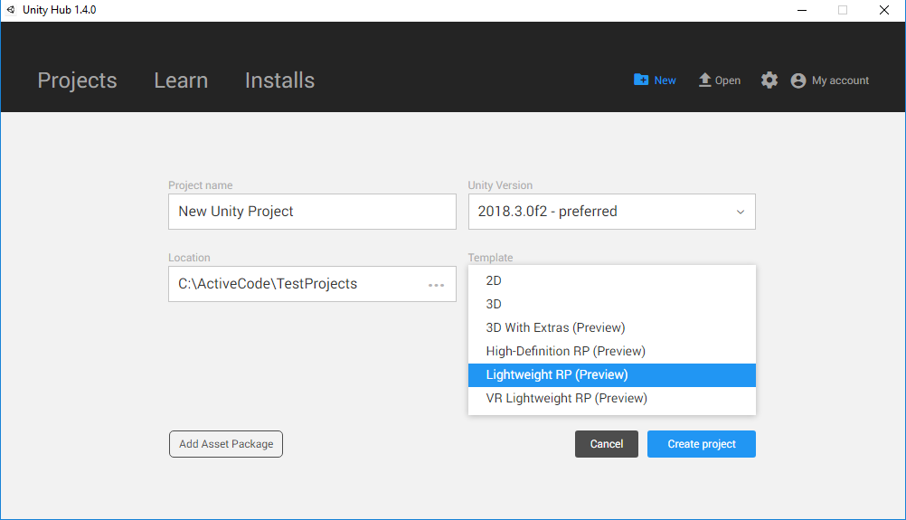
But for today the version is available only for Lightweight Render Pipeline, so for experiments you need to create a project like this:
Simplest shader
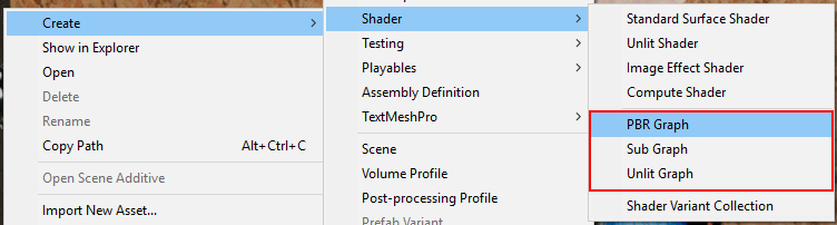
Shader Graph allows you to create two types of shaders Unlit (without lighting) and PBR (photo-realistic render), as well as sub (node for the shader). The latter can be used inside Unlit and PBR shaders.
Unlit does not use the built-in features in the unit for lighting and shading the model, only displays the texture on top of the model and therefore it is much easier to get acquainted with it.
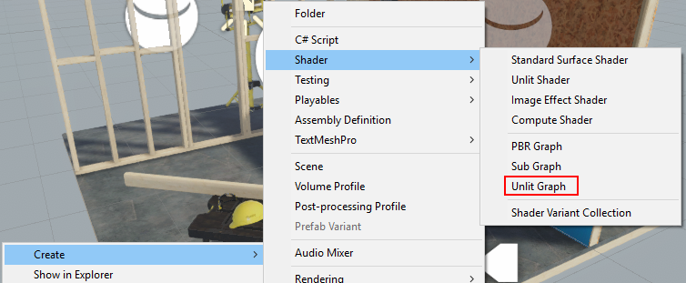
Create material and create Unlit Graph. By dragging, assign a shader to the material.
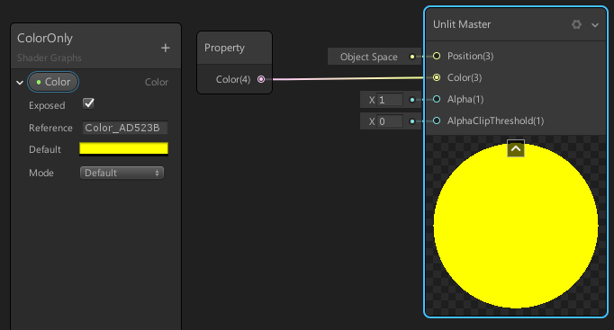
Opening the shader with a double click we will see the master node.
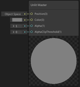
At the output of this shader we can control:
- Position - vertex position
- Color - the color of each pixel of the surface
- Alpha - its transparency
- AlphaClipThreshold - transparency threshold, if we do not use translucency
The vast majority of shaders do not use translucency due to computational complexity and limitations imposed on such shaders. And where you can do without translucency, you have to do without it.
Whether your shader will use translucency or not, you can configure it in the master node:
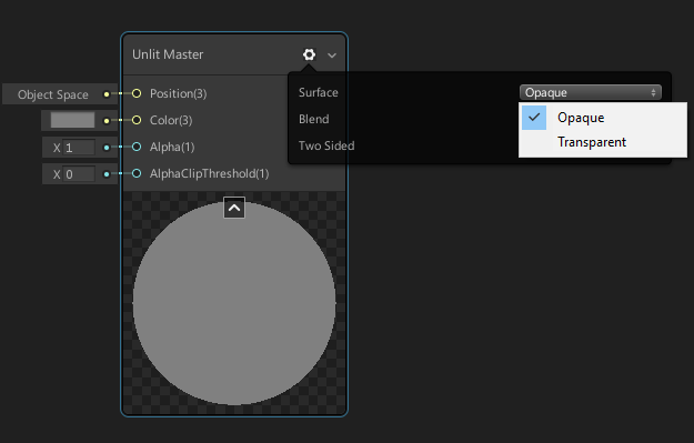
- Opaque - opaque
- Transparent - translucent
To color the model, we can apply a three-dimensional vector or color to the input (color) of the master node, which is essentially the same for the shader, only displayed differently in the graph.
New nodes are created through the context menu
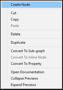
in this case, we can use two Color or Vector4 nodes,

but in order to be able to customize them from the inspector, we need to create a property

and then drag it to the graph with the mouse, thereby creating a node.

- Exposed - allows you to see this property in the inspector when editing material
- Default - sets the default color value
- Mode - allows you to select the brightness range (HDR allows you to go beyond the normal brightness)
In order for the created property to affect the color of the material, its output must be connected to the Color input at the master node.
The same shader, but the code
Shader "Tutorial/Simpliest"// Shader - обязательное начало для любого шейдера, // после этого ключевого слова в// кавычках пишется url-подобное имя шейдера
{
Properties // блок свойств, которые будут отображаться во вкладке // inspector в Unity
{
_Color ("Color", Color) = (0.5,0.6,0.7,1)
//Каждая строка связана с переменной и содержит следующие данные:// _Color - имя переменной, оно должно совпадать по написанию с // одной из переменных внутри CGPROGRAM// "Color" - текст, который будет отображаться в окне // Inspector перед значением переменной// Color - тип данных, от него зависит как будет выглядеть // блок выбора значения в Inspector, бывает// 5 типов данных: // Color - выглядит как выбор цвета, // Vector - как 4 текстовых поля ввода,// Float - поле ввода одного числа с плавающей запятой, // 2D - текстура, // CUBE - выбор кубической текстуры// (0.5,0.6,0.7,1) - значение переменной по умолчанию
}
SubShader // в одном шейдере может быть несколько этих блоков, // но одновременно работать может только один
{
// No culling or depth// Это зарезервированные слова, в этом шейдере они указаны // для упрощения работы GPU, благодаря им потребуется меньше // вычислений для отображения шейдера, а ZTest Always говорит // о том, что этот шейдер будет рисовать объект поверх всех остальных
Cull Off
ZWrite Off
ZTest Always
Pass // этих блоков может быть несколько внутри одного SubShader,// каждый Pass это отдельный проход рендера по объекту с этим // шейдером, результат следующего Pass рисуется поверх предыдущего
{
CGPROGRAM // Зарезервированное слово, оно лишь отмечает начало // кода самого шейдера
#pragma vertex vert_img // использовать для вертексного шейдера // vert_img, которая описана не нами
#pragma fragment frag // для фрагментного шейдера использовать //функцию frag, описанную ниже
#include "UnityCG.cginc"// позволяет нам использовать готовые функции, // написанные командой Unity// в их числе и vert_img, код файла можно найти // в файле:// %UNITY%\Editor\Data\CGIncludes\UnityCG.cginc
fixed4 _Color; // fixed4 - тип переменной, именно этот тип представляет // собой структуру из 4х переменных типа fixed
fixed4 frag(v2f_img i) : COLOR
{
fixed4 col = _Color;
return col;
}
ENDCG // Зарезервированное слово, оно отмечает конец кода самого шейдера
}
}
}
The easiest shader with texture
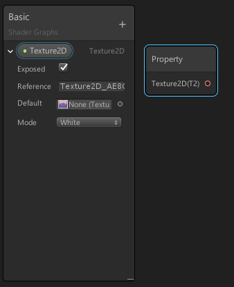
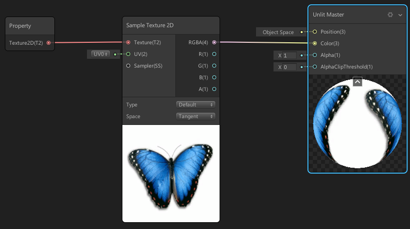
To put our texture on the mesh, we need to create a node that can be configured from the outside by the Shader Graph. To do this, we will create a property
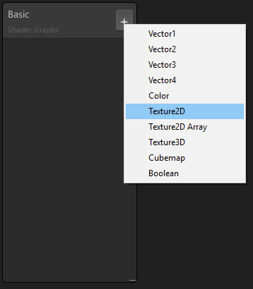
and stretch it out, and a texture node will be created.
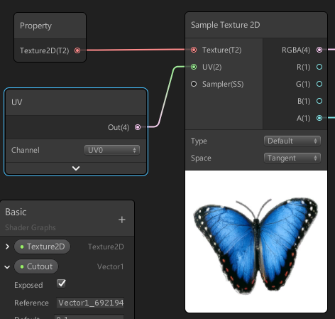
After this, we need to create a texture sampler node, which will be able to receive the texture and uv-coordinate as input, and give the pixel color as output.
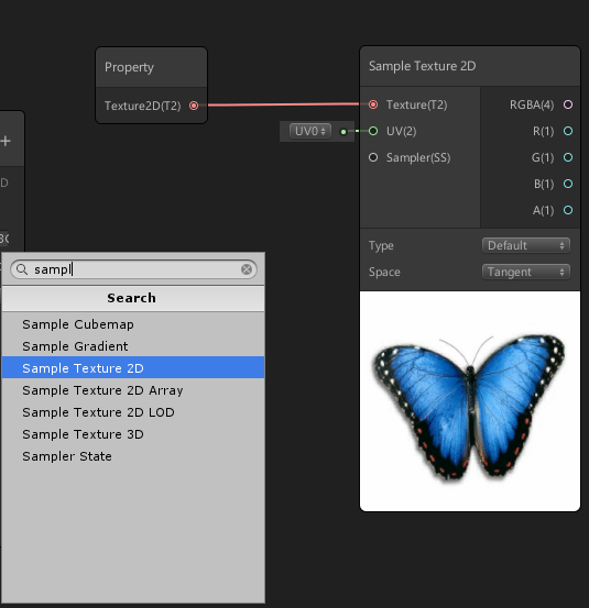
The sampler output is connected to the master color node's input.
Simplest shader with texture code
Shader "Tutorial/Texture"
{
	Properties
	{
		_MainTex("Texture", 2D) = "white" {}
		// В предыдущей части в качестве свойства был цвет, // а теперь текстура, в Inspector будет предложено// выбрать одну. Здесь "white" это значение по умолчанию,// означает, что будет создана текстура белого цвета.
	}
	SubShader
	{
		Cull Off
		ZWrite Off
		ZTest Always
		Pass
		{
			CGPROGRAM
			#pragma vertex vert_img
			#pragma fragment frag
			#include "UnityCG.cginc"
			sampler2D _MainTex;
			// sampler2D - это тип переменной который надо ставить когда// мы хотим работать с текстурой, заметьте, что имя переменной// _MainTex совпадает с именем свойства в блоке Properties,// это обязательно для корректной работы.fixed4 frag(v2f_img i) : COLOR
			{
				// Следующая строка позволяет нам получить цвет пикселя в точке// с которой мы работаем в этой итерации, если помните, то ранее // было сказано, что фрагментный шейдер работает с каждым видимым // пикселем объекта. // tex2D - это готовая функция для получения значения цвета,// первый параметр (_MainTex) это из какой текстуры мы хотим// получить цвет, а второй (i.uv) это UV координаты в которых // мы хотим узнать цвет.
				fixed4 col = tex2D(_MainTex, i.uv);
				return col;
			}
			ENDCG
		}
	}
}
Negative texture
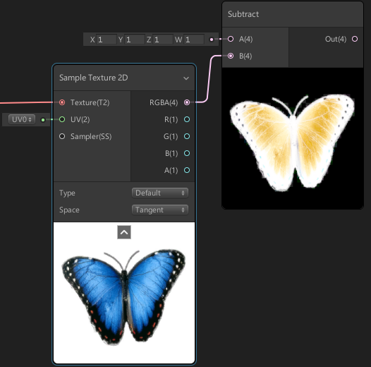
Before displaying the texture on the screen, we can change it by applying mathematical operations. For example, create a negative by simple subtraction.
Add a substract subtract that will be reduced (1; 1; 1; 1), and the texture subtracted by the output.
Negative texture code
Shader "Tutorial/Texture"
{
	Properties
	{
		_MainTex("Texture", 2D) = "white" {}
	}
	SubShader
	{
		Cull Off
		ZWrite Off
		ZTest Always
		Pass
		{
			CGPROGRAM
			#pragma vertex vert_img
			#pragma fragment frag
			#include "UnityCG.cginc"
			sampler2D _MainTex;
			fixed4 frag(v2f_img i) : COLOR
			{
				fixed4 col = tex2D(_MainTex, i.uv);
				col = 1 - col;
				// Инверсия цвета, цвет в шейдере представлен 4-мя компонентами// RedGreenBlueAlpha - КрасныйЗелёныйСинийНепрозрачность,// причём значение каждого компонента в диапазоне от 0 до 1return col;
			}
			ENDCG
		}
	}
}
Mixing two textures
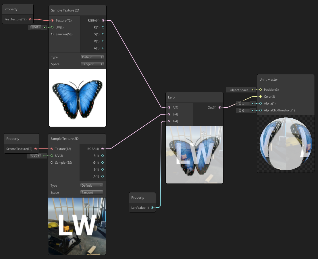
In order to mix two textures, we need three properties, two of which will be textures, and the third number, which will indicate to what extent they should be mixed.
And the blending operation itself will produce a Lerp node.
Mixing two textures by code
Shader "Tutorial/NoiseOverlay"
{
Properties
{
_MainTex("Main Texture", 2D) = "white" {}
_NoiseTex("Noise Texture", 2D) = "white" {}
_LerpValue("Lerp Value", Range(0, 1)) = 0.5
}
SubShader
{
Cull Off
ZWrite Off
ZTest Always
Pass
{
CGPROGRAM
#pragma vertex vert_img
#pragma fragment frag
#include "UnityCG.cginc"
sampler2D _MainTex;
sampler2D _NoiseTex;
float _LerpValue;
fixed4 frag(v2f_img i) : COLOR
{
half4 base = tex2D(_MainTex, i.uv);
half4 overlay = tex2D(_NoiseTex, i.uv);
return lerp(base, overlay , _LerpValue);
}
ENDCG
}
}
}
Cutout mask
To make a part of the model completely transparent, you need to input the Alpha channel value to the master node input, create a slider property and apply it to the AlphaClipThreshold input. The
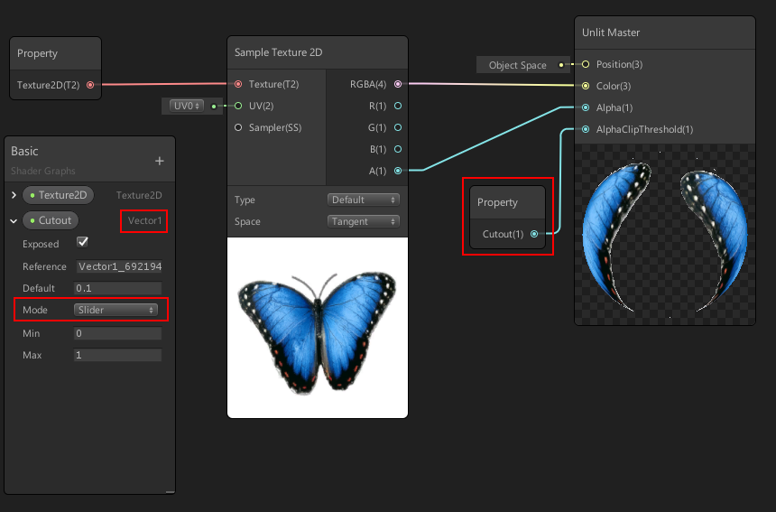
slider is needed to fix a bug in the Graph shader that does not allow cutout, and besides, it will allow changing the value from material settings.
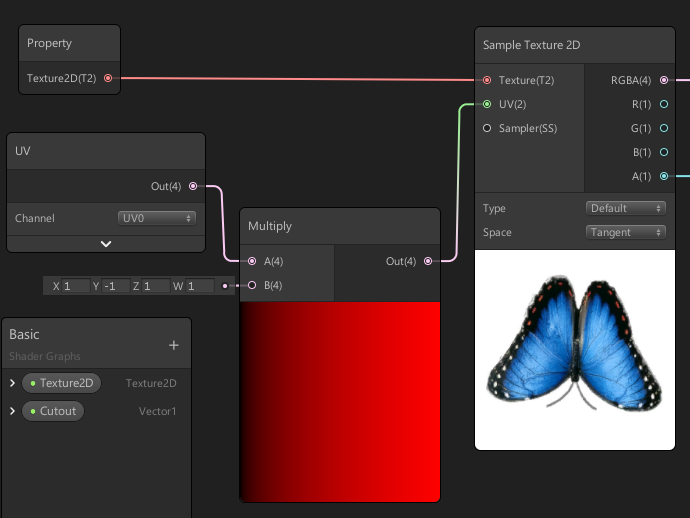
UV inversion
To work with UV, you need to create a node for UV and connect it to the texture sampler.
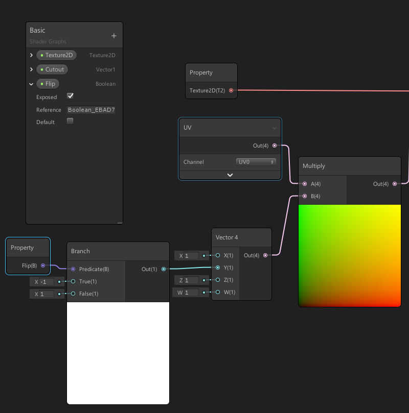
Here you can also select the UV channel, some models of these channels may have several, in case of multi-layered textures. With this step, we didn’t change anything, but to invert UV, we need to create a node that inverts UV values, we can use the usual multiplication by -1 Y coordinates.
Texture mapping can be customized from the material; gets a boolean value on input, and one of two values on output, in our case 1 or -1
Impressions
Creating a shader with Shader Graph greatly simplifies the task, if only because you can observe the change in the result after each step of the computation. The principle of creation through the editor node allows you to create something new even to those who do not understand anything in shaders. The tool is still raw, but already very useful. Since you can experiment in the editor, and then reproduce the code, the names of the functions in most cases coincide with the name of the nodes, so the Shader Graph can be useful to programmers.
PS I thank Darkirius for the help in the preparation of the
PPS article . You can also get acquainted with the lessons on writing shaders in the unit at the link Hit-book