Learn OpenGL. Lesson 4.10 - Instancing
- Transfer
- Tutorial

Instancing
Imagine that you conceived a scene containing a huge number of object models, and these models mainly contain the same vertex data, only the transformation matrices applied to them differ. For example, a scene with a grass field, where each blade of grass is represented by a small model composed literally of a pair of triangles. Of course, to achieve the desired effect, you will have to render this model not once, but a thousand, ten thousand times per frame. Since each leaf contains literally a pair of triangles, its rendering will be almost instant. But here thousands of repeated calls to render functions together will hit performance very noticeably.
Content
Part 1. Getting Started
Part 2. Basic lighting
Part 3. Download 3D models
Part 4. Advanced OpenGL Features
Part 5. Advanced Lighting
Part 6. PBR
- Opengl
- Window creation
- Hello window
- Hello triangle
- Shaders
- Textures
- Transformations
- Coordinate systems
- Camera
Part 2. Basic lighting
Part 3. Download 3D models
Part 4. Advanced OpenGL Features
- Depth test
- Stencil test
- Color mixing
- Clipping faces
- Frame buffer
- Cubic cards
- Advanced data handling
- Advanced GLSL
- Geometric shader
- Instancing
- Smoothing
Part 5. Advanced Lighting
- Advanced lighting. Blinn-Fong model.
- Gamma correction
- Shadow cards
- Omnidirectional shadow maps
- Normal mapping
- Parallax mapping
- HDR
- Bloom
- Deferred rendering
- SSAO
Part 6. PBR
If we really planned to output a lot of objects in the scene in the described way, then in the code it would look something like this:
for (unsigned int ix = 0; ix < model_count; ++ix)
{
     // привязка VAO, текстур, установка юниформов, проч...
    DoSomePreparations();
    glDrawArrays(GL_TRIANGLES, 0, vertex_count);
}
When rendering multiple instances of the same model, we will quickly reach the bottleneck in terms of performance - it will be many calls to the primitive rendering functions. Compared to the time it takes to render directly, passing data to the GPU saying that you want to render something using functions like glDrawArrays or glDrawElemenetstakes a very tangible time. This time is spent on the preparation required by OpenGL before the direct output of vertex data: transferring data to the GPU about the current data reading buffer, location and format of the vertex attribute data, etc., etc. And all this exchange is carried out on a relatively slow bus connecting the CPU and GPU. There is a paradoxical situation: the rendering of vertex data is lightning fast, but the transfer of commands for rendering is rather slow.
It would be great to be able to send the necessary data to the video card once, and then just ask OpenGL to render many objects using this data with just one call. Welcome to the world of instancing !
Instancing is a technology that allows you to display many objects using a single call to the draw function, which saves us from unnecessary CPU -> GPU exchange during rendering. All you need to do to start using instancing: change glDrawArrays and glDrawElemenets to glDrawArraysInstanced and glDrawElementsInstancedrespectively. Versions that support instancing accept one additional parameter, in addition to functions that are already familiar from regular versions. This parameter is the number of instances, i.e. the number of instances of the model to render. Thus, we feed the GPU once all the data necessary for rendering, and then tell it how to render the desired number of object instances in just one call to a special function. And the video card will draw all the many objects without constantly accessing the CPU.
Such an opportunity in itself is not very useful: having displayed thousands of objects in the same way, in the same position, we will still end up with an image of a single object - all copies will be superimposed on each other. To solve this problem in vertex shaders, the available GLSL built-in variablegl_InstanceID .
When using functions that support instancing for rendering, the value of this variable will increase by one for each displayed instance, starting from zero. Thus, rendering the 43rd instance of the object, in the vertex shader we get gl_InstanceID equal to 42. Having a unique index corresponding to the instance, we could, for example, use it to select from a large array of position vectors in order to render each instance in a specific place in the scene .
To get a better feel for the essence of instantiation, let's try to figure out a simple example that renders a hundred quads (rectangles) in the normalized device coordinates (NDC) with a single draw call. The offset is determined using a selection from the uniform, which is an array containing one hundred offset vectors. The result is a nice grid of rectangles filling the entire window area:
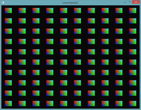
Each quad is made up of two triangles, which gives us six vertices. Each vertex contains a two-component position vector in NDC and a color vector. The vertex data from the example is presented below - the size of the triangles is selected small enough to correctly fill the screen in large quantities:
 float quadVertices[] = {
    // координаты  // цвета
    -0.05f,  0.05f,  1.0f, 0.0f, 0.0f,
     0.05f, -0.05f,  0.0f, 1.0f, 0.0f,
    -0.05f, -0.05f,  0.0f, 0.0f, 1.0f,
    -0.05f,  0.05f,  1.0f, 0.0f, 0.0f,
     0.05f, -0.05f,  0.0f, 1.0f, 0.0f,
     0.05f,  0.05f,  0.0f, 1.0f, 1.0f
};
The color of the quad is determined by the fragment shader, which simply redirects the interpolated color of the vertex obtained from the vertex shader directly to the output variable:
#version 330 core
out vec4 FragColor;
in vec3 fColor;
void main()
{
    FragColor = vec4(fColor, 1.0);
}
Nothing new for us. But in the vertex shader, things are different:
#version 330 core
layout (location = 0) in vec2 aPos;
layout (location = 1) in vec3 aColor;
out vec3 fColor;
uniform vec2 offsets[100];
void main()
{
    vec2 offset = offsets[gl_InstanceID];
    gl_Position = vec4(aPos + offset, 0.0, 1.0);
    fColor = aColor;
}
Here we announced Uniform array offsets , containing one hundred and displacement vectors. In the shader code, we get the offset value by fetching from the array by the value of the gl_InstanceID variable . As a result, using this shader, we can render hundreds of quads located in different positions on the screen.
However, additional work is required - the displacement array itself will not fill up. Fill it in our application, before entering the main rendering cycle:
glm::vec2 translations[100];
int index = 0;
float offset = 0.1f;
for(int y = -10; y < 10; y += 2)
{
    for(int x = -10; x < 10; x += 2)
    {
        glm::vec2 translation;
        translation.x = (float)x / 10.0f + offset;
        translation.y = (float)y / 10.0f + offset;
        translations[index++] = translation;
    }
}
Here, hundreds of transfer vectors are created that define a uniform 10x10 grid.
Do not forget to transfer the generated data to the uniform array of the shader:
shader.use();
for(unsigned int i = 0; i < 100; i++)
{
    stringstream ss;
    string index;
    ss << i;
    index = ss.str();
    shader.setVec2(("offsets[" + index + "]").c_str(), translations[i]);
}
In this piece of code, we convert the loop variable i to a variable of type string to be able to dynamically set the string of the name of the uniform and get the location of the uniform by that name. For each element from the offsets uniform array, we pass the corresponding generated offset vector.
If C ++ 11 and newer is available, it is better to use std :: to_string (). Note.per.Now that the preparatory work is completed, you can finally proceed to render. Let me remind you that you must use glDrawArraysInstanced or glDrawElementsInstanced to invoke the instant renderer. Since we do not use the index buffer in the example, the following code is used:
glBindVertexArray(quadVAO);
glDrawArraysInstanced(GL_TRIANGLES, 0, 6, 100);
The parameters passed to the render function are identical to those passed to glDrawArrays , with the exception of the last parameter, which sets the desired number of instances to render. Since we want to display 100 quads in a 10x10 grid, we pass the number 100. Executing the code should lead to the output of an already familiar picture with hundreds of colorful rectangles.
Installed Arrays
The previous example is quite working and copes with its task. But there is a problem: if our appetites grow, and we want to bring out much more than 100 copies, then very soon we will hit the ceiling of the allowed volume of uniform data sent to the shader. An alternative data transmission via Uniform are instansirovannye arrays ( instanced arrays ), which are defined as the vertex attributes, the sample of which occurs only when changing the current index pre-rendered object instance. As a result, this allows you to transfer much larger amounts of data in a more convenient way.
For ordinary vertex attributes, GLSL fetches new vertex data values with each subsequent execution of the vertex shader code. However, setting the vertex attribute as an instantiated array, we force GLSL to select a new attribute value for each successive instance of the object, rather than the next vertex of the object. As a result, you can use the usual vertex attributes for the data presented vertically, and instantiated arrays for the data unique to the object instance.
To better understand how this works, we modify the example code to use an instantiated array instead of a uniform array. You will have to update the shader code by setting a new vertex attribute:
#version 330 core
layout (location = 0) in vec2 aPos;
layout (location = 1) in vec3 aColor;
layout (location = 2) in vec2 aOffset;
out vec3 fColor;
void main()
{
    gl_Position = vec4(aPos + aOffset, 0.0, 1.0);
    fColor = aColor;
}
Here we no longer use the gl_InstanceID variable and can directly access the offset attribute , without the need to select from an array.
Since the implementation of the instantiated array is essentially based on vertex attributes, such as position or color , it is necessary to save the data in the vertex buffer object and configure the pointer of the vertex attribute. First, save the translations array data in a new buffer object:
unsigned int instanceVBO;
glGenBuffers(1, &instanceVBO);
glBindBuffer(GL_ARRAY_BUFFER, instanceVBO);
glBufferData(GL_ARRAY_BUFFER, sizeof(glm::vec2) * 100, &translations[0], GL_STATIC_DRAW);
glBindBuffer(GL_ARRAY_BUFFER, 0);
Also, configure the pointer of the vertex attribute and activate the attribute:
glEnableVertexAttribArray(2);
glBindBuffer(GL_ARRAY_BUFFER, instanceVBO);
glVertexAttribPointer(2, 2, GL_FLOAT, GL_FALSE, 2 * sizeof(float), (void*)0);
glBindBuffer(GL_ARRAY_BUFFER, 0);
glVertexAttribDivisor(2, 1);
The code is familiar, except for the last line with a call to glVertexAttribDivisor . This function tells OpenGL when to select a new element from the vertex attribute. The first parameter - the index of the attribute of interest, and the second - an attribute delimiter ( the attribute divisor ). By default, it is set to 0, which corresponds to updating the attribute for each new vertex processed by the vertex shader. By setting this parameter to 1, we inform OpenGL that we should update the attribute when rendering each subsequent instance. By setting the delimiter to 2, we will provide updates every two instances, and so on. In fact, setting the separator to 1, we indicate that the attribute with this separator is represented by an instantiated array.
If we now draw a scene using glDrawArraysInstanced , we get the following picture:
Exactly the same as last time, but implemented using an instantiated array, which allows you to transfer much more data to the vertex shader to ensure an instantiated rendering.
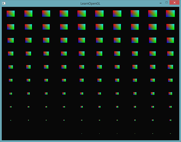
Purely from pranks, we will try to gradually reduce each quad, starting from the upper right corner in the direction of the lower left corner. We use the gl_InstanceID variable again , because why not?
void main()
{
    vec2 pos = aPos * (gl_InstanceID / 100.0);
    gl_Position = vec4(pos + aOffset, 0.0, 1.0);
    fColor = aColor;
}
As a result, we get a picture where the first copies are rendered tiny, but with the instance number approaching 100, the size of each rectangle tends to the original one. This sharing of instantiated arrays and gl_InstanceID is fully acceptable.
If you doubt that you have properly mastered the principle of the work of the rendered render or just want to study the device of the entire sample code, then the source code is available here .
All this, of course, is good, but these examples give a poor idea of the real benefits of instancing. Of course, the technical details are shown here, but the essence of the instances is revealed only when rendering a crazy amount of similar objects - something that we have not yet reached. That is why in the next section we will have to go into outer space in order to personally see the true power of instancing.
Asteroid field
Imagine a scene where a huge planet is surrounded by a massive belt of asteroids. Such a belt may well contain thousands or even tens of thousands of rock formations. The conclusion of such a scene will very quickly become almost impossible on any good video card. But it is in this scenario that the use of instantiation suggests itself, since all the asteroids of the belt can be represented as a single model. Each asteroid will be slightly different from its neighbors due to its unique transformation matrix.
To show the positive effect of instancing, we first try to bring this scene out without using it. The scene will contain a large planet, a model of which can be downloaded here, as well as a large set of asteroids, specially located around the planet. Asteroid model can be downloaded here .
In the application code, we load model data using the bootloader, which was covered in modeling lessons .
To achieve the necessary configuration of the scene, we will create a transformation matrix unique to each asteroid, which will be used as a model matrix when rendering each of them. The matrix is formed in several stages. First, the transfer transformation is applied to place the asteroid somewhere within the ring. We also apply a small random bias to add realism to the distribution of asteroids. Then random scaling and rotation around the rotation vector are added. As a result, we get a transformation matrix that places each asteroid somewhere in the vicinity of the planet, at the same time providing its unique look. And the asteroid belt is filled with a bunch of blocks of stone unlike each other.
unsigned int amount = 1000;
glm::mat4 *modelMatrices;
modelMatrices = new glm::mat4[amount];
srand(glfwGetTime()); // задаем seed для генератора случ. чисел
float radius = 50.0;
float offset = 2.5f;
for(unsigned int i = 0; i < amount; i++)
{
    glm::mat4 model(1.0f);
    // 1. перенос: расположить вдоль окружности радиусом 'radius'
    // и добавить смещение в пределах [-offset, offset]
    float angle = (float)i / (float)amount * 360.0f;
    float displacement = (rand() % (int)(2 * offset * 100)) / 100.0f - offset;
    float x = sin(angle) * radius + displacement;
    displacement = (rand() % (int)(2 * offset * 100)) / 100.0f - offset;
    // высоту поля держим заметно меньшей, чем размеры в плоскости XZ
    float y = displacement * 0.4f;
    displacement = (rand() % (int)(2 * offset * 100)) / 100.0f - offset;
    float z = cos(angle) * radius + displacement;
    model = glm::translate(model, glm::vec3(x, y, z));
    // 2. масштабирование: случайное масштабирование в пределах (0.05, 0.25f)
    float scale = (rand() % 20) / 100.0f + 0.05;
    model = glm::scale(model, glm::vec3(scale));
    // 3. поворот: поворот на случайный угол вдоль
    float rotAngle = (rand() % 360);
    model = glm::rotate(model, rotAngle, glm::vec3(0.4f, 0.6f, 0.8f));
    // 4. добавляем в массив матриц
    modelMatrices[i] = model;
}
This code fragment may seem intimidating, but here we just place each asteroid in the XZ plane along a circle defined by radius radius , and also add a small random offset within (- offset , offset ) relative to this circle. We change the Y coordinate to a lesser extent in order to give the asterodian ring the shape of the ring itself. In addition, scaling and rotation are applied, and the result is stored in an array of modelMatrices matrices with the amount amount. In this example, 1000 model matrices are created, one per asteroid.
After loading the planet and asteroid models, as well as compiling the shaders, you can proceed to the rendering code:
// рендер планеты
shader.use();
glm::mat4 model(1.0f);
model = glm::translate(model, glm::vec3(0.0f, -3.0f, 0.0f));
model = glm::scale(model, glm::vec3(4.0f, 4.0f, 4.0f));
shader.setMat4("model", model);
planet.Draw(shader);
// рендер метеоритов
for(unsigned int i = 0; i < amount; i++)
{
    shader.setMat4("model", modelMatrices[i]);
    rock.Draw(shader);
}
First, we draw a model of the planet, which has to be slightly shifted and scaled so that it fits into the scene. Then render the asteroids in an amount equal to the amount of the prepared array of transformations. Before the output of each asteroid, we have to transfer the corresponding data to a uniform containing a model matrix.
It turns out a picture resembling a photograph from space, with a fairly plausibly looking planet surrounded by an asteroid belt:
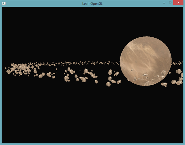
This scene performs 1001 calls to the rendering functions per frame, 1000 of which fall on the asteroid model. Sources are here .
If we begin to increase the number of displayed asteroids, we quickly notice that the scene ceases to be redrawn smoothly, and the number of frames per second drops sharply. As soon as we get to trying to bring out 2000 asteroids, the render becomes so unresponsive that simply moving around the scene is almost impossible.
Now, let's try to do the same, but using instancing. First, tweak the vertex shader a bit:
#version 330 core
layout (location = 0) in vec3 aPos;
layout (location = 2) in vec2 aTexCoords;
layout (location = 3) in mat4 instanceMatrix;
out vec2 TexCoords;
uniform mat4 projection;
uniform mat4 view;
void main()
{
    gl_Position = projection * view * instanceMatrix * vec4(aPos, 1.0);
    TexCoords = aTexCoords;
}
We no longer use uniforms containing a model matrix. Instead, we declare a new vertex attribute that stores the matrices, in which we will place the instantiated array of transformation matrices. It is worth noting that when specifying the vertex attribute with the type size exceeding the vec4 size , one peculiarity must be taken into account. Since mat4 in fact it is four connected vec4 , then this attribute will be set aside as much as four index location ( location The ) vertex attribute. Here we assigned the attribute a placement index of 3, which means the columns of the matrix receive placement indices of 3, 4, 5, and 6.
In the client code, we will have to set pointers to vertex attributes for each of these implicitly specified location indices. And do not forget to initialize each of them as an instantiated array:
// создаем VBO
unsigned int buffer;
glGenBuffers(1, &buffer);
glBindBuffer(GL_ARRAY_BUFFER, buffer);
glBufferData(GL_ARRAY_BUFFER, amount * sizeof(glm::mat4), &modelMatrices[0], GL_STATIC_DRAW);
for(unsigned int i = 0; i < rock.meshes.size(); i++)
{
    unsigned int VAO = rock.meshes[i].VAO;
    glBindVertexArray(VAO);
    // настройка атрибутов
    GLsizei vec4Size = sizeof(glm::vec4);
    glEnableVertexAttribArray(3);
    glVertexAttribPointer(3, 4, GL_FLOAT, GL_FALSE, 4 * vec4Size, (void*)0);
    glEnableVertexAttribArray(4);
    glVertexAttribPointer(4, 4, GL_FLOAT, GL_FALSE, 4 * vec4Size, (void*)(vec4Size));
    glEnableVertexAttribArray(5);
    glVertexAttribPointer(5, 4, GL_FLOAT, GL_FALSE, 4 * vec4Size, (void*)(2 * vec4Size));
    glEnableVertexAttribArray(6);
    glVertexAttribPointer(6, 4, GL_FLOAT, GL_FALSE, 4 * vec4Size, (void*)(3 * vec4Size));
    glVertexAttribDivisor(3, 1);
    glVertexAttribDivisor(4, 1);
    glVertexAttribDivisor(5, 1);
    glVertexAttribDivisor(6, 1);
    glBindVertexArray(0);
}
I note that here we cheated a little, declaring VAO as a public, and not a private variable of the Mesh class - this allowed us to simplify access to the vertex array object. It may not be the most elegant and clean solution, but for the needs of a simple example it will do. Besides this small hack, the rest of the code should be clear. Here we simply indicate how OpenGL should interpret the contents of the buffer for each element of the vertex attribute represented by the matrix. We also indicate that each of these attributes is an instantiated array.
Next, we again turn to the VAO prepared models and call the render:
// draw meteorites
instanceShader.use();
for(unsigned int i = 0; i < rock.meshes.size(); i++)
{
    glBindVertexArray(rock.meshes[i].VAO);
    glDrawElementsInstanced(
        GL_TRIANGLES, rock.meshes[i].indices.size(), GL_UNSIGNED_INT, 0, amount
    );
}
Here, rendering is carried out with the same number of asteroids as in the previous example, but now it uses instancing. Visually, the result will be similar. The main difference will manifest itself with an increase in the number of asteroids. Without instancing, we could squeeze a smooth render from the video card in the range from 1000 to 1500 asteroids. With instances, we can calmly raise the bar to an incredible 100,000 asteroids. Given that each of them contains 576 vertices, we get approximately 57 million processed vertices without any drop in performance!

This image was obtained with the output of 100,000 asteroids with variables radius = 150.0f and offset = 25.0f . The source code is here .
Everyone has different configurations of working machines, so the limit of 100,000 may be somewhat optimistic. Try adjusting the specific number in your case so that the frame rate remains acceptable.As you can see, in certain tasks, instancing can give a significant gain in performance. That is why this technique is used to render grass, plants, particle systems, and other scenes similar to those shown in the lesson - essentially any such where one object is displayed multiple times.
PS : We have a telegram conf for coordination of transfers. If you have a serious desire to help with the translation, then you are welcome!