Arduin and LED, or how to pump the children's designer

My son is firmly hooked on the Magformers magnetic designer . Once, looking through a series of Fixics where the same designer appeared, the child asked: “Dad, why do parts of shine fixes glow, but don't we?”.
It turned out that there really is a “Magformers Neon LED Set”, where besides the usual building blocks there is also an element with an LED. Since by this time we already had a whole box of magnets of all possible shapes and sizes (as for me, the Chinese magformers are not inferior to the original), I didn’t want to buy another set just for the sake of a light bulb. Moreover, this set cost significantly more expensive than the same without lighting.
Having estimated that there were only a couple of components in there, most of which I already had, I decided to assemble my own hulk. Yes, and with effects that were not in the original.
Under the cat you will find the option of the twinkler on the ATTiny85 and the LED panel on the WS8212 LEDs. I'll tell you about the circuitry, how I fed this whole thing from the battery, as well as the unobvious problems that I raked along the way. I will also talk in detail about the program component of the project.
The first steps
It seemed to me that the light on a regular LED (even if it is RGB) is boring and trite. But to feel something like WS8212 seemed interesting. On ebee, both individual LEDs and matrixes up to 16x16 in size were offered. Having bought several different modules, I stopped at the 4x4 matrix. There are a lot of LEDs in it to indulge in various visual effects, while the module is comparable in size with the window of a square block designer.
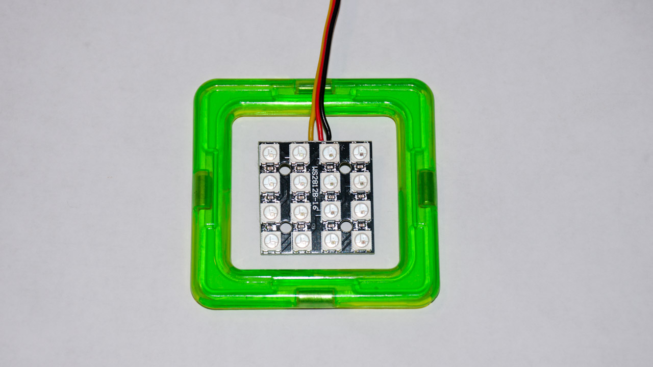
To control the LED matrix, just one pin of the microcontroller is enough, so that even the arduin nano looks like a brute force (besides, it will not fit into the case). But the digispark clone on the ATTiny85 controller turned out to be just right - there is not a lot of memory and pins in it, but more than enough for an LED blinker. The module integrates perfectly with the Arduino IDE and has a USB downloader on board, so programming this module is very simple and comfortable. I have long wanted to try it.
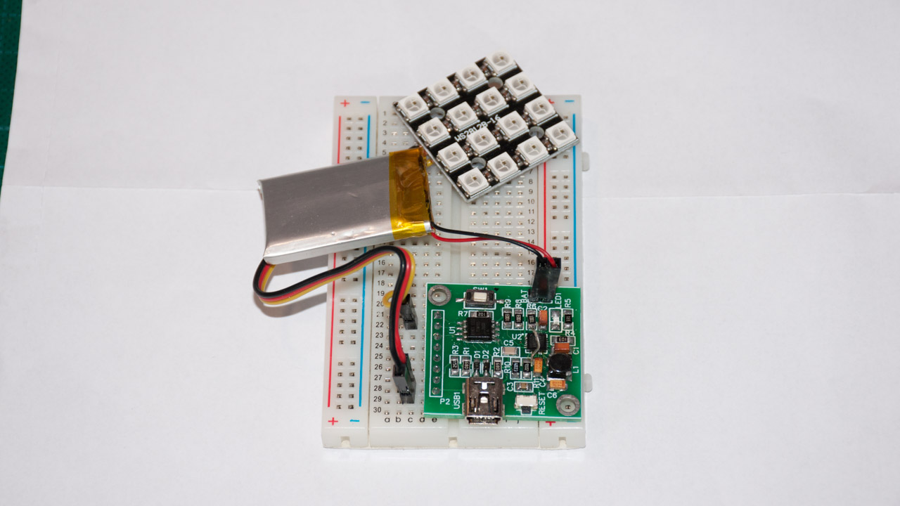
Started with the simplest scheme.

In this form, it was possible to quickly debug all the glow / blink algorithms (see below). But here a toy with wire power is not the case - you need to think about battery power. And in order not to go broke on the finger batteries (which, moreover, do not fit into the envelope), it was decided to use lithium batteries. And since there is a lithium battery, then you need to think about how to charge it. In the bins, I just found a “popular” charge controller on the TP4056 microcircuit bought on the occasion .
Only now connect it immediately failed. The circuit of the Digispark ATTiny85 module is not very much designed for this - either there is USB power, but then the power is supplied directly to the microcontroller (via the +5 bus) or from the VIN input, but then the power goes through the 7805 linear stabilizer. inserted into the gap between the USB connector and the microcontroller is not provided. I had to modify a bit of the scheme and remove the extra details.
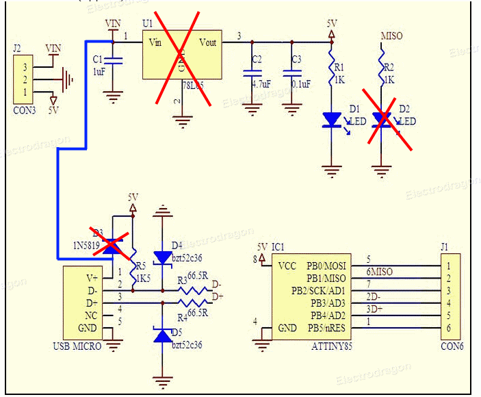
So, now the power from the USB goes to the VIN leg and goes on to the input of the charger. The output of the charger (in fact, the battery is connected directly) comes back into the board through the 5V leg. And although in fact there will be from 3 to 4.2V (battery voltage) it is quite normal - the operating voltage range of the microcontroller is 1.8-5.5V. And even the LED module normally works from 2.7V, although below the 3.2V the blue LED is slightly lacking and the colors “float” a little to yellow.
In order to save electricity, I also dropped the always-on D2 LED. The general scheme now looks like this
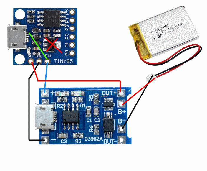
It would be possible to feed the circuit through the USB connector in the charger, but then the opportunity to upload the firmware via the USB connector on the controller board would be lost. It would be possible to leave two USB connectors for various purposes - one for charging, the other for firmware, but this is somehow wrong.
A 6x25x35 battery bought on ebee, but it turned out to be either defective, or I killed it with a short circuit or with a large charge current (the board has a default charging current set to 1A and one resistor needs to be soldered to reduce the current). In any case, when the load was connected, even at 10mA, the voltage on the battery dropped to 1V. At the time of testing, I switched to a half-dead LiPo battery from a small quadcopter. A little later, I ordered the battery from another seller and it turned out to be good.
In principle, this could have stopped, soldered the connecting wires and gently shoved everything into some kind of body, but I decided to measure the consumption of the circuit. And then I shed a tear. Well, that in working condition (when the light bulbs shine to the full), this thing eats up to 130mA, so at rest the consumption is more than 25mA! Those. my 600mAh battery this blinker eats less than a day!
It turned out that about 10mA consume LEDs. Even if they do not glow, the microcontroller still works in each of them and expects a command. Those. You need to come up with a power supply circuit for LEDs.
The remaining 15 mA is consumed by the microcontroller. Yes, it can be put to sleep and according to the datasheet, the consumption will be measured by micro amperes, but in fact it was not possible to get less than 1 mA. I disconnected the ADC and translated the pins into input. There seems to be a leak somewhere in the scheme, but my modest knowledge of electronics is not enough to find and understand it.
Complicate the scheme
Then I remembered that I bought a PT1502 chip for sample. This microcircuit is a lithium battery charge controller complete with a power source with several control inputs. The only difficulty is that the microcircuit goes in a 4x4 mm QFN20 package and requires some strapping. Soldering this at home is difficult, but possible. The fee is difficult for an ordinary LUT and must be ordered from the Chinese. But we are not afraid of difficulties, right?
In a few squares, the scheme can be described as follows.
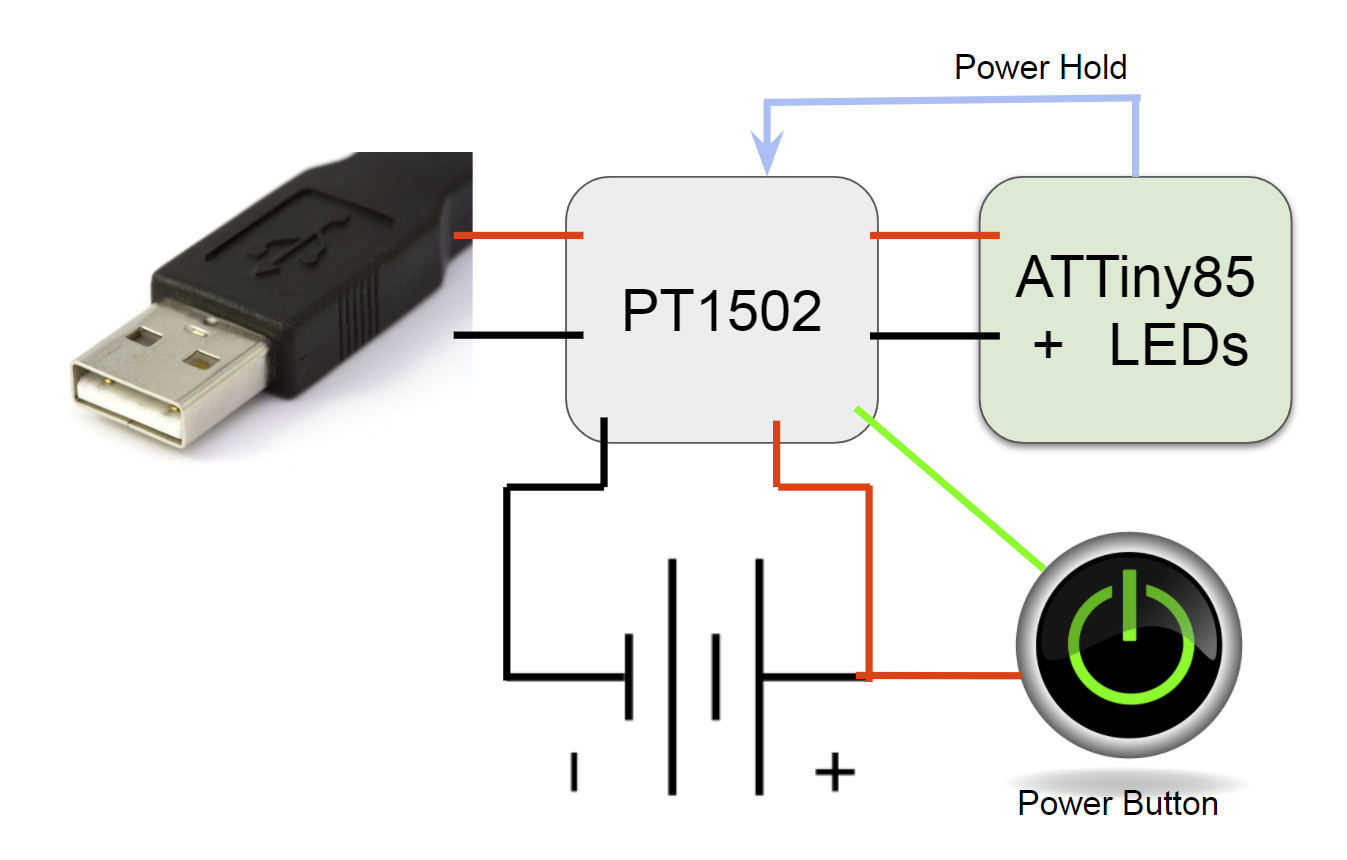
In the off state, the power to the controller and the LEDs is not supplied. The device has a 'Power' button, which turns on the blinker (it also switches modes). The LED shines, say, a minute and if there is no user activity (no one presses a button), then the device turns off. Those. It does not just go to sleep, but it turns off power to itself with the Power Hold signal. And off all at once - and the microcontroller, and LEDs. The power-on and power-off functionality is implemented inside the PT1502 chip.
All that remains is to draw a circuit diagram and make a board. The scheme, for the most part, is lapped from the datasheet PT1502, as well as the Digispark ATTiny85 module. The PT1502 power controller chip is functionally divided into several parts, because the circuit is divided into blocks.
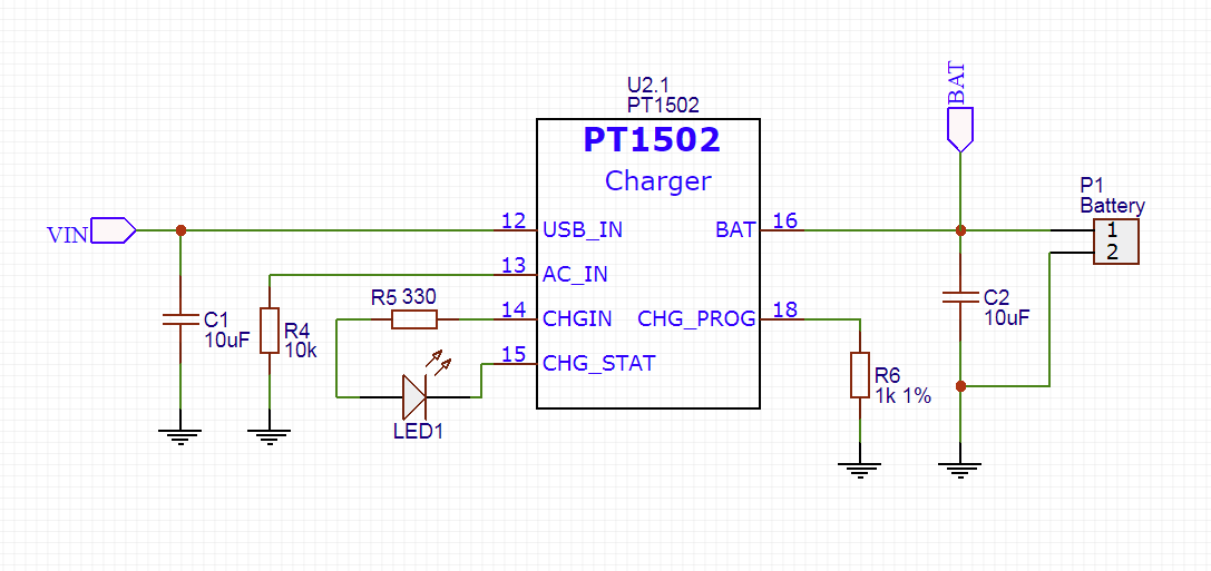
This is, in fact, a lithium battery charge controller with its strapping. LED1 indicates the status of the charge - lit, then the charge is on. Resistor R6 sets the charge current to 470mA. Since I have a 600 mAh battery, in principle it is possible to raise the current and up to 600 mA by setting the resistor to 780-800 Ohm. However, I am not sure about the special quality of my battery - it’s better to charge more slowly, but it will live longer.
Consider the power management scheme.
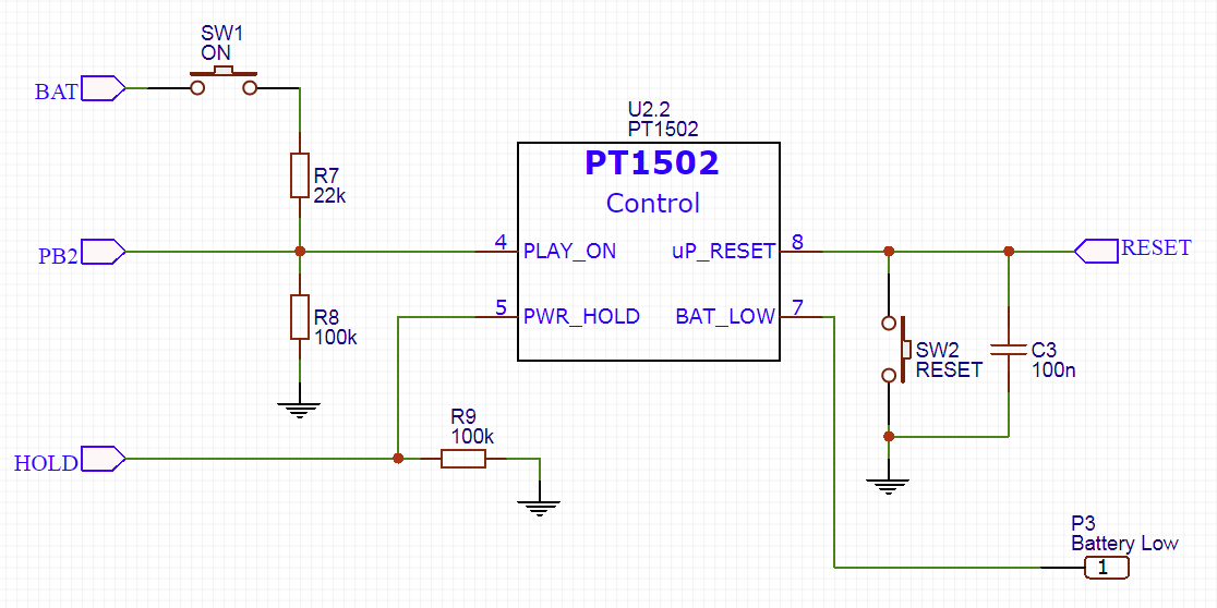
Button SW1 starts the entire system - the PT1502 chip wakes up by itself and then starts all the power sources (there are 3 of them). When the power supply is established, the microcircuit starts the microcontroller by releasing the RESET signal. For the convenience of debugging, I also added a separate Reset button.
The HOLD signal is used to turn off the entire system. When the microcontroller starts, it should put a unit on this line. When it is time to round out, the microcontroller sets a zero to the HOLD line and the PT1502 power supply chip will stop all power supplies.
It would be possible to track the low battery with the help of the BAT_LOW output, but in this work I hammered on it - I do not need to save any data and nothing will explode if I do not notice the dead battery in time. Die so die. But just in case the board provided contact for this case.
Let's return for a second to the SW1 button. I decided not to make 2 separate buttons for switching on and for controlling. Therefore, the same button is also connected to ATTiny85 and during operation switches blinking modes. The values of the divider R7-R8 are chosen so as not to burn the port of the microcontroller PB2. With all voltage ranges of the battery (3.3 - 4.2V), the controller will receive voltage within the limits specified by the datasheet (0.7 * VCC - VCC + 0.5V).
Consider a power source.
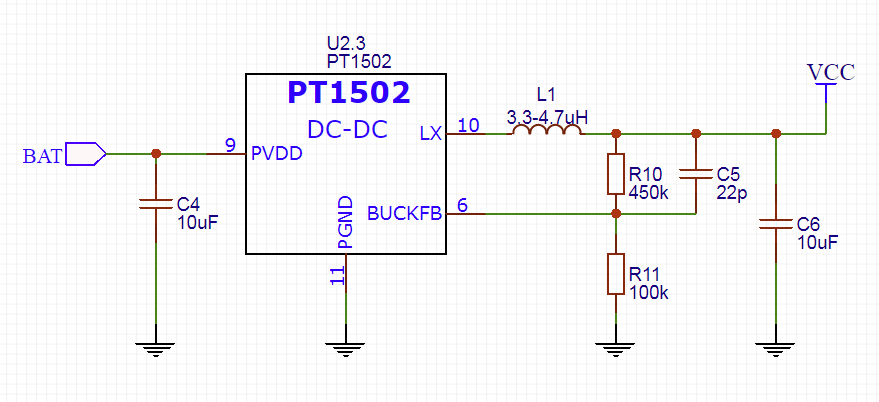
This is a pulsed DC-DC converter. The output voltage is set by resistors R10-R11 and according to the formula from the datasheet is set to 3.3V. Everything else is a simple strapping.
For good, such a sophisticated power supply is not really needed - it would have been possible to power the microcontroller directly from the battery. Simply, this source is already implemented in the PT1502 chip and it can be turned on / off when we need to - why not use this?
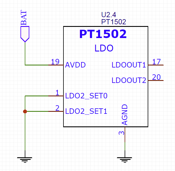
The chip also has 2 linear stabilizers, but I will not use them. Unfortunately, as it turned out, the input voltage to the source is still needed, otherwise the microcircuit thinks that the power supply is still not stable enough and does not start the microcontroller (this knowledge was given to me a week to re-solder the test board to and fro — I could not understand why )
Let us turn to the logical part.
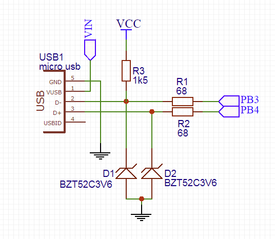
The USB binding is lapped from the Digispark board unchanged. This is needed to match the USB voltages (which run 3.3V) and the microcontroller signals (which in the original is powered by 5V). Since, in my case, the microcontroller is also powered by 3.3V, the circuit could be simplified, but just in case, I spread the original circuit on the board.
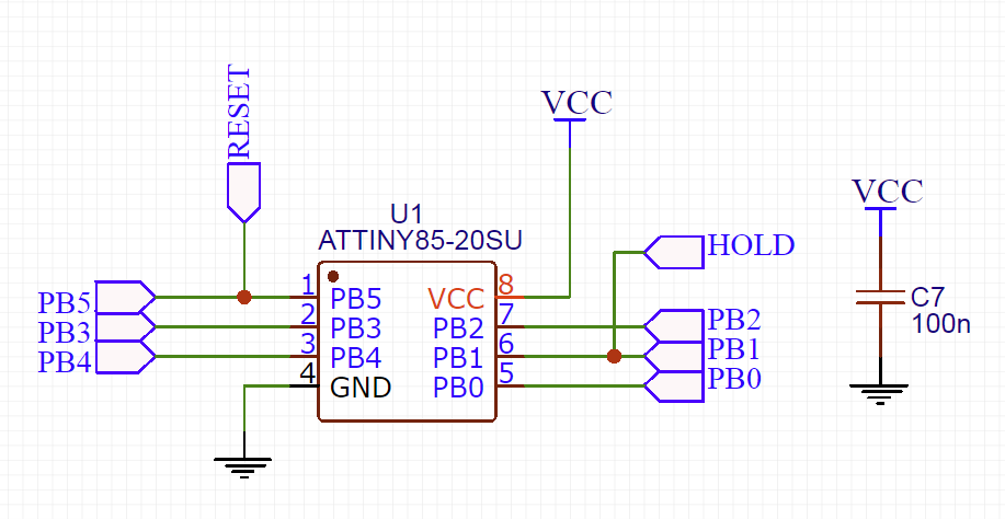
In the strapping of the microcontroller is nothing interesting.
The final touch is a connector.

In fact, I got such a debug board on ATTiny85 with USB support and a lithium battery power controller. Therefore, I didn’t confine myself only to outputting a line to an LED. Instead, I brought all the lines of the microcontroller to a comb - at the same time it is convenient to connect to the programmer as well.
And let almost all the lines are rigidly tied to a specific functionality (PB1 - line Hold, PB2 - power button, PB3 / PB4 - USB, PB5 - Reset) in the future it will be possible to bypass within certain limits. For example, do not unsolder the USB cable and release the PB3 / PB4 lines. Or, for example, refuse to reset and release PB5. In the meantime, only PB0 remains free - connect our LED to it.
Go to the board. Given the limitations on the size of the board at 40x40mm, the number of components and the QFN20 package of the PT1502 chip, I did not even consider making the board at home. Therefore, I immediately began to breed the most compact two-layer board. Here's what I got.
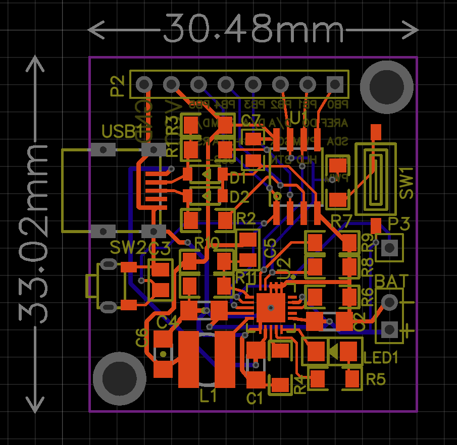
For ease of use, I signed all possible output functions on the reverse side (the idea of slyamsil from the Digispark board)
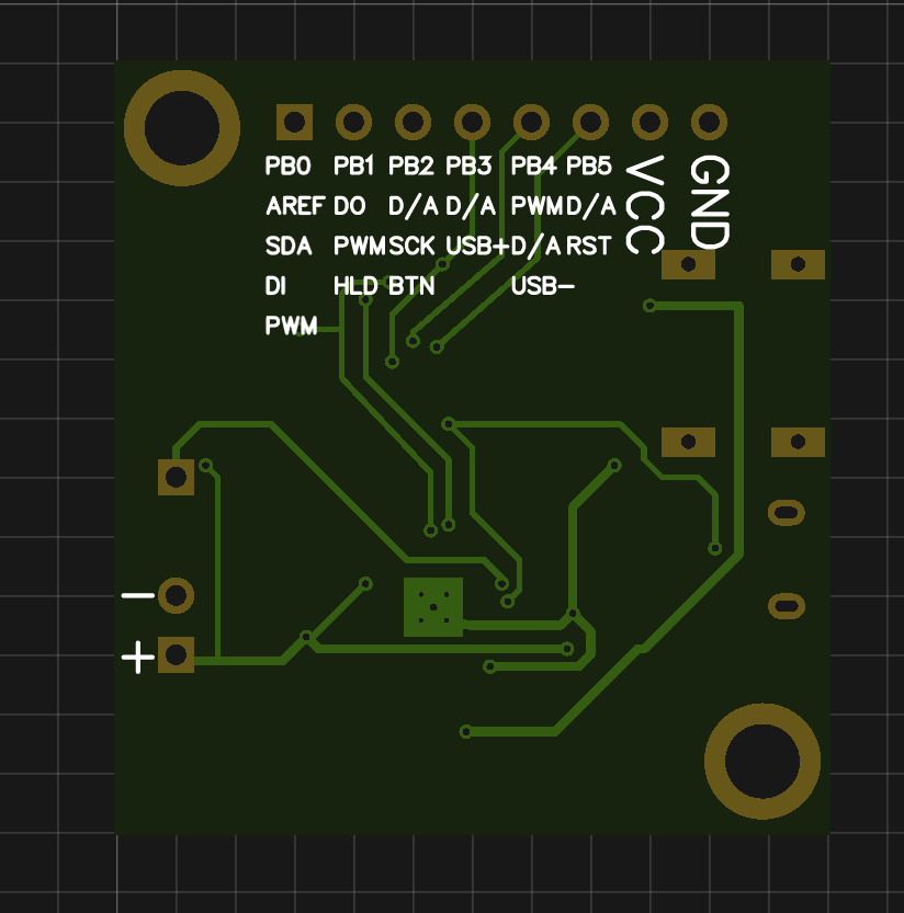
I ordered the board on JLCPCB . I’m not very pleased with the quality, to be honest - if you re-solder a microchip many times, then the mask near the small contacts PT1502 will be a bit crammed. Well, small inscriptions floated a little. However, if everything is soldered from the first time, then the rules.
For soldering QFN20 you will need a soldering dryer, everything else can be soldered with a regular soldering iron with a certain skill. Here is the wired card
Housing
It's time to go to the body. I printed it on a 3D printer. No frills design - box and button. The box has special hooks to install the light into the standard square module of the designer.
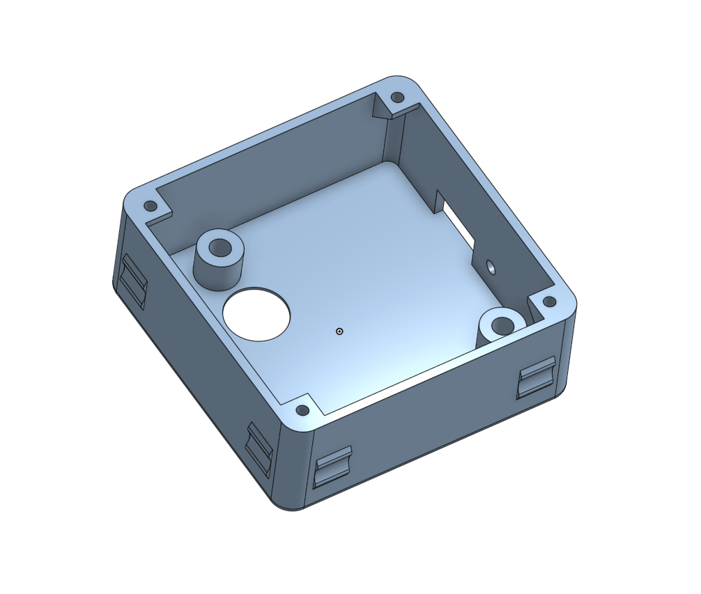
In the case lives the main board and battery.
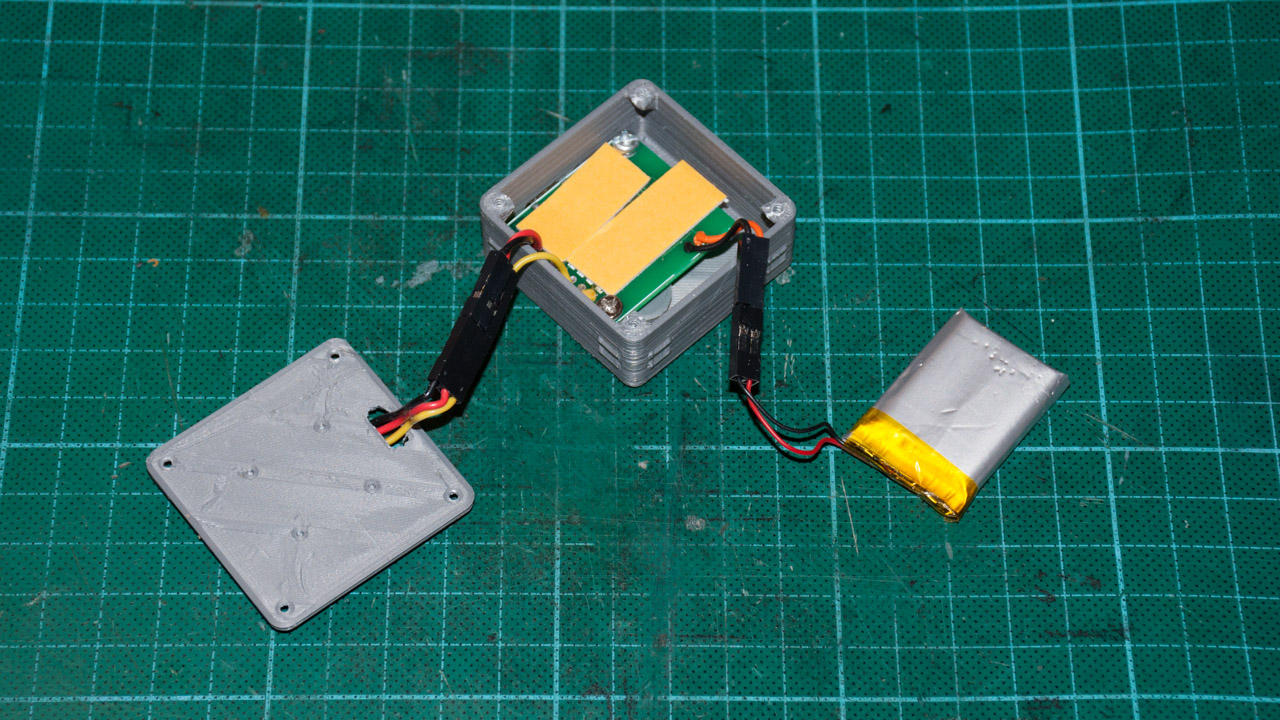
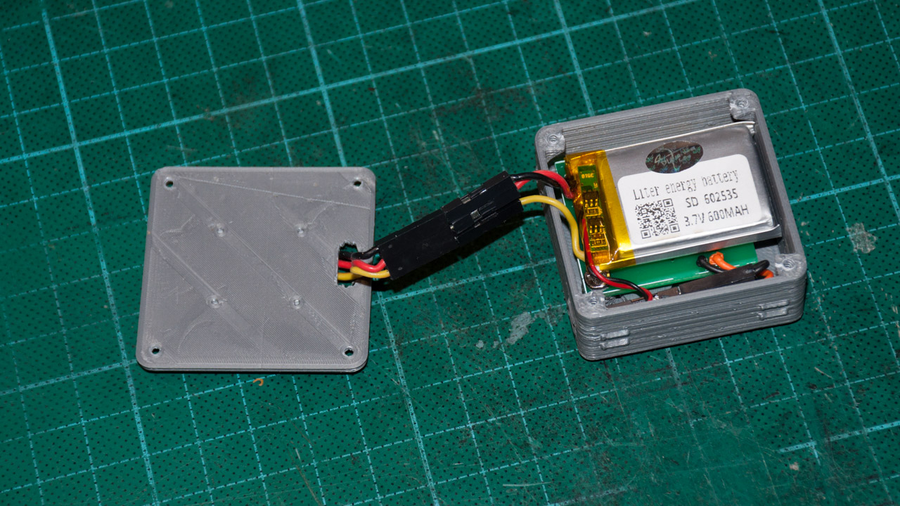
The LED panel is attached to the cover, which in turn is screwed to the main box.
At first, I thought to fasten the LED panel to the cover with screws, but in the end I just stuck it on a double-sided tape. It turned out like this
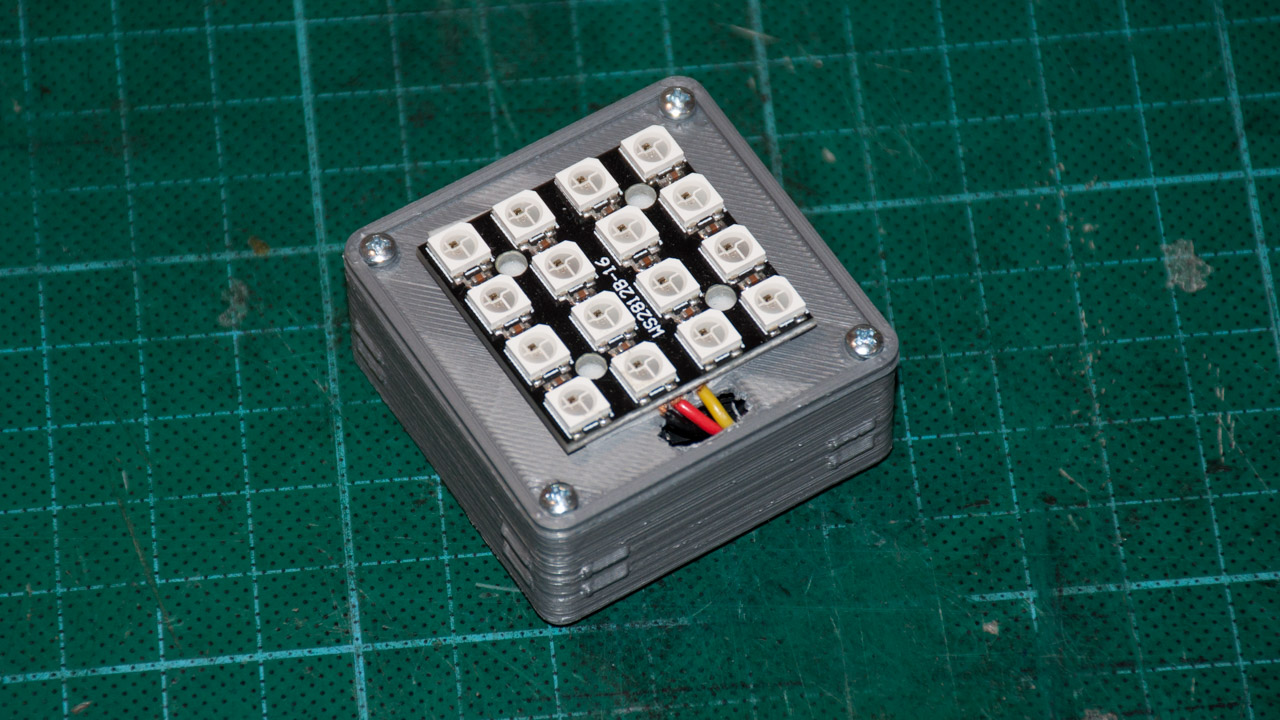
In this form, the device can already be used, but it still looks ugly - there is not enough lens.
I tried to make the first version of the diffuser using the technology of shrinking PET bottles with a building dryer (peeped from model airplanes).
So, first you need a blank. I made it from plaster, which I filled in the form, which I printed on a 3D printer. In the first embodiment, the form was one-piece and I could not pull the cast disc out of it. Therefore it was necessary to make a form of two parts.
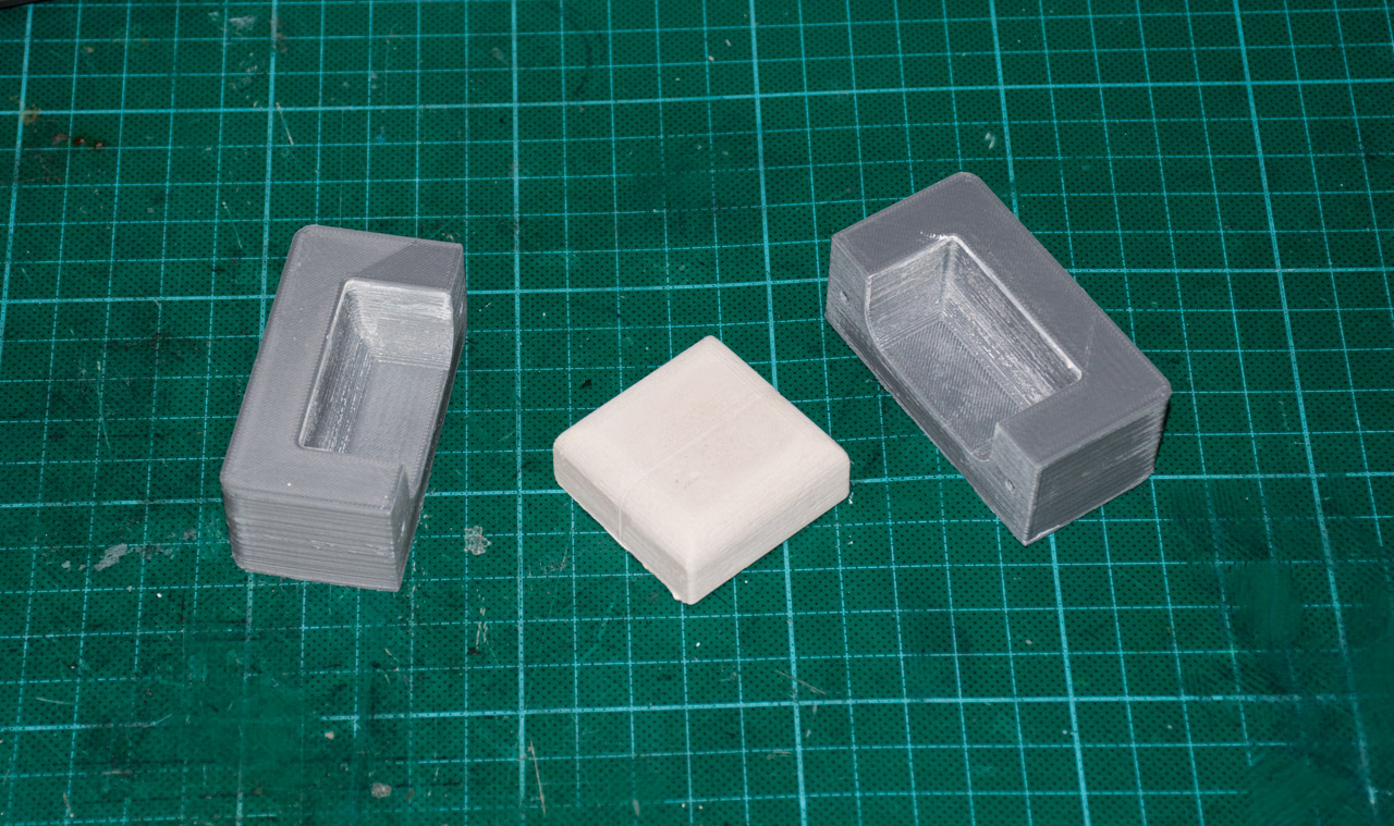
The idea of the method is as follows. You put a bottle of baby yogurt on the disc and set it down with a building dryer. Here are just rewashing the pieces of 20 different containers from under the different jelly, I never managed to sit this thing nicely, without folds and bubbles. Apparently you need to fence some kind of vacuum installation and shrink sheet plastic. In general, it was too difficult for such crafts.
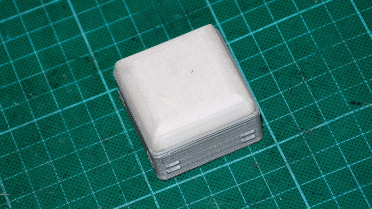
Rummaging through the bottom of the barrel, I found a plastic Verbatim PET Transparent probe in a couple of meters. I decided to try the diffuser just to print. And although at the entrance to the plastic printer seems crystal clear, the real detail turns out to be dull dull. This is probably due to the internal structure, since the layers do not fill the volume completely but overlap at intervals and slots. Moreover, if you try to process the part with sandpaper for a smoother surface, you will get even more matting. However, this is exactly what I needed.
I was too lazy to mess with the mount for the diffuser, so I attached it to the hot melt glue. So I now conditionally collapsible design. I could have been confused with the invention of some snaps, but I already had a transparent plastic probe. So let it be hot melt.

Firmware
For the LED blinker, it is not necessary to dive very strongly into the periphery of the microcontroller - just a couple of functions for working with GPIO. But since the module fits into the Arduino platform, why not use it?
First, a few definitions and constants
// Number of total LEDs on the board. Mine has 4x4 LEDs#define NUM_HW_PIXELS 16// Pin number where LED data pin is attached#define DATA_PIN 0// Pin number where mode switch button is attached#define BUTTON_PIN 2// Power Enabled pin#define POWER_EN_PIN 1// Max brightness (dimming the light for debugging)#define MAX_VAL 255Here we determine the number of pixels in my matrix, the pin numbers and the maximum brightness of the LEDs (during debugging it was convenient to set it to 50, so as not to blinded the eyes) The
LEDs in my matrix are arranged in a rather non-obvious way - zigzag. Because for different effects had to be renumbered.
// LED indexes for different patternsuint8_t circleLEDIndexes[] = {0, 1, 2, 3, 4, 11, 12, 13, 14, 15, 8, 7};
uint8_t beaconLEDIndexes[] = {6, 5, 10, 9};
uint8_t policeLEDIndexes[] = {7, 6, 10, 11, 4, 5, 9, 8};
To control the LEDs, I did not reinvent the wheel and took a ready-made library for working with WS8211 LEDs . The library interface is slightly whitened-colored. Some auxiliary functions (for example, converting HSV to RGB) also come from there.
First, the WS8211 board and library need to be initialized.
// Driver
Ai_WS2811 ws2811;
voidsetup(){
    // Set up power
    pinMode(POWER_EN_PIN, OUTPUT);
    digitalWrite(POWER_EN_PIN, HIGH);
    // initialize LED data pin
    pinMode(LED_PIN, OUTPUT);
    // Initialize button pin
    pinMode(BUTTON_PIN, INPUT);
    // Initialize WS8211 librarystatic CRGB ledsBuf[NUM_HW_PIXELS];
    ws2811.init(DATA_PIN, NUM_HW_PIXELS, ledsBuf);
    // Set the watchdog timer to 2 sec
    wdt_enable(WDTO_2S);
}
First of all, you need to set the POWER HOLD signal to one - it will be a signal from the PT1502 chip, that the microcontroller has started up and is working properly. The microcircuit in turn will regularly supply electricity to the microcontroller and the LEDs as long as the HOLD signal is set to one.
Next, the LED output control legs and the input buttons are configured. You can then initialize the WS8211 library.
Since this is a fairly self-contained device, the microcontroller should not be allowed to stick in an incomprehensible state and gobble up the entire battery. To do this, I start the watchdog timer for 2 seconds. The timer will restart in the main program loop.
Now we need to define a couple of auxiliary functions. The WS8211 library stores a buffer with the color values of each LED. Work with the buffer directly is not very convenient, because I wrote a simple function to write RGB values to a specific LED
voidsetRgb(uint8_t led_idx, uint8_t r, uint8_t g, uint8_t b){
    CRGB * leds = ws2811.getRGBData();
    leds[led_idx].r = r;
    leds[led_idx].g = g;
    leds[led_idx].b = b;
}
But in most cases in the RGB color model it is not very convenient to count colors, if not impossible. For example, when drawing all sorts of rainbows, it is more convenient to work with the HSV color model . The color of each pixel is set by the color tone value and brightness. Saturation value is omitted for simplicity (maximum is used). The hue values are reduced to the range of 0-255 (instead of the standard 0-359).
/**
* HVS to RGB conversion (simplified to the range 0-255)
**/voidsetHue(uint8_t led_idx, int hue, int brightness){
	//this is the algorithm to convert from RGB to HSVdouble r = 0;
	double g = 0;
	double b = 0;
	double hf = hue/42.6; // Not /60 as range is _not_ 0-360int i=(int)floor(hue/42.6);
	double f = hue/42.6 - i;
	double qv = 1 - f;
	double tv = f;
	switch (i)
	{
		case0:
			r = 1;
			g = tv;
			break;
		case1:
			r = qv;
			g = 1;
			break;
		case2:
			g = 1;
			b = tv;
			break;
		case3:
			g = qv;
			b = 1;
			break;
		case4:
			r = tv;
			b = 1;
			break;
		case5:
			r = 1;
			b = qv;
			break;
	}
    brightness = constrain(brightness, 0, MAX_VAL);
    setRgb(led_idx,
        constrain(brightness*r, 0, MAX_VAL),
        constrain(brightness*g, 0, MAX_VAL),
        constrain(brightness*b, 0, MAX_VAL)
    );
}
The function is taken from the library Ai_WS8211 and slightly filed. In the original version of this function from the library there were a couple of bugs because of what the color on the rainbows appeared with jerks.
Let us turn to the implementation of various effects. Each function is called from the main loop to draw one “frame”. As each effect operates with different parameters between calls, they are stored in static variables.
This is the simplest effect - all LEDs are filled with one color that changes smoothly.
voidrainbow(){
    staticuint8_t hue = 0;
    hue++;
    for (int led = 0; led < NUM_HW_PIXELS; led++)
        setHue(led, hue, MAX_VAL);
    ws2811.sendLedData();
    delay(80);
}
The next effect is more interesting - it displays a rainbow along the contour of the matrix, and the colors in the rainbow gradually shift in a circle.
voidslidingRainbow(){
    staticuint8_t pos = 0;
    pos++;
    for (int led = 0; led < ARRAY_SIZE(circleLEDIndexes); led++)
    {
        int hue = (pos + led*256/ARRAY_SIZE(circleLEDIndexes)) % 256;
        setHue(circleLEDIndexes[led], hue, MAX_VAL);
    }
    ws2811.sendLedData();
    delay(10);
}
And this effect fills the entire matrix with a random color, which at first smoothly lights up, and then also goes out smoothly.
voidrandomColorsFadeInOut(){
    staticuint8_t color = 0;
    staticbool goesUp = false;
    staticuint8_t curLevel = 0;
    if(curLevel == 0 && !goesUp)
    {
        color = rand() % 256;
        goesUp = true;
    }
    if(curLevel == MAX_VAL && goesUp)
    {
        goesUp = false;
    }
    for(int led = 0; led < NUM_HW_PIXELS; led++)
        setHue(led, color, curLevel);
    if(goesUp)
        curLevel++;
    else
        curLevel--;
    ws2811.sendLedData();
    delay(10);
}
The next group of effects draws various flashing lights. For example, a child likes to build a bulldozer from magnets and an orange flasher will be very useful there.
voidorangeBeacon(){
    constint ORANGE_HUE = 17;
    staticuint8_t pos = 0;
    pos+=3;
    for (int led = 0; led < ARRAY_SIZE(circleLEDIndexes); led++)
    {
        int brightness = brightnessByPos(pos, led*255/ARRAY_SIZE(circleLEDIndexes), 70);
        setHue(circleLEDIndexes[led], ORANGE_HUE, brightness);
    }
    ws2811.sendLedData();
    delay(1);
}
Technically, the effect looks like a bright dot that moves across the matrix. But to make the neighboring LEDs look beautiful, they gradually fade away as they move away from the main point. Therefore, I needed a function that calculates this very brightness.
intbrightnessByPos(int pos, int ledPos, int delta){
    int diff = abs(pos - ledPos);
    if(diff > 127)
        diff = abs(256-diff);
    int brightness = MAX_VAL - constrain(MAX_VAL*diff/delta, 0, MAX_VAL);
    return brightness;
}
Pos is a certain conditional position of the luminous point brightness, displayed on the looped range of 0-255. ledPos is the position of the LED (displayed on the same range) whose brightness you want to calculate. If the position difference is greater than delta, then the LED is off, and the closer to the position, the brighter it lights up.
Or, for example, a red and blue flashing beacon
voidpoliceBeacon(){
    constint RED_HUE = 0;
    constint BLUE_HUE = 170;
    staticuint8_t pos = 0;
    pos += 2;
    for (int led = 0; led < ARRAY_SIZE(policeLEDIndexes); led++)
    {
        int ledPos = led*255/ARRAY_SIZE(policeLEDIndexes);
        int brightness = brightnessByPos(pos, ledPos, 50);
        setHue(policeLEDIndexes[led], RED_HUE, brightness);
        if(brightness == 0)
        {
            brightness = brightnessByPos((pos+100) % 256, ledPos, 50);
            setHue(policeLEDIndexes[led], BLUE_HUE, brightness);
        }
    }
    ws2811.sendLedData();
    delay(1);
}
If we are talking about cars, then the traffic light is not a problem here.
These are features that include different traffic lights at different positions.
voidclearPixels(){
    for(int i=0; i<NUM_HW_PIXELS; i++)
    {
        setRgb(i, 0, 0, 0);
    }
}
voidredTrafficLights(){
    for(int i=0; i<4; i++)
        setRgb(i, MAX_VAL, 0, 0);
    ws2811.sendLedData();
}
voidyellowTrafficLights(){
    for(int i=4; i<8; i++)
        setRgb(i, MAX_VAL, MAX_VAL, 0);
    ws2811.sendLedData();
}
voidgreenTrafficLights(){
    for(int i=8; i<16; i++)
        setRgb(i, 0, MAX_VAL, 0);
    ws2811.sendLedData();
}
It's time to revive. The traffic light is working on a special program, set in something like bytecode. The plate describes the mode and the time for which this mode should be included.
enum TRAFFIC_LIGHTS
{
    NONE, RED, YELLOW, GREEN
};
structtrafficLightState
{uint8_t state;
    uint16_t duration;
};
const trafficLightState trafficLightStates[] = {
    {NONE, 1},         // clear yellow
    {RED, 7000},     // red
    {YELLOW, 2000},      // red + yellow
    {NONE, 1},         // clear red+yellow
    {GREEN, 7000},     // green
    {NONE, 300},       // Blinking green
    {GREEN, 300},       // Blinking green
    {NONE, 300},       // Blinking green
    {GREEN, 300},       // Blinking green
    {NONE, 300},       // Blinking green
    {GREEN, 300},       // Blinking green
    {NONE, 1},         // clear green
    {YELLOW, 2000},      // yellow
};
Actually the function that handles it all
voidtrafficLights(){
    staticuint8_t curStateIdx = 0;
    staticunsignedlong curStateTimeStamp = 0;
    // Switch to a new state when time comesif(millis() - curStateTimeStamp > (unsignedlong)trafficLightStates[curStateIdx].duration)
    {
        curStateIdx++;
        curStateIdx %= ARRAY_SIZE(trafficLightStates);
        curStateTimeStamp = millis();
    }
    switch(trafficLightStates[curStateIdx].state)
    {
        case NONE:
            clearPixels();
            ws2811.sendLedData();
            break;
        case RED:
            redTrafficLights();
            break;
        case YELLOW:
            yellowTrafficLights();
            break;
        case GREEN:
            greenTrafficLights();
            break;
        default:
            break;
    }
    // Just waiting
    delay(10);
}
Upon reaching the specified time interval, the next traffic light mode is turned on and the time starts again.
The last effect for which my imagination was enough is the stars. 5 random LEDs light up at random brightness and then fade out. If one star goes out, the other will light up in a random place.
voidstars(){
    constuint8_t numleds = 5;
    staticuint8_t ledIndexes[numleds] = {0};
    staticuint8_t curVal[numleds] = {0};
    staticuint8_t maxVal[numleds] = {0};
    for(int i=0; i<numleds; i++)
    {
        if(ledIndexes[i] == 0)
        {
            uint8_t led = rand() % (NUM_HW_PIXELS+1);
            CRGB * leds = ws2811.getRGBData();
            if(leds[led].r == 0)
            {
                ledIndexes[i] = led;
                maxVal[i] = rand() % (MAX_VAL-1) + 1;
                curVal[i] = 0;
            }
        }
        else
        {
            uint8_t led = ledIndexes[i];
            if(curVal[i] < maxVal[i])
                curVal[i]++;
            elseif(curVal[i] == maxVal[i])
                maxVal[i] = 0;
            elseif(curVal[i] == 0 || --curVal[i] == 0)
                ledIndexes[i] = 0;
            setRgb(led-1, curVal[i], curVal[i], curVal[i]);
        }
    }
    ws2811.sendLedData();
    delay(80);
}
Somewhere here the malicious bug crept in. Sometimes the asterisks light up sharply, or vice versa go out sharply. But honestly, I was too lazy to deal with it - it looks quite normal.
It's time to think about saving battery. I have already given the values of consumption of this whole thing. If you do not think about turning off the power, the LEDs will eat the battery in a couple of hours. This function deals with power outages after 90 seconds of inactivity. Initially it was 60 seconds, but with a real game, this was not enough, and 2 minutes was somehow long.
voidshutdownOnTimeOut(bool resetTimer = false){
    staticunsignedlong periodStartTime = 0;
    if(periodStartTime == 0 || resetTimer)
    {
        periodStartTime = millis();
        return;
    }
    if(millis() - periodStartTime >= 90000UL)
    {
        periodStartTime = 0;
        shutDown();
    }
}
Actually power off occurs so.
voidshutDown(){
    clearPixels();
    ws2811.sendLedData();
    wdt_disable();
    digitalWrite(POWER_EN_PIN, LOW);
    // No power after this pointwhile(true)
        ;
}
If the user presses the buttons, then the timer is reset. After the set time has elapsed, the function sets the HOLD signal to zero, which is the PT1502 command to turn off the power. Watchdog, by the way, also needs to be stopped, otherwise after 2 seconds it will wake up the system and turn on the power again.
Finally, the main loop that starts it all
// List of pointers to functions that serve different modesvoid (*Modes[])() =
{
    rainbow,
    slidingRainbow,
    orangeBeacon,
    policeBeacon,
    trafficLights,
    stars,
    randomColorsFadeInOut
};
voidloop(){
    staticuint8_t mode = eeprom_read_byte( (uint8_t*) 10 );
    staticbool waitingForBtnUp = false;
    staticlong btnPressTimeStamp;
    // Button switches modeif(digitalRead(BUTTON_PIN) == HIGH && !waitingForBtnUp)
    {
        delay(20);
        if(digitalRead(BUTTON_PIN) == HIGH)
        {
            mode++;
            mode %= ARRAY_SIZE(Modes); // num modes
            clearPixels();
            ws2811.sendLedData();
            delay(1);
            eeprom_write_byte( (uint8_t*) 10, mode );
            waitingForBtnUp = true;
            btnPressTimeStamp = millis();
            shutdownOnTimeOut(true);
        }
    }
    // Shut down on long press over 5sif(digitalRead(BUTTON_PIN) == HIGH && waitingForBtnUp && millis() - btnPressTimeStamp > 5000)
        shutDown();
    // Detect button releaseif(digitalRead(BUTTON_PIN) == LOW && waitingForBtnUp)
        waitingForBtnUp = false;
    // display LEDs according to current mode
    Modes[mode]();
    // pong shutdown timer
    shutdownOnTimeOut();
    // Yes, we still alive
    wdt_reset();
}
Pressing the button toggles modes and resets the auto off timer. Depending on the current mode, one of the effect functions from the Modes list is launched. The watchdog is also reset on each cycle.
If a child, say, played in a police car and after 1.5 minutes the flasher turned off, then most likely after re-switching on the son will want to continue playing in the police car. For this, the selected mode is stored in the EEPROM (cell number 10 is selected from the balda).
Here is a video that shows how it all works.
Bootloader
Almost everything is ready. But there is one more thing that needs to be filed - a bootloader. The fact is that the standard bootloader does not suit us.
Firstly, when the power is turned on, it waits for as much as 6 seconds - perhaps the firmware will be poured into it. Only after this control is transferred to the main firmware. This is convenient at the development stage, but will be annoying in the finished device.
And secondly, the standard bootloader does not know anything about the PT1502 chip, which would be nice to send the HOLD signal. Without this signal, the microcircuit thinks that the microcontroller either did not start, or, on the contrary, wants to switch off. And if so, then in a few milliseconds PT1502 will cut off the power to the entire circuit.
The blessing to fix both problems is not difficult. The digispark ATTiny85 board uses a micronucleus loader.. This bootloader is just enough to file for our needs. It is only necessary to correct the corresponding defines in the configuration file.
First of all, I copied the standard firmware \ configuration \ t85_default configuration into my own directory and already made all the changes in it. So it will be in which case it is easy to roll back to the original bootloader.
In the bootloaderconfig.h file there is a choice of the way to enter the bootloader. From what is offered out of the box, nothing suits us, but the closest option is ENTRY_JUMPER. In this embodiment, the entrance to the loader occurs only if a certain level appears on a certain pin (a jumper is closed on the board).
#define ENTRYMODE ENTRY_JUMPERWe do not have a jumper, but there is a button on the leg of PB2. Let the entrance to the bootloader occur if the power button is held for 5-7 seconds when the power is turned on. But if you press and release, then the transition to the main firmware occurs immediately.
We need to define 3 functions - initialization, deinitialization and actually checking, and whether it is time to enter the bootloader. In the original, they are all simple and implemented by macros. We will only be simple the first 2
#define HOLD_PIN PB1#define JUMPER_PIN PB2#define JUMPER_PORT PORTB #define JUMPER_DDR DDRB #define JUMPER_INP PINB #define bootLoaderInit() {JUMPER_DDR &= ~_BV(JUMPER_PIN); JUMPER_DDR |= _BV(HOLD_PIN); JUMPER_PORT &= ~_BV(JUMPER_PIN); JUMPER_PORT |= _BV(HOLD_PIN); _delay_ms(1);}#define bootLoaderExit() {;}bootLoaderInit () sets the pin of the button (JUMPER_PIN) to the input and turns off the suspender on it. We already have a suspender on the board, and to the ground, and when we press the button on the pin, the opposite will be one. At the same time, you can immediately configure the HOLD signal to output and put a unit on it ...
For an explanation of bit arithmetic, go, for example, here , and an understanding of the GPIO settings registers in AVR controllers can be learned, for example, from here .
The bootLoaderExit () function is empty, since the set configuration is quite suitable for the subsequent transition to the main firmware.
The bootLoaderStartCondition () function that is responsible for entering the bootloader into the macro format has not climbed, and therefore has become a full feature
#ifndef __ASSEMBLER__// Bootloader condition is to hold the button for 5 secondsinlineunsignedcharbootLoaderStartCondition(){
  longint i;
  for(i=0; i<10000000; i++)
    if( !(JUMPER_INP & _BV(JUMPER_PIN)))
      return0;
  return1;
}
#endif
The function for a few seconds (in fact about 6-7) checks the status of the button. If the button was released earlier, then we do not need to enter the bootloader. Patient and persistent are allowed on to the bootloader.
As it turned out, the bootloaderconfig.h file participates in the compilation of assembler files and the code in this file causes errors. I had to put the function in the block #ifndef __ASSEMBLER__
Another parameter that I corrected, tells the bootloader what to do if it was not connected to USB - to exit after one second. The fact is that during the break-in, the son often pressed the button and inadvertently entered the bootloader. I don’t know how miraculously, but if the bootloader didn’t see the USB connection, it could randomly overwrite some pages of memory. Therefore, if there is no connection, we will simply go to the main program.
/*
 * Define bootloader timeout value.
 *
 *  The bootloader will only time out if a user program was loaded.
 *
 *  AUTO_EXIT_NO_USB_MS        The bootloader will exit after this delay if no USB is connected.
 *                             Set to 0 to disable
 *                             Adds ~6 bytes.
 *                             (This will wait for an USB SE0 reset from the host)
 *
 *  All values are approx. in milliseconds
 */#define AUTO_EXIT_NO_USB_MS    1000
We compile ... and we get an error that the code does not fit into the bootloader space allocated to it. Since the flash memory in the controller is very small, the bootloader is squeezed to the maximum to leave more space for the main program. But this is easily fixed in the Makefile.inc file following the instructions.
# hexadecimal address for bootloader section to begin. To calculate the best value:# - make clean; make main.hex; ### output will list data: 2124 (or something like that)# - for the size of your device (8kb = 1024 * 8 = 8192) subtract above value 2124... = 6068# - How many pages in is that? 6068 / 64 (tiny85 page size in bytes) = 94.8125# - round that down to 94 - our new bootloader address is 94 * 64 = 6016, in hex = 1780
BOOTLOADER_ADDRESS = 1940
Then I just reduced the starting address of the bootloader one page (64 bytes), thereby increasing the space for the bootloader.
For the rest, compiling and uploading a bootloader using the USBAsp programmer was not a problem.
Conclusion
It was a very interesting way from the prototype on the breadboard to the finished device. It seems to look like an ordinary twinkler from a lesson on arduine, but in fact in the process of work I had to solve a whole bunch of interesting problems - here both the fight against consumption, and the choice of the element base, and the design of the case, and bringing to mind the firmware with the bootloader. I sincerely hope that my experience will be useful to someone.
Could it have been easier? Sure you may. I think everything could be done with a transistor. Unfortunately, here is this article.I read it after soldering the board. I would have seen the article earlier - I would have done everything on the very same TP4056 - it is easier to solder it. Anyway, the DC-DC converter inside PT1502 is not needed for this device. However, a practical study of the PT1502 chip is useful for my other project, as well as the ability to solder the chips in the QFN20 package.
Finally, here are the links to my project:
Firmware code
Scheme and board
Case model and diffuser
Ready STL models for printing
