February 20, 2018 at 02:13
"Hello, Habr" at a frequency of 835 kHz
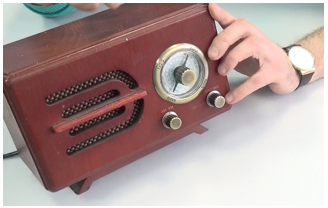 Once a thought arose in my head, but what would be done to cross an old radio in a wooden case and a modern controller for the Internet of things ESP32? Either something is wrong with my head, or I have nothing to do, but I managed to cross it. Not stereotyped, in general, although judging you, dear readers of Habr).
 I ask for details under cat.
32> 8266
In mathematics, this is absurd, but in our case it is. The functionality and capabilities of the ESP32 are much larger than the ESP8266. In addition to a large number of GPIOs, the microcontroller is more powerful functionally, bluetooth has been added to the standard Wi-fi, and the most correct one in my opinion is the presence of two channels of digital-to-analog conversion (DAC in our opinion is DAC in import). Therefore, it’s nothing complicated (without resorting to various tricks) to directly force the controller to be a generator of various signals or even speak a human language. It is this DAC that we need.
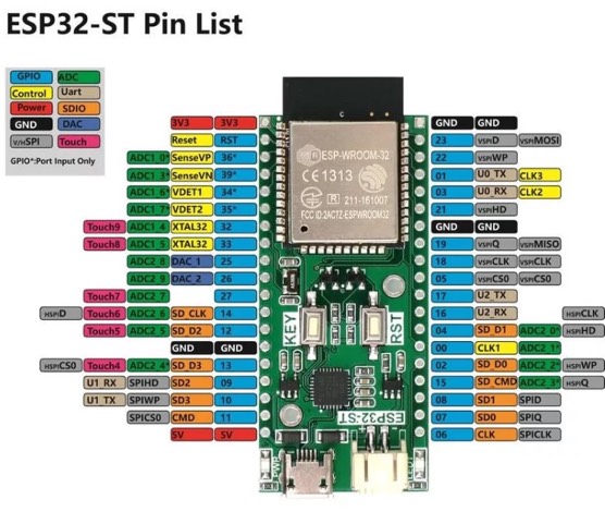
The controller has 2 DAC channels on 25 and 26 pins. As I understand it, this is in order to even cut stereo sound if necessary. There is a lot of information about the ESP32 controller that can be taken here or here , and for fans of technical documentation, here is a link to the datasheet. In my case, there was a WEMOS series developer’s handkerchief with a small screen on board, which in itself is quite convenient - you can immediately debug it with displaying information on the spot or display some data.
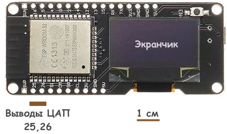
A convenient thing in general, although the price could be more modest. Bought here .
Get to the point!
Having the DAC on board, we can simulate a “pure” sinusoidal signal of a certain frequency. Analysis of the datasheet showed that the sampling frequency of the DACs of the ESP32 controller can reach about 13 MHz, so we need to understand what sine frequency we can get in this case. To do this, it is necessary to approximate the sine by a certain number of time reports - the more reports to take, the better the signal will look, but the limiting frequency that can be obtained in the end will decrease. In this case, the signal amplitude is limited by the DAC capacity and is 8 bits.

It will not be enough to approximate the sine with four or eight temporary reports, but 16 will do just fine.
int sintab[] = {0, 48, 90, 117, 127, 117, 90, 48, 0, -48, -90, -117, -127, -117, -90, -48};
Of course, it would be better to take 32 or 64 reports, but then the frequency of the final signal drops significantly. Thus, when sampling in 16 time reports and a limit range of the DAC operation of 13 MHz, you can get a wow such a sine with a frequency of about 800 kHz (13 MHz / 16 bit). But this already falls into the medium wave range of household radios, to which it will be possible to transmit a useful signal, for example, speech. The scheme is terribly simple. Does not need to be configured)

To the terminal 25 of the DAC, we connect a piece of wire (40 centimeters), which acts as an antenna. The radio transmitter is almost ready!
Amplitude modulation
Having received a stable carrier frequency is still not enough to realize the transmission of a useful signal to a radio receiver. It is necessary to modulate the carrier frequency with a useful low-frequency signal, for example, human speech or music, implementing the so-called amplitude modulation .

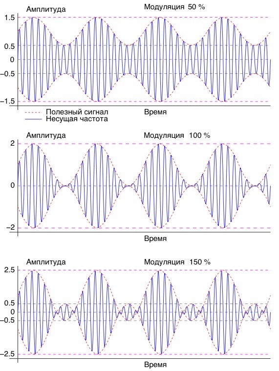
We must change the amplitude of the carrier frequency (above) with an information signal (in the center), providing an acceptable modulation depth , which ideally should be 1 (or 100%), i.e. the final signal (bottom) is a high-frequency signal that constantly changes in amplitude. Since it is not always possible to realize the modulation depth clearly at 100 percent, a level of 50 percent is already quite acceptable (approximately as in the figure). The sound quality will be slightly worse, but it does not matter.
Hello, Habr!
Now our task is to record an audio file in any sound editor to get a sound file, which we will broadcast on a frequency of about 800 kHz and receive on our radio.

This is the phrase "Hello, Habr, frequency 835 kHz." From this file we need to generate an information signal report file, which can be converted using this link . The structure of the final output file will be something like this
const unsigned int sampleRate = 44100; // столько отчетов идет в секунду
const unsigned int sampleCount = 289728;
// всего отчетов в звуковом файле. Поделив это на 44100 получаем длину аудифайла. Получается чуть больше 6 сек.
const signed char samples[] = {
-2, -4, -7, -10, -12, -13, -13, -14, -13, -12, -11, -11, -9, -8, -6, -5,
-4, -2, -2, -3, -4, -6, -10, -15, -21, -27, -34, -39, -41, -40, -38, -34,
-28, -22, -19, -15, -13, -13, -16, -18, -21, -24, -27, -29, -31, -33, -35, -36,
-36, -37, -38, -39, -38, -37, -36, -33, -31, -30, -30, -31, -32, -34, -35, -35,
-35, -35, -34, -34, -33, -32, -31, -31, -31, -31, -31, -31, -29, -27, -25, -22,
......
и еще много много много цифр
......
-20, -18, -16, -14, -13, -11, -9, -8, -7, -6, -5, -4, -3, -3, -2, -1,
0, 2, 6, 10, 14, 19, 23, 27, 28, 28, 26, 24, 21, 20, 20, 21,
23, 25, 28, 30, 32, 34, 36, 37, 38, 39, 40, 41, 41, 42, 43, 43,
42, 40, 38, 36, 35, 36, 38, 40, 42, 43, 43, 42, 39, 37, 34, 31,
30, 29, 30, 31, 32, 33, 33, 32, 29, 26, 22, 19, 17, 15, 14, 15};
This is essentially an array of amplitudes of the useful signal, which, roughly speaking, we add (if greater than zero) or subtract (if the value is less than zero) from the amplitudes of the high-frequency signal, thereby realizing the amplitude modulation we need.
It remains only to fill in the firmware, connect a piece of wire to the 25th pin in the form of an antenna and, transferring the receiver to the AM range, tune to a frequency in the region of 800-850 kHz.
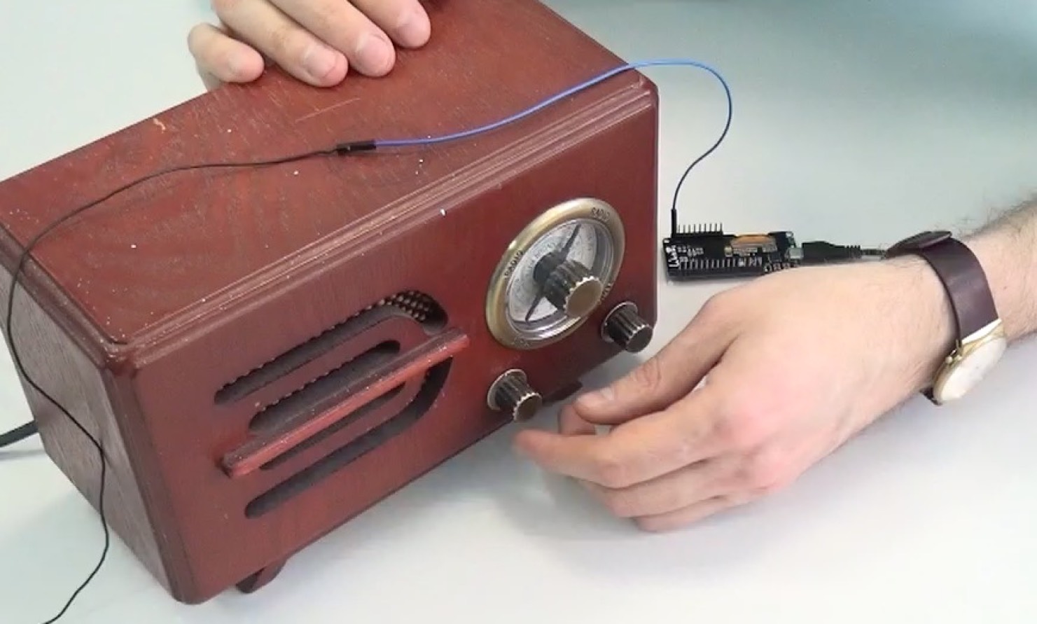
The transmitter power, of course, is scanty. Therefore, the antenna is located very close to the receiver.
Actually the final code of the program takes 70 lines. The converted audio file as sample.h report file can be downloaded here . It is important not to forget to drop this file into the same folder in which the program itself is located.
Program code
Stitched and compiled in the ARDUINO IDE. How to make friends ESP32 with him, read, for example, here . Read more about the source code used in the project here .
//подключаем аудиофайл отдельным модулем
#include "sample.h"
#include
#include "driver/i2s.h"
static const i2s_port_t i2s_num = (i2s_port_t)I2S_NUM_0; // i2s
//настроим параметры i2s
static const i2s_config_t i2s_config = {
     .mode = (i2s_mode_t)(I2S_MODE_MASTER | I2S_MODE_TX | I2S_MODE_DAC_BUILT_IN),
     .sample_rate = 1000000,
     .bits_per_sample = (i2s_bits_per_sample_t)I2S_BITS_PER_SAMPLE_16BIT,
     .channel_format = I2S_CHANNEL_FMT_ONLY_RIGHT,
     .communication_format = I2S_COMM_FORMAT_I2S_MSB,
     .intr_alloc_flags = ESP_INTR_FLAG_LEVEL1,
     .dma_buf_count = 2,
     .dma_buf_len = 1024
};
void setup()
{
  rtc_clk_cpu_freq_set(RTC_CPU_FREQ_240M);              //установим максимальную частоту cpu
  i2s_driver_install(i2s_num, &i2s_config, 0, NULL);    //стартуем i2s
  i2s_set_pin(i2s_num, NULL);                           //врубаем внупренний ЦАП
  i2s_set_sample_rates(i2s_num, 1000000);
  //это финт, который позволяет использовать самую высокую частоту дискретизации ~ 13 МГц
  SET_PERI_REG_BITS(I2S_CLKM_CONF_REG(0), I2S_CLKM_DIV_A_V, 1, I2S_CLKM_DIV_A_S);
  SET_PERI_REG_BITS(I2S_CLKM_CONF_REG(0), I2S_CLKM_DIV_B_V, 1, I2S_CLKM_DIV_B_S);
  SET_PERI_REG_BITS(I2S_CLKM_CONF_REG(0), I2S_CLKM_DIV_NUM_V, 2, I2S_CLKM_DIV_NUM_S);
  SET_PERI_REG_BITS(I2S_SAMPLE_RATE_CONF_REG(0), I2S_TX_BCK_DIV_NUM_V, 2, I2S_TX_BCK_DIV_NUM_S);
}
//буфер для хранения модулированных выборок
short buff[1024];
//синус, представленный в 16 значениях. при частоте дискретизации 13 МГц
//дает несущую АМ сигнала порядка 800-850 кГц
int sintab[] = {0, 48, 90, 117, 127, 117, 90, 48, 0, -48, -90, -117, -127, -117, -90, -48};
unsigned long long pos = 0;
unsigned int posLow = 0;
// попробуем где-то посерединке диапазона. К примеру, 835 кГц
unsigned long long posInc = ((unsigned long long)sampleRate << 32) / 835000;
void loop()
{
  //заполняем буфер значениями выборок из звукового файла
  for(int i = 0; i < 1024; i+=16)
  {
    if(posLow >= sampleCount) posLow = sampleCount - 1;
    int s = samples[posLow] + 128;
    //собираем итоговый сигнал
    for(int j = 0; j < 16; j += 4)
    {
      buff[i + j + 1] = (sintab[j + 0] * s + 0x8000);
      buff[i + j + 0] = (sintab[j + 1] * s + 0x8000);
      buff[i + j + 3] = (sintab[j + 2] * s + 0x8000);
      buff[i + j + 2] = (sintab[j + 3] * s + 0x8000);
    }
    pos += posInc;
    posLow = pos >> 32;
    if(posLow >= sampleCount)
      pos = posLow = 0;
  }
 // отправляем все с богом на выход
 i2s_write_bytes(i2s_num, (char*)buff, sizeof(buff), portMAX_DELAY);
}
Stitched and compiled in the ARDUINO IDE. How to make friends ESP32 with him, read, for example, here . Read more about the source code used in the project here .
I must say that there is no practical benefit in this, but in general it is not stereotyped. In addition, it turned out to be so pleasantly to recall the course of radio engineering. And, of course, a 2-minute video on how it works is attached.