Minimalistic online simulator of linear DC and AC circuits
I'll tell you about my share that I used in my former job. Teaching theoretical electrical engineering involves solving numerous problems and performing experiments in the course of laboratory work. The results of solving a task or performing an experiment, naturally, it is advisable to check - what if an error occurred?
I decided to create a minimalistic simulator of linear electric circuits of constant and sinusoidal current FoxySim with the text input of the description of the circuit, which requires using a device with a browser and the ability to enter text + Internet access.
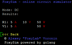
The browser can be any, even text - for example, the simulation in Lynx :
The circuit of the calculated circuit is described by a list of connections ( netlist ) consisting of directives, component descriptions and comments:
I made the description format in the spirit of SPICE with additions aimed specifically at use in teaching theoretical electrical engineering (measuring instruments, complex values etc).
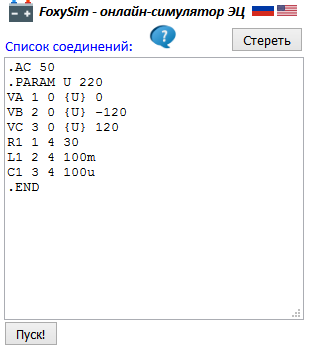
Enter a list of connections in the text field, for example, this one ( most of the lines have a fairly simple structure - for elements: name, initial node, end node, nominal; for ammeters and voltmeters: name, winding start node, winding end node, with wattmeter a little more complicated - he has two integral windings :-); You can also notice the value of the EMF, given as a parameter - not to repeat the same number three times )
press the "Start!" button and get the result :-)

The entered description of the scheme is saved in cookies , you can switch the interface language.
The simulator is implemented on Go (I am delighted with this language) as a Web application without further ado .
For modeling electrical circuits, I used the MNA method.
The simulator is available at http://foxylab.com:7777
The project code is uploaded to GitHub .
Here are some examples:
DC
circuit simulation Circuit :
Connection list:
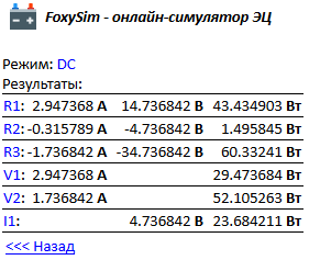
Result:
simulation of a linear sinusoidal current
circuit. Scheme:
Connection list:
Result:

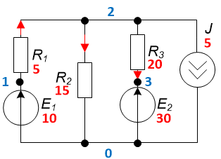
simulation of a complex asymmetric three-phase circuit with complex resistances
Scheme:
List of connections:
Result:
A brief description of the format of directives and descriptions of elements is available here (button ) A
) A
detailed description of the simulator can be found here .
A small video illustrating the process of modeling a sinusoidal current circuit -
Hidden text
Баланс электрических мощностей — штука, безусловно, хорошая, но ведь ошибиться можно и в нем. На выручку приходит моделирование. Симуляторы электрических цепей имеют богатую историю, и собрать модель цепи постоянного тока, например, в LTspice проблем не составит. Но это если в наличии у студента есть ноутбук или достаточный парк компьютеров в учебной аудитории. А так бывает не всегда и не везде :-) Есть симуляторы с графическим интерфейсом и для смартфонов, но удобство их использования — вопрос спорный. Но даже если симулятор и доступен, есть своеобразная проблема с моделированием установившегося режима цепей синусоидального тока. Если их моделировать в "transient"-режиме, то возникает вопрос с учетом длительности переходного процесса, возникающего при включении цепи — проблема "steady state detection". Но, скажете Вы, есть же режим "AC analysis". Это, конечно, так, но удобство его использования и интерпретации его результатов при решении учебной задачи расчета цепи синусоидального тока — на большого любителя. И о реактивных и полных мощностях симулятор тоже ничего не знает, да и определение показаний ваттметра — дело далеко не тривиальное.
I decided to create a minimalistic simulator of linear electric circuits of constant and sinusoidal current FoxySim with the text input of the description of the circuit, which requires using a device with a browser and the ability to enter text + Internet access.
The browser can be any, even text - for example, the simulation in Lynx :
The circuit of the calculated circuit is described by a list of connections ( netlist ) consisting of directives, component descriptions and comments:
I made the description format in the spirit of SPICE with additions aimed specifically at use in teaching theoretical electrical engineering (measuring instruments, complex values etc).
Enter a list of connections in the text field, for example, this one ( most of the lines have a fairly simple structure - for elements: name, initial node, end node, nominal; for ammeters and voltmeters: name, winding start node, winding end node, with wattmeter a little more complicated - he has two integral windings :-); You can also notice the value of the EMF, given as a parameter - not to repeat the same number three times )
.AC 50
VA 1 0 {E} 0
VB 2 0 {E} -120
VC 3 0 {E} 120
.PARAM E 220
PW1 1 4 1 3
PW2 2 5 2 3
PAA 4 6
PAB 5 7
PAC 3 8
R1 6 9 500
L1 7 9 300m
C1 8 9 50u
PVA 6 9
PVB 7 9
PVC 8 9
PVN 9 0
.END
press the "Start!" button and get the result :-)
The entered description of the scheme is saved in cookies , you can switch the interface language.
The simulator is implemented on Go (I am delighted with this language) as a Web application without further ado .
For modeling electrical circuits, I used the MNA method.
The simulator is available at http://foxylab.com:7777
The project code is uploaded to GitHub .
Here are some examples:
DC
circuit simulation Circuit :
Connection list:
.DC
V1 1 0 10
R1 1 2 5
R2 2 0 15
R3 2 3 20
V2 3 0 30
I1 2 0 5
.END
Result:
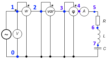
simulation of a linear sinusoidal current
circuit. Scheme:
Connection list:
.AC 50
V1 1 0 100 0
PW1 1 2 1 0
PQ1 2 3 2 0
PF1 3 4 3 0
PA1 4 5
PV1 1 0
R1 5 6 50
L1 6 7 100m
C1 7 0 80u
.END
Result:
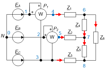
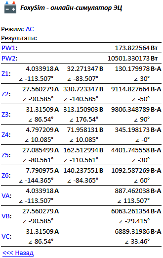
simulation of a complex asymmetric three-phase circuit with complex resistances
Scheme:
List of connections:
.AC 50
VA 1 0 {E} 0
VB 2 0 {E} -120
VC 3 0 {E} 120
.PARAM E 220
PW1 1 4 1 3
PW2 2 5 2 3
Z1 4 6 8 30
Z2 5 7 12 -50
Z3 3 8 10 90
Z4 6 7 15 0
Z5 7 8 6 -30
Z6 6 8 18 60
.END
Result:
A brief description of the format of directives and descriptions of elements is available here (button
) A detailed description of the simulator can be found here .
A small video illustrating the process of modeling a sinusoidal current circuit -