September 11, 2017 at 11:16
Fast ocean wave rendering on mobile devices
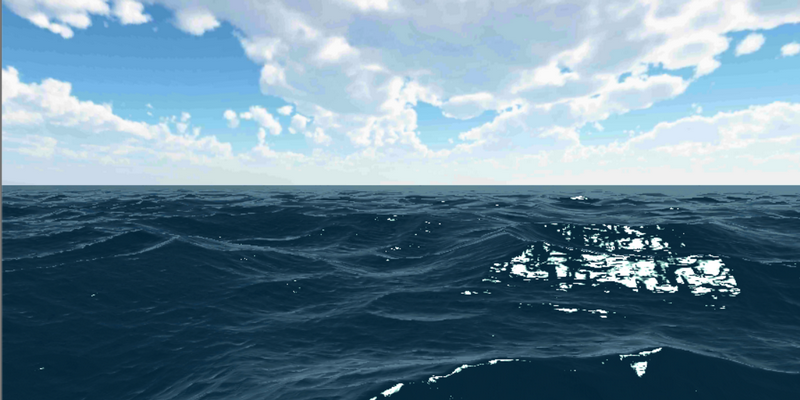
Real-time modeling of water in computer graphics remains a very difficult task. This is especially true when developing computer games in which it is necessary to create a visually attractive picture for a player within the framework of a severe limitation of computing resources. And if on desktops the programmer can still count on the presence of a powerful video card and processor, then in mobile games it is necessary to rely on much weaker hardware.
In this article, we wanted to talk about modeling waves in the open sea and present an algorithm that allowed us to achieve quite interesting results with acceptable 25-30Fps on an average Chinese phone.
In general, the experimentally selected Phillips spectrum is usually used to model the surface of waves in the open sea , i.e. decomposition of the entire spectrum of waves into Fourier components that are animated in time. However, this solution is very resource-intensive and, although fast Fourier decomposition can be performed on the video card, it is almost impossible to use it on weak smartphones both due to speed and because of the limited functionality of the video card (support for rendering in float texture, limited accuracy of calculations). An example of such a method can be found here and here .
A simpler method is to generate a wave distribution in advance (or directly in the shader), and then add the waves of different phases and amplitudes.
Despite the simplicity of the method, it can provide very impressive results, but it requires fine-tuning and has several limitations. Consider this approach in more detail and try to deal with emerging nuances in terms of image quality and speed.
Wave generation
To generate a wave, we need to know its height at a certain point. It can be obtained in many ways. For example, it’s easy to use a combination of sines, cosines from the coordinates of this point, but it is obvious that the resulting distribution of heights looks too artificial and is not suitable for solving our problem. In this case, the frequency is observed even if the direction of the waves is changed relative to each other.
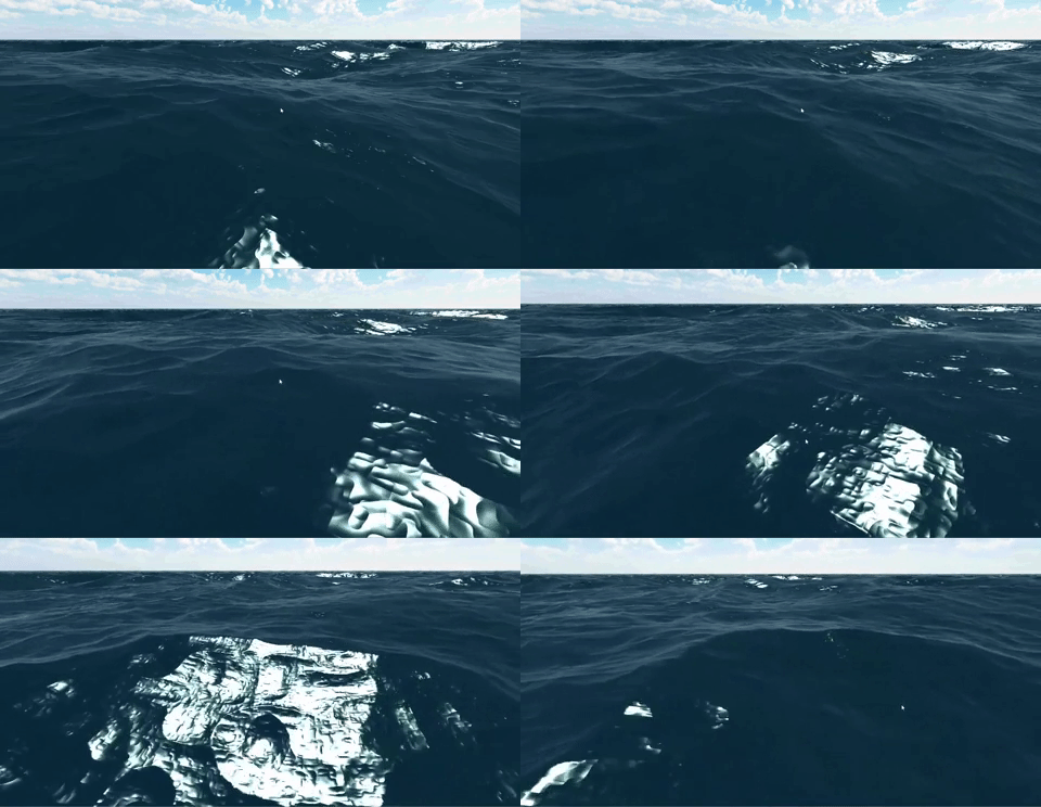
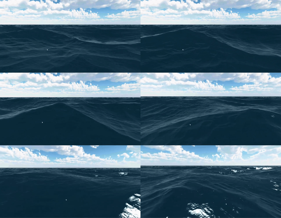
Running a little ahead, the image below shows the surface of the water obtained by adding waves of different amplitudes and heights.

The same algorithm, but from a distance there is periodicity.

It is more optimal to use Perlin noise , an example of generation of which on the shaders is presented below (the code for Cg, for GLSL requires cosmetic changes):
float rand(float2 n) {
    return frac(sin(dot(n, float2(12.9898, 4.1414))) * 43758.5453);
}
float noise(float2 n) {
    const float2 d = float2(0.0, 1.0);
    float2 b = floor(n), f = smoothstep(0, 1, frac(n));
return lerp(lerp(rand(b), rand(b + d.yx), f.x), lerp(rand(b + d.xy), rand(b + d.yy), f.x), f.y);
}
rand - Generates a pseudo-random value, and noise interpolates four random numbers in the corners of the square to any point inside it.

No frequency observed

The result is already better, the distribution of waves has changed markedly, but their shape is also different from natural waves. With a small amplitude, this is still acceptable, but for large waves, sharp peaks are characteristic.
When using the Phillips spectrum, this is solved by shifting the grid of the water surface to the peaks, which gives the necessary shape. However, a simpler method and much more effective in our case is the use of a simple formula, which leads to a satisfactory result in the form of pointed waves


The disadvantage of this method is that it leads to the appearance of circles and other closed figures visible to the eye, but with the appropriate selection of parameters this disadvantage becomes insignificant.

Phase Distribution and Animation
Obviously, the presence of only one phase (or another octave) for water is not enough to obtain realistic water and it is necessary to superimpose several waves with different amplitudes and phases, which allows to obtain both large waves and small ripples on the surface.
float amp = maxHeight / 2;
for (int i = 0; i < count; ++i){
    h += amp * phase(pos + v[i]*t);
    pos *= sp;
    amp /= sa;
}
Good results are obtained when choosing sp, sa equal to 2, but we are free to choose any values that provide acceptable results. The selection of these parameters makes it possible to obtain various types of waves and control their change up to a complete calm.
For wave animation, it is enough to shift each phase in its direction. It should be noted that the speed of movement of large waves is greater and the waves move mainly in one direction.
Optimization
As experiments have shown, it is enough to have about 7 phases to get a “tasty” picture and, in principle, there was no need for the next bike. However, the very first tests on smartphones were shocked, as FPS inexorably sought to 0, which could not but upset. Let's see how many operations in the shader will be required to display one point:
- Perlin Noise: Each vertex requires 4 random values, i.e. 4 sin, 4 fract, and other simpler operations.
- The calculation for 7 waves is 28 sin.
- Calculation of normals to the surface: In addition to the height of the point itself, we need to know the heights of 2 neighboring points. Accordingly, the number of calculations increases by 3 times - up to 84! sin calculation operations.
On the whole, one can disagree with the above reasoning, since the height of the surface as a whole is sufficient to calculate for each vertex of the mesh, which is certainly faster than counting for each point on the screen. But in this case one cannot even dream of any realism. Maxmum, that we get a very crude approximation to the desired result. Thus, all the above operations have to be calculated in the fragment shader. Optimization Options:
- Try to reduce the number of phases, but as mentioned earlier, it is desirable to have about 7 phases for an acceptable display. A smaller number significantly affects the "quality" of the waves.
- Try to replace the expensive operation of calculating noise with a sample from the finished texture. Instead of 84 sin, we already get 21 samples (since 4 sin is required for Perlin noise).
Normal Height Map
The latter option has the right to life, but fps is also too small - about 3-4 frames per second. In addition, in this case, when calculating the normal, we rest against the accuracy of storing data in the texture, which leads to the appearance of "steps" on the water. Of course, you can use a texture with real numbers, but then we will additionally limit the number of supported devices.
At the same time, to get the height of a point, we need to read the height value from the texture, but nothing prevents us from baking a normal map into this texture as well. Thus, with one sample from the texture we can get the height of the point and at the same time normal to it. Baking data into a texture can be done in advance or directly on a video card by rendering to a texture (for example, before launching an application or changing parameters).
When calculating the texture, it is necessary to ensure sufficient accuracy of the storage of normals. If you keep the normal in the usual form of the normal map, then this accuracy is insufficient, which is manifested in the artifacts of the image.
Indeed, to obtain the normal, it is enough for us to preserve only the projection of the normal in the horizontal plane (n x , n y ). In general terms, each of these components varies in the range [-1,1]. But in the case of water, the range used is significantly less, because the normals are mainly oriented upward (which is especially noticeable when generating small-amplitude waves). Thus, if we normalize this range to the maximum value, then we can significantly increase the accuracy of storing normals and, accordingly, the quality of the picture.

In this case, to generate the resulting wave, it is necessary to carefully transform the normal of each phase, taking into account the wave amplitude, its phase, as well as the scaling factor selected above.
Additional optimization
Despite the optimization, we still have a selection of 7 textures and we would like to reduce this number. As mentioned earlier, a decrease in this number in general is not desirable.
However, we store the waveform in the texture, in which we can generate several instead of one phase in advance.

This solves the problem of generating many waves with a small number of passes, however, during animation, it becomes noticeable that part of the waves moves at the same speed. To reduce this effect, you can save waves with a larger phase difference, for example 1 - 3 - 5, into the texture, and when rendering we get 1-1'-3-3'-5-5 '. We also used an approach in which the first two phases of four used one texture, and the last two are already different with a different distribution and number of phases. It is in this way that the image shown at the beginning of the post is obtained
Disadvantages of the method
- The main technical problem is that in order to obtain waves, you must be able to select from the texture in the vertex shader . This is technically supported with Opengl ES 2.0, but not all smartphones provide this functionality.
- The need for a careful selection of parameters to hide artifacts of the method and get an attractive image.
- The resulting sea is periodic in nature and this limits the scope. When flying high above the surface, the frequency is striking.
A little more about optimization
In addition to the methods described above, we tested several other optimization options. The most interesting of them seemed to us the interpolation of waves in time.
The meaning of this method is that we can render the resulting map of heights and normals into the texture at some points in time, and for others we can interpolate the heights and normals.
Thus, once every N frames, a complete surface calculation is required, and an N-1 frame can be read by a simple selection of two textures.
In this case, it turns out that one wave decreases and the next appears next. As N decreases, the animation becomes smoother, although the effectiveness of the method decreases.
Thus, it can be quite effectively used under certain conditions, for example, at a low wave velocity or at a relative distance from the surface, when the disadvantage of the method becomes less noticeable.
Skyline
At the moment, we have received quite viable and pretty water, but we did not discuss which mesh we will use for the surface of the water. Obviously, to display water to the horizon, we actually have to use an infinitely large mesh of points (at least stretch it to the clipping plane of the camera), while the number of points in it is very limited). Simple linear scaling does not work, because near the camera the mesh becomes too sparse, and in the vicinity of the horizon, on the contrary, is too thick.
The easiest way to solve this problem is to scale the mesh in the vertex shader depending on the distance to the camera. The disadvantage is quite obvious - it is difficult to choose the necessary parameters, and the resulting distribution of points will still be uneven.
Another option is to use a mesh with different details depending on the distance. But this can lead to jerks when changing the level of detail, and also requires the introduction of additional logic to control these levels.
Projected mesh
The most convenient is the use of the projected Grid method , which in general can be described as follows:
- A uniform flat grid is created, in coordinates [-1..1], always located in the camera space
- In the vertex shader, this grid is projected onto the horizontal plane.
- For the obtained point, all calculations are performed to display the water
As an analogy, you can imagine a dotted slide attached to a spotlight (camera). Where the shadow of the point falls on the plane and the desired point is located. At the same time, from the point of the camera’s location, the observer will see the same uniform grid
This method has several advantages:
- The resulting grid is uniform and easily allows you to change your size
- Not a costly method. For the correct calculation, one operation of multiplying and adding vectors in the vertex shader is enough
Lighting calculation
The basis for obtaining the correct image is the correct accounting of all components of the light flux - reflected light, light scattered in the water column, glare from the sun, etc.
In general, this is a non-trivial task, but in our case we used a simpler approach, because there was no need to display the bottom surface, caustics and others.
A detailed description of the calculation of lighting will not be, because There are many detailed articles devoted to this topic (for example, here , here ). I would only like to note the need to choose the “correct” formula for calculating the Fresnel coefficient.
In the first version of the shader, we could not achieve realistic looking water. The result was more like painted or plastic water. It turned out that we used the most primitive version to calculate the Fresnel coefficient:

. At the same time, replacing the formula with

significantly improved the realism of water. Other approximations for the Fresnel coefficient can be found here .
results
The above method of water simulation we implemented in Unity3D. To calculate the lighting and create the waveform, we used explicit vertex and fragment shaders (it could be implemented on surface shaders, but this does not play a fundamental role). When testing on Android smartphones, we got from 25 fps (Adreno 405 + MediaTek MT6735P) to 45 (Adreno 505 + Snapdragon 430). On the part of smartphones, as expected, the application did not work due to the lack of support for reading from the texture in the vertex shader . It is interesting to note that the calculation of lighting as a result turned out to be comparable with the complexity of wave generation. If necessary, you can raise fps by using other lighting models or by disabling some elements like an environment map, glare, etc.