Engineering systems of our data centers and their monitoring, part one
Hello, Habr! I’m an engineer at Miran, a company that leases various servers, hosts client equipment in its data centers, and other similar matters.

For a long time I was persuaded to write a review article about our engineering infrastructure and how we monitor it. The article long and stubbornly did not want to be born, but nevertheless was born. Congratulate me on your initiative!
Caution, a lot of pictures!
1. Introduction to data center
2. TP, ASU, PDU
3. Take a cool dip ©
4. From the terminal clamp to the PLC
What is a data center? We say "data center" - imagine the endless hangars filled with countless rows of racks with measuredly buzzing glands. The glands mysteriously wink with colorful lights from the twilight. On the front side they are blown by a cool breeze from industrial air conditioners. In cold zones, you can clearly slip through your neck and catch a cold. Therefore, admins always wear sweaters.
Our company has built two separate data centers, artlessly referred to as “Miran-1” and “Miran-2”. The first is a very familiar type, with one large engine room and several smaller floors above. The second data center is a hangar in which two mobile small data centers are currently installed, and a third is also being built. Mobile data centers - duplex structure containers, the first floor which is the server room with racks and air conditioners, it is still referred to as the server unit is mounted on the second ASU , UPS installed, and various control boards.
It so happened historically that Miran-1 did not have a single monitoring of the engineering infrastructure (sprinkle ashes on its head) and we strive to correct this shortcoming. Therefore, we will mostly talk about the second data center.
All pictures are taken from our monitoring system!
PS: photos of shields and their insides are also ours!
Miran-2 implements a guaranteed power supply system (SGE). As can be seen from the diagram below, under normal conditions, the data center is powered by two independent external inputs from the TP ; in case of power failure at the external inputs (and this sometimes happens with us) - the power comes from the diesel generator set DGU2, in fact; under the future reserve there is a place for two more.

General mimic of the input power supply "Miran-2"
Let's move on. ASU is made two-section with a sectional switch under control of ABP1. The ABP controller will close the sectioner in the event of a power failure on one or both inputs, in the latter case, after 15 seconds, a signal will be given to start the diesel generator. “Module-1 and“ Module-2 "are experiencing all these troubles on their internal UPSs.
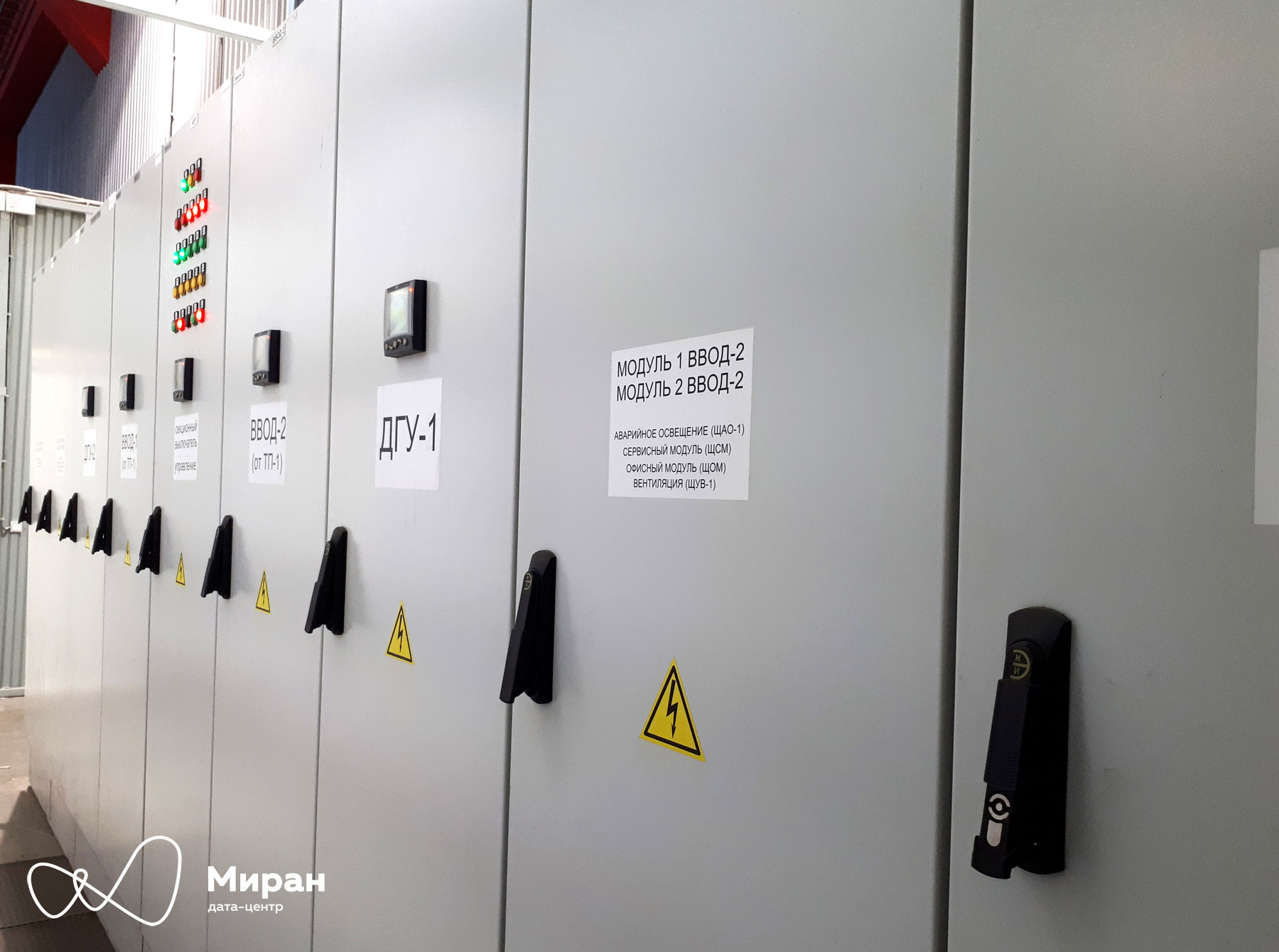
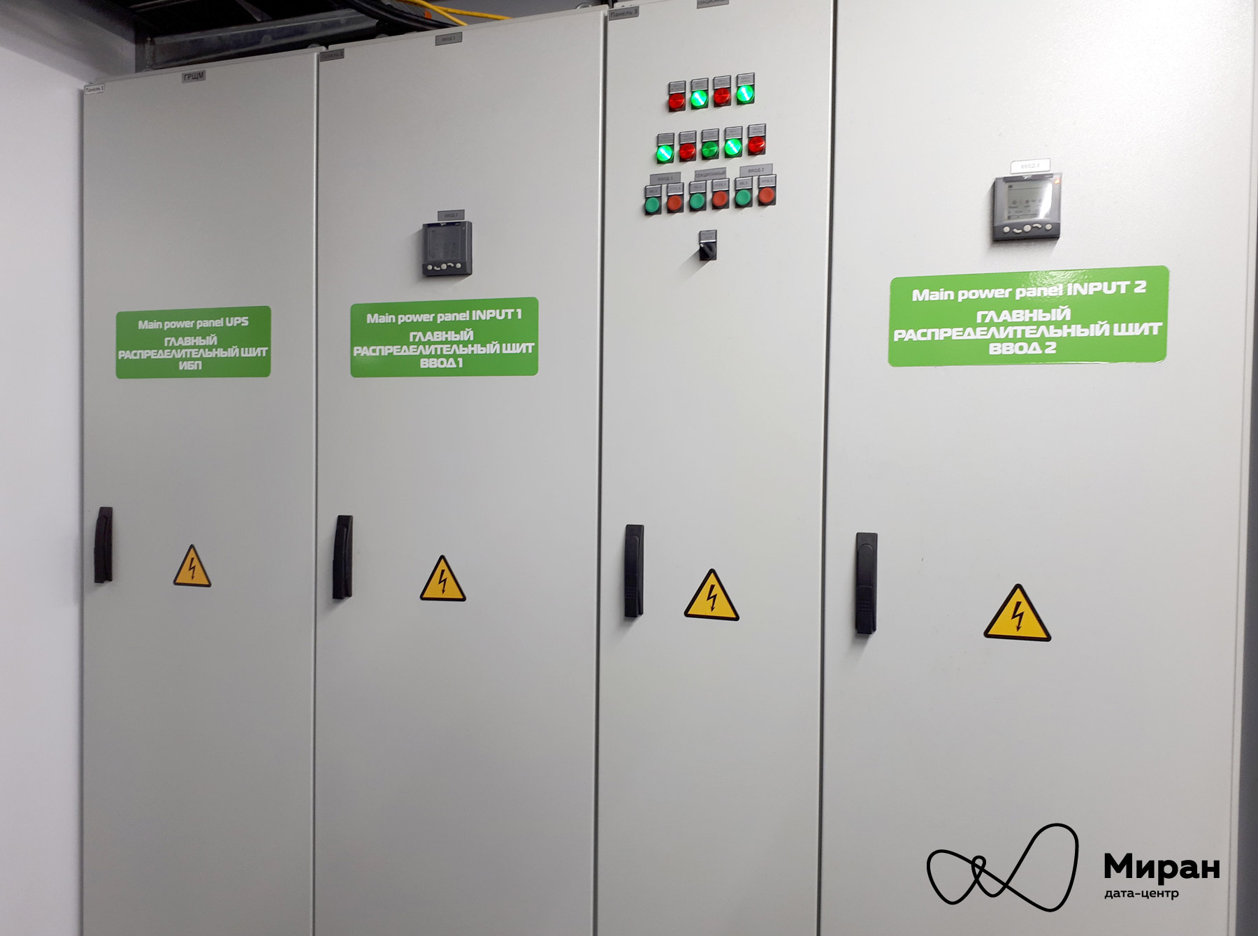
Photo of the Verkhovna Rada Miran-2. Clickable
The main purpose of the sections and their automatic machines, in addition to supplying various auxiliary lighting panels, controlling ventilation and other things, is to play the role of power inputs for “Module-1” and “Module-2” (QF1.1-.2 and QF2.1-.2 on the diagram, respectively). Each modular data center has inside its own ASU.

Mimic diagram of the main distribution board "Module-2" Photo of the main distribution board "Module-2". Clickable Mnemonic diagram of the Unit-1 power unit Mnemonic diagram of the Module-1 racks Most of the racks in Module-1 and Module-2 are from Rittal and RiT. From PDU we use: in "Module-1" - a hodgepodge from Eurolan, APC, DELTA. “Module-2” - entirely on RiT PDUs.


All client hardware, as well as engineering infrastructure, generate a lot of heat during their work. This heat must be removed, otherwise the iron will die quickly. Six inverter freon air conditioners from Daikin are engaged in the tap. All their activities are proudly called the "Freon mode", which provides a drytropical cool climate from +15 to +23 ° C in a cold corridor. This cooling system is used in both Modula-1 and Modula-2.
Also in “Module-1” there is another cooling mode, “freecooling mode”. It should be provided by four air-handling units and a dozen hoods. In theory. Unfortunately, in practice, heat removal in this way was not very effective if a little more than half of the racks were used inside. Therefore, this mode is not used for the first modular data center, remaining essentially a backup.

Mimic diagram of the server module "Module-1"

Mimic diagram of the server block "Module-2". No tributaries, onlyhardcore! freon!
Three PLCs are engaged in the polling and aggregation of information from all the periphery of the Miran-2 data center : one each for the Module and one common. These munitions are named after the notorious WAGO company.
Consider the structure of the survey system based on the solution for "Module-2".
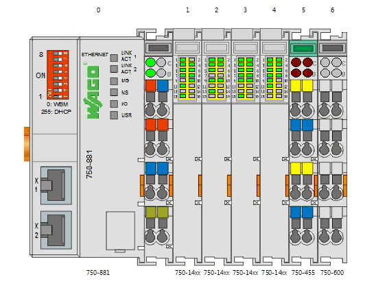
PLC bus diagram with modules, screenshot from WAGO-IO-Check Photo of the dispatching board “Module-2”. Clickable As you can see from the diagram, the PLC of the 750-881 series itself is installed on the bus , four discrete modules 750-1405 for 16 channels each and one analog module 750-455 for four channels. Through discrete modules, the PLC receives data on the state of the power supply circuit breakers (“dry” auxiliary contacts) in both sections of the main switchboard , on the state of the machines in their own switchboard , and also on the state of ventilation of the power unit. By means of an analog module - receives data from two temperature and humidity sensors (4-20 mA) here, inside the power unit. The PLC is also equipped with two Ethernet ports and through them it communicates via
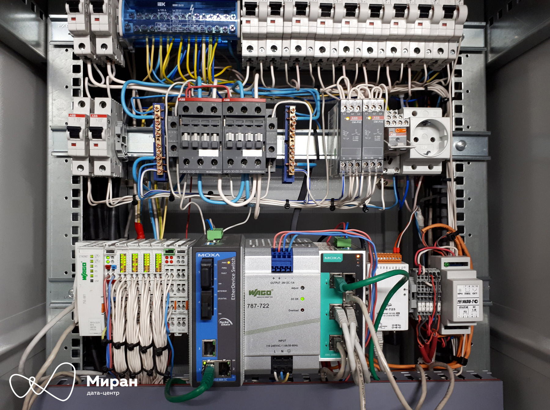
Modbus TCP / IP with a few more pieces of iron, such as:
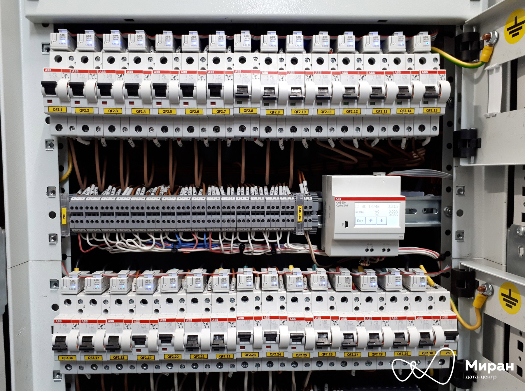
Photo ABB CMS-600 and current transformers. Clickable Photo ARIES ME110-220.3M. Clickable Photo PLC CAREL. Clickable Photo of the shield of low-current systems "Module-2". Clickable
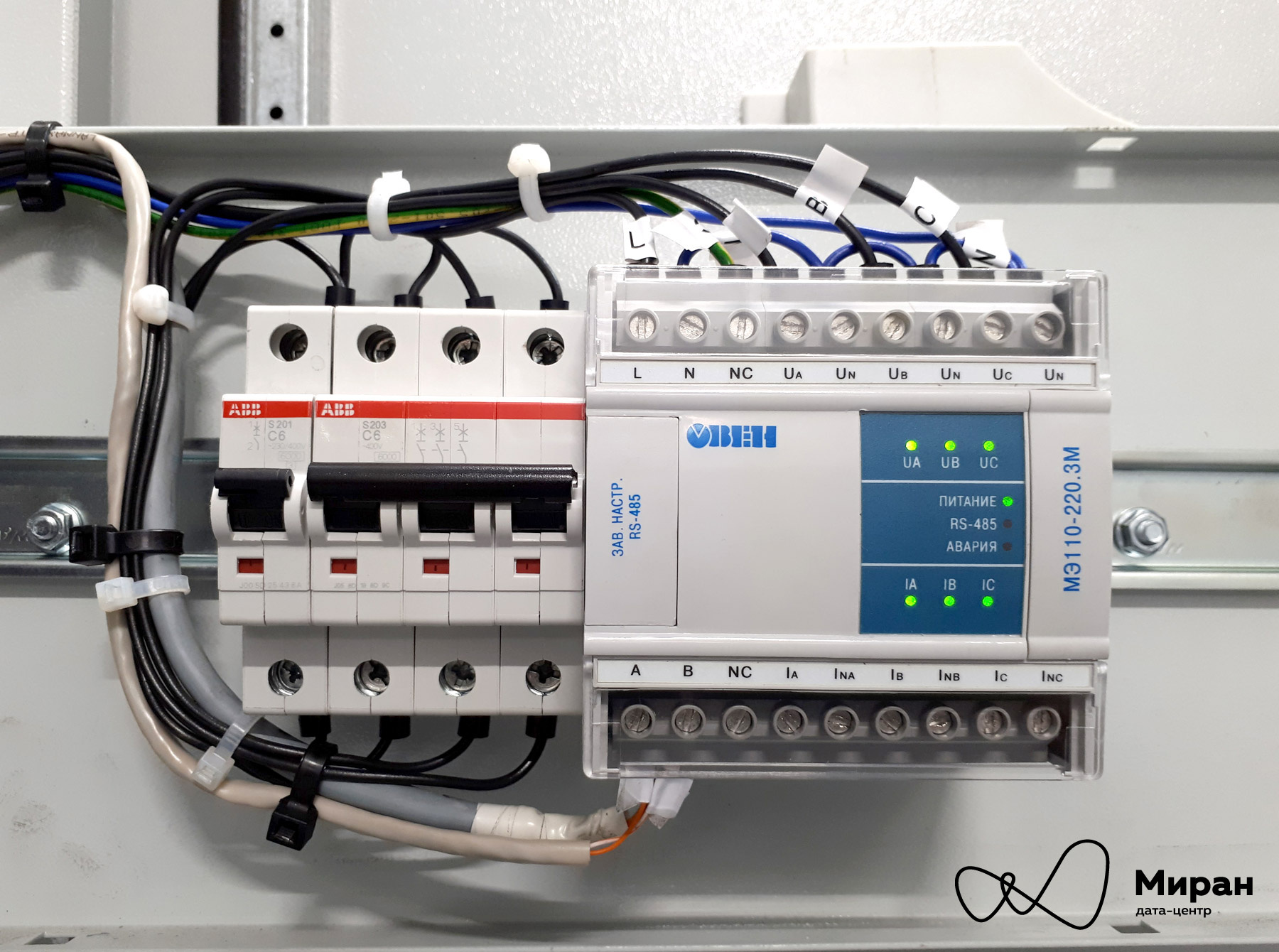

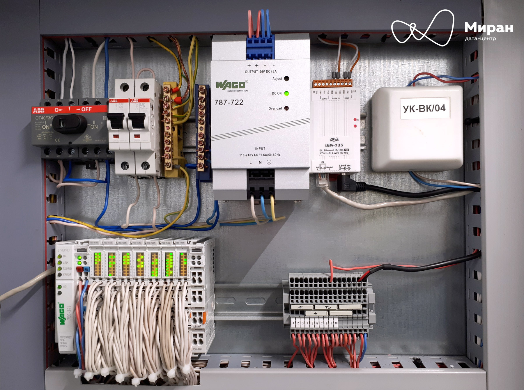
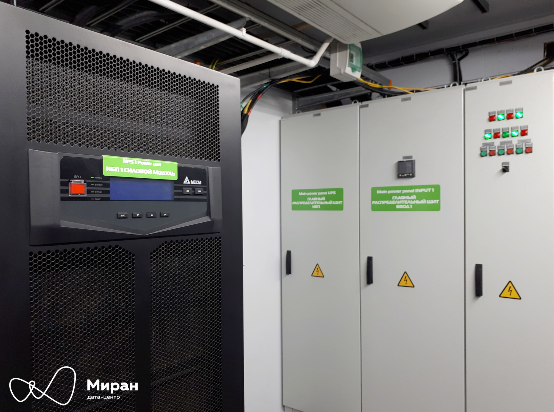
Photo UPS "Module-2". Clickable.
All information received through the program is formed into its own list of Modbus registers, which is already being polled by SCADA .
The second figure, softvarnaya
For a long time I was persuaded to write a review article about our engineering infrastructure and how we monitor it. The article long and stubbornly did not want to be born, but nevertheless was born. Congratulate me on your initiative!
Caution, a lot of pictures!
1. Introduction to data center
2. TP, ASU, PDU
3. Take a cool dip ©
4. From the terminal clamp to the PLC
Introduction to Data Center
What is a data center? We say "data center" - imagine the endless hangars filled with countless rows of racks with measuredly buzzing glands. The glands mysteriously wink with colorful lights from the twilight. On the front side they are blown by a cool breeze from industrial air conditioners. In cold zones, you can clearly slip through your neck and catch a cold. Therefore, admins always wear sweaters.
Our company has built two separate data centers, artlessly referred to as “Miran-1” and “Miran-2”. The first is a very familiar type, with one large engine room and several smaller floors above. The second data center is a hangar in which two mobile small data centers are currently installed, and a third is also being built. Mobile data centers - duplex structure containers, the first floor which is the server room with racks and air conditioners, it is still referred to as the server unit is mounted on the second ASU , UPS installed, and various control boards.
It so happened historically that Miran-1 did not have a single monitoring of the engineering infrastructure (sprinkle ashes on its head) and we strive to correct this shortcoming. Therefore, we will mostly talk about the second data center.
All pictures are taken from our monitoring system!
PS: photos of shields and their insides are also ours!
TP, ASU, PDU
Miran-2 implements a guaranteed power supply system (SGE). As can be seen from the diagram below, under normal conditions, the data center is powered by two independent external inputs from the TP ; in case of power failure at the external inputs (and this sometimes happens with us) - the power comes from the diesel generator set DGU2, in fact; under the future reserve there is a place for two more.
General mimic of the input power supply "Miran-2"
Let's move on. ASU is made two-section with a sectional switch under control of ABP1. The ABP controller will close the sectioner in the event of a power failure on one or both inputs, in the latter case, after 15 seconds, a signal will be given to start the diesel generator. “Module-1 and“ Module-2 "are experiencing all these troubles on their internal UPSs.
Photo of the Verkhovna Rada Miran-2. Clickable
The main purpose of the sections and their automatic machines, in addition to supplying various auxiliary lighting panels, controlling ventilation and other things, is to play the role of power inputs for “Module-1” and “Module-2” (QF1.1-.2 and QF2.1-.2 on the diagram, respectively). Each modular data center has inside its own ASU.
Mimic diagram of the main distribution board "Module-2" Photo of the main distribution board "Module-2". Clickable Mnemonic diagram of the Unit-1 power unit Mnemonic diagram of the Module-1 racks Most of the racks in Module-1 and Module-2 are from Rittal and RiT. From PDU we use: in "Module-1" - a hodgepodge from Eurolan, APC, DELTA. “Module-2” - entirely on RiT PDUs.
Take a cool dip ©
All client hardware, as well as engineering infrastructure, generate a lot of heat during their work. This heat must be removed, otherwise the iron will die quickly. Six inverter freon air conditioners from Daikin are engaged in the tap. All their activities are proudly called the "Freon mode", which provides a dry
Also in “Module-1” there is another cooling mode, “freecooling mode”. It should be provided by four air-handling units and a dozen hoods. In theory. Unfortunately, in practice, heat removal in this way was not very effective if a little more than half of the racks were used inside. Therefore, this mode is not used for the first modular data center, remaining essentially a backup.
Mimic diagram of the server module "Module-1"
Mimic diagram of the server block "Module-2". No tributaries, only
From terminal clamp to PLC
Three PLCs are engaged in the polling and aggregation of information from all the periphery of the Miran-2 data center : one each for the Module and one common. These munitions are named after the notorious WAGO company.
Consider the structure of the survey system based on the solution for "Module-2".
PLC bus diagram with modules, screenshot from WAGO-IO-Check Photo of the dispatching board “Module-2”. Clickable As you can see from the diagram, the PLC of the 750-881 series itself is installed on the bus , four discrete modules 750-1405 for 16 channels each and one analog module 750-455 for four channels. Through discrete modules, the PLC receives data on the state of the power supply circuit breakers (“dry” auxiliary contacts) in both sections of the main switchboard , on the state of the machines in their own switchboard , and also on the state of ventilation of the power unit. By means of an analog module - receives data from two temperature and humidity sensors (4-20 mA) here, inside the power unit. The PLC is also equipped with two Ethernet ports and through them it communicates via
Modbus TCP / IP with a few more pieces of iron, such as:
- two introductory machines of Schneider Electric company, from them information on input capacities, voltages, currents and other information is obtained;
- two systems for measuring currents of the ABB company in tandem with two input modules from the company Aries - the result of their joint work is the calculation of rack-mount power;
- CAREL controllers and 6 of their wards - Daikin air conditioners;
- and, finally, a younger brother - a kapler 750-342 with seven discrete modules. Their task is to monitor the status of 48 switches + 12 redundant in the server block with 24 racks.
Photo ABB CMS-600 and current transformers. Clickable Photo ARIES ME110-220.3M. Clickable Photo PLC CAREL. Clickable Photo of the shield of low-current systems "Module-2". Clickable
Separately, it is worth mentioning the UPS, they are interrogated directly by SCADA, bypassing the PLC, using the SNMP protocol.
Photo UPS "Module-2". Clickable.
All information received through the program is formed into its own list of Modbus registers, which is already being polled by SCADA .
A small piece from the main program
(* PLC_A2 *)
%QX256.0 := A2_1QF1;	//присваиваем каждому биту 256го слова
%QX256.1 := A2_1QF2;	//текущее состояние различных автоматов
%QX256.2 := A2_QS1;
%QX256.3 := A2_QS2;
%QX256.4 := A2_3QF1;
%QX256.5 := A2_3QF2;
%QX256.6 := A2_3QF3;
%QX256.7 := A2_3QF4;
%QX256.8 := A2_3QF5;
%QX256.9 := A2_3QF6;
%QX256.10 := A2_3QF7;
%QX256.11 := A2_3QF8;
%QX256.12 := A2_3QF9;
%QX256.13 := A2_3QF10;
%QX256.14 := A2_KM1;
%QX256.15 := A2_KM2;
(* QF1 *)   //вводной автоматический выключатель № 1
%QW332 := QF1_I_L1;    //токи по фазам
%QW333 := QF1_I_L2;
%QW334 := QF1_I_L3;
%QW335 := QF1_U_L12;   //линейные (межфазные) напряжения
%QW336 := QF1_U_L23;
%QW337 := QF1_U_L31;
%QW338 := QF1_U_L1;   //фазные (фаза-нуль) напряжения
%QW339 := QF1_U_L2;
%QW340 := QF1_U_L3;
%QW341 := QF1_P_L1;   //активная мощность по фазам
%QW342 := QF1_P_L2;
%QW343 := QF1_P_L3;
%QW344 := QF1_P_Sum;  //суммарная активная мощность (кВт)
%QW345 := QF1_Q_L1;   //реактивная мощность по фазам
%QW346 := QF1_Q_L2;
%QW347 := QF1_Q_L3;
%QW348 := QF1_Q_Sum;  //суммарная реактивная мощность (квар)
%QW349 := QF1_S_Sum;  //полная мощность (кВА)
%QW350 := QF1_CosF;   //коэффициент мощности
Another slice from another routine
//Это работа кодогенератора CODESYS, в котором есть удобный настройщик связи
//с периферией по Modbus TCP/IP. Эта подпрограмма, в частности, отвечает
//за получение от ОВЕН МЭ110-220.3М показаний
//по трем напряжениям фаза-нейтраль
PROGRAM MBCFG_subCMS_1(* generated by config one prg for each slave *)
VAR_OUTPUT
U_L1  :  WORD; (**)
U_L2  :  WORD; (**)
U_L3  :  WORD; (**)
/*--- system variables (read only) ----------------------------------------*/
MBCFG_IpAddress    :   STRING(12) := 'XXX.XXX.XXX.XXX';//IP-адрес Slave-устройства
MBCFG_Port         :   UINT := 502;               //Порт, дефолтный
MBCFG_UnitID       :   BYTE := 2;                 //ID Slave-устройства
MBCFG_TimeOut      :   TIME := t#300ms;           //Таймаут на получение ответа
MBCFG_RequestDelay :   TIME := t#1000ms;          //Задержка до следующего опроса
MBCFG_Error        :   MBCFG_eERROR := MBCFG_START_UP;
MBCFG_LastJob      :   MBCFG_typCOM_JOB;
/*-------------------------------------------------------------------------*/
END_VAR
VAR CONSTANT
    zz_VARIABLECOUNT:   INT := 3; (* number of variables  *)
    zz_JOBCOUNT     :   INT := 1; (* number of jobs *)
END_VAR
VAR
/*=== VARIABLE LIST =============*/
zz_VariableList :   ARRAY[1..zz_VARIABLECOUNT] OF MBCFG_typVARIABLE :=
    ( DataType        := MBCFG_TYPE_WORD,
      ByteOrder       := MBCFG_BYTE_ORDER_0,
      BitSize         := 16,
      ptVar           := 0,
      ReadJobIndex    := 1,
      ReadStartBitNo  := 0,
      WriteJobIndex   := 0,
      WriteStartBitNo := 0 ),
   (  DataType        := MBCFG_TYPE_WORD,
      ByteOrder       := MBCFG_BYTE_ORDER_0,
      BitSize         := 16,
      ptVar           := 0,
      ReadJobIndex    := 1,
      ReadStartBitNo  := 32,
      WriteJobIndex   := 0,
      WriteStartBitNo := 0 ),
   (  DataType        := MBCFG_TYPE_WORD,
      ByteOrder       := MBCFG_BYTE_ORDER_0,
      BitSize         := 16,
      ptVar           := 0,
      ReadJobIndex    := 1,
      ReadStartBitNo  := 64,
      WriteJobIndex   := 0,
      WriteStartBitNo := 0
   );
/*=== JOB LIST ==================*/
zz_JobList     :   ARRAY[1..zz_JOBCOUNT] OF MBCFG_typCOM_JOB :=
   (  Functioncode            := 3, //Номер функции, 0x03, Read Holding Registers
      ReadStartAddress        := 26,//Адрес первого регистра
      ReadQuantity            := 5, //Кол-во регистров, которые следует прочесть
      WriteStartAddress       := 0,
      WriteQuantity           := 0,
      ptReadData              := 0,
      ptWriteData             := 0
   );
zz_DataField_1_Read       :       ARRAY[1..5] OF WORD;
/*=== MODBUS MASTER ==============*/
zz_MBCFG_MASTER_ETH :       MBCFG_MASTER_TCP;
END_VAR
/*--- for each variable -------------------------*/
   zz_VariableList[1].ptVar := ADR(U_L1);
   zz_VariableList[2].ptVar := ADR(U_L2);
   zz_VariableList[3].ptVar := ADR(U_L3);
/*-----------------------------------------------*/
/*--- for each job -----------------------------------*/
zz_JobList[1].ptReadData   := ADR(zz_DataField_1_Read);
/*----------------------------------------------------*/
/*#### START OF FIXED CODE #####################################*/
zz_MBCFG_MASTER_ETH(	strIpAddress    := MBCFG_IpAddress,
                        uiPort          := MBCFG_Port,
                        bUnitID         := MBCFG_UnitID,
                        tTimeOut        := MBCFG_TimeOut,
                        iVariableCount  := zz_VARIABLECOUNT,
                        ptVariableList  := ADR(zz_VariableList),
                        iJobCount       := zz_JOBCOUNT,
                        ptJobList       := ADR(zz_JobList),
                        tRequestDelay   := MBCFG_RequestDelay,
                        eError          => MBCFG_Error,
                        LastJob         => MBCFG_LastJob
                    );
%QW377 := U_L1;
%QW378 := U_L2;
%QW379 := U_L3;
The second figure, softvarnaya