LDraw + Unity. How I generated Lego
Happy New Year! My name is Grisha, and I am the founder of CGDevs. The holidays are just around the corner, someone has already dressed up a Christmas tree, has eaten tangerines and is fully charged with the New Year mood. But today it is not about this. Today we will talk about a wonderful format called LDraw and about a plug-in for Unity, which I implemented and uploaded to OpenSource. Link to the project and source code to the article, as always, attached. If you are the same as I love lego - welcome under cat.

LDraw format
Let's start with what is LDraw? LDraw is an open standard for LEGO CAD programs that allows users to create LEGO models and scenes. In general, there are various programs and plugins that can be used to visualize LDraw (for example, there is a plugin for Blender).
The format itself is well documented, and we will talk about its latest version, or rather, about 1.0.2.
LDraw is a text format whose files must be created in UTF-8 encoding. Files supported by the format must have the extension ldr, dat or mdp. Each line of the file is a separate command responsible for a particular function.
An important detail of the format is the right-handed coordinate system (Y pointing up) - we will discuss it in more detail later in the context of the unit, and also that the format is recursive (most of the files contain references to other files).
LDraw Commands
In general, this information can be found in the official documentation , but let's look at a little in the context of Unity. The total LDraw format supports 6 types of commands.
0. A comment or a meta command are special commands that we will barely touch in the plugin. Example:
1. File reference . In fact, the most difficult in the integration and interesting team. It looks like -
2. Line - not used in the case of Unity, you need to highlight the faces with a certain color in CAD systems.
3.4. Triangle and square . The commands are quite simple, but there is one important nuance, since the LDraw format is not designed for 3D modeling, the detour of triangles and squares in it is not standardized. This is important because depending on the circumference of a triangle, a unit determines the direction of the calculated normal, and which side of the triangle is the back and which is the front (which is also important for drawing and culling)
Example commands:
Triangle -
Square -
5. Optional line - also not used.
Colors in LDraw
As you can see in most of the commands responsible for drawing, the color goes right after the type of command. The colors are well documented in these two articles at www.ldraw.org/article/299.html and www.ldraw.org/article/547.html , but let 's talk about the features that I encountered during implementation. There is a little more to talk about the formats and the so-called “Scope” format. The format contains 3 types of files.
DAT is essentially the basic elements of which parts are already being assembled, or some basic details. If you do not render individual parts - the color specified in them is not important. Most often there are standard colors of the official standard.
LDR- this is the most interesting, in terms of colors, and where Scope plays a role. The rule is quite simple, although the site describes complex languages. If you refer from one ldr to another, ignore the color specified in the root.
For example, part of the file 30051-1 - X-wing Fighter - Mini.mpd (X-wing in the picture above):
In all dat files we take into account the specified color, and in the team 1 72 0 -8 -70 1 0 0 0 1 0 0 0 1 30051 - Nose.ldr - ignore 72, and use the values from the file 30051 - Nose.ldr .
MDP is a model file, most often contains a description of several ldr files. From the point of view of color is also not particularly important. The only thing that we consider when parsing is the FILE meta command .
Models in LDraw
The most beautiful thing in the LDraw format is that it has quite a lot of Lego fans. Many interesting kits can be found on the official website omr.ldraw.org , but, in addition to this, many can be found in separate forums.
We talked about the format, now it's time to talk a little about the plugin for Unity.
Plugin for Unity
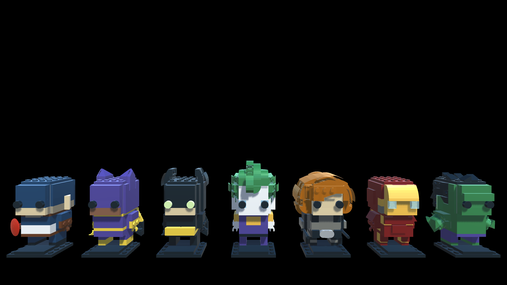
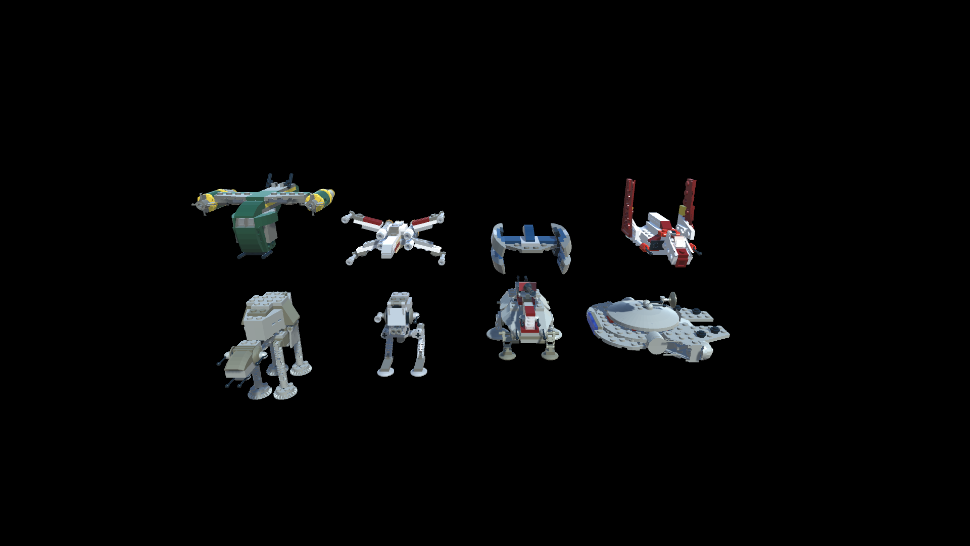
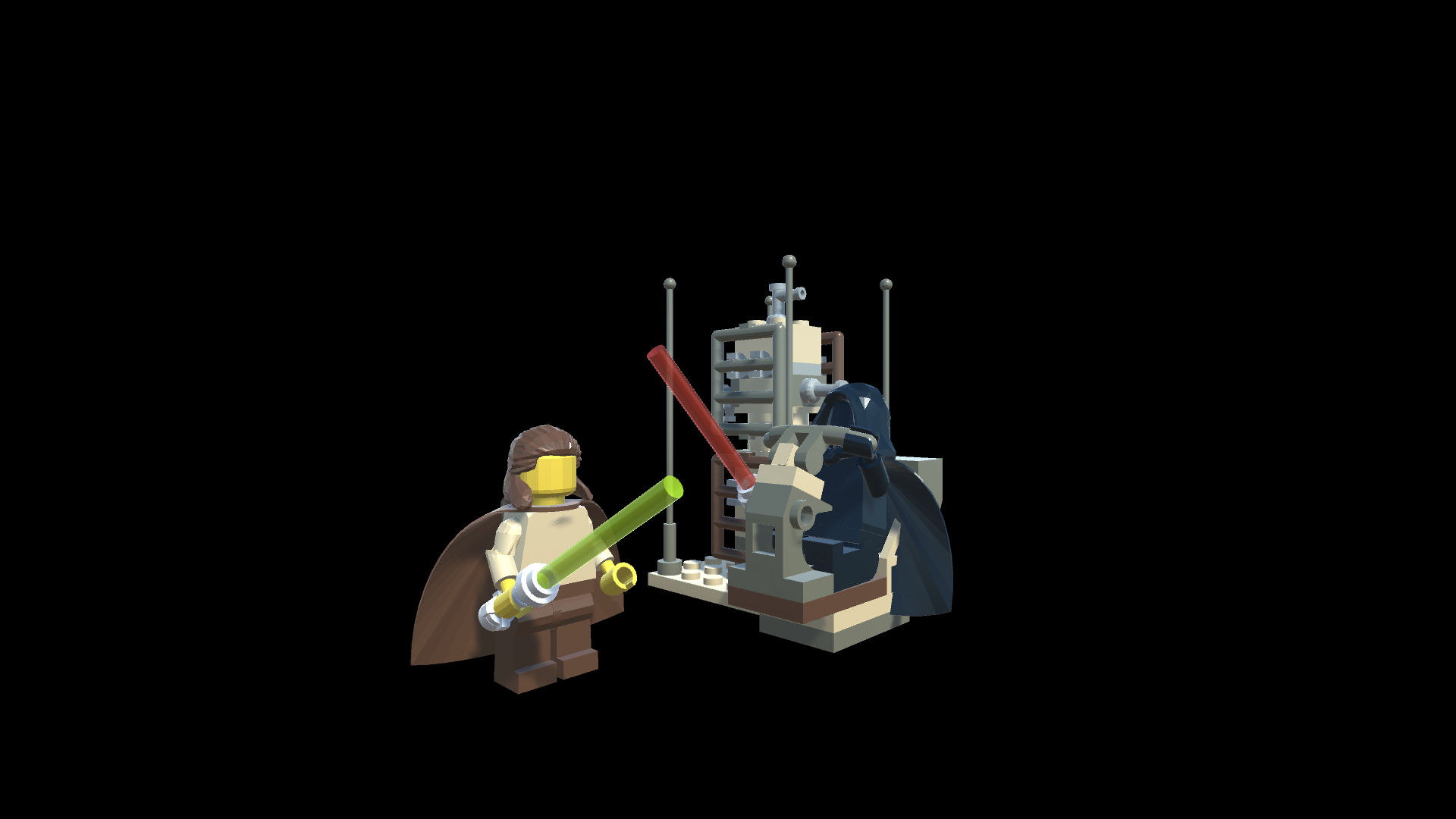
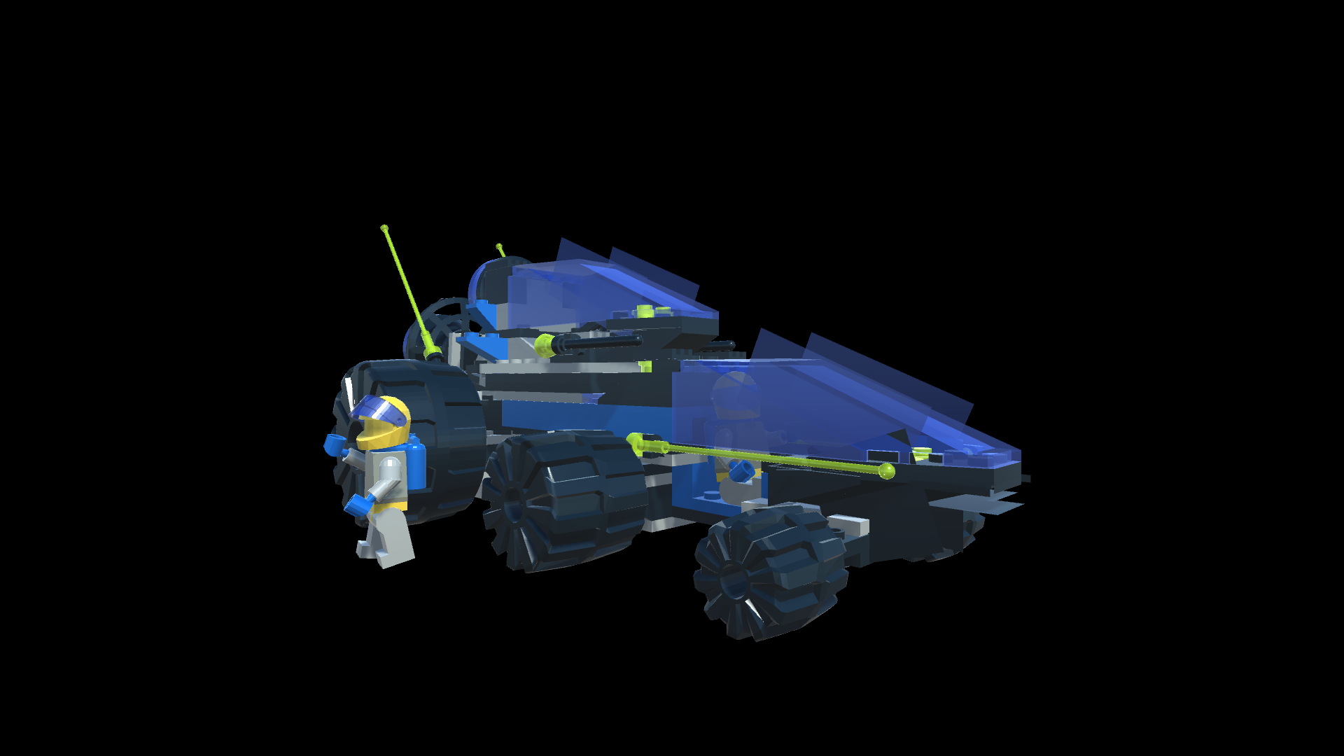
Plugin provides the ability to generate 3D models based on LDraw files. You can see the results in the pictures from the article. Important: if you have a weak device, it is better to open only mini scenes in the Demo folder. Models are not optimized and always generate backface.
Now let's talk a little about implementation. Currently, most of the above is supported.
One of, perhaps, the most important features are different coordinate systems. The problem is that in the format of the right-sided coordinate system, and in Unity - left-sided. What this basically means is that all the turns and the TRS matrix will not work correctly. Negative Y is easy to beat - we reflect all coordinates relative to Vector3.up and we get the necessary ones (multiply by -1). But in the case of the TRS matrix all the more difficult. Since the format is recursive, it is impossible to simply reflect the matrix, since Matrix.Identity everywhere will turn into a reflection matrix and each nesting will reflect our model along the Y axis, which will lead to incorrect display (if you keep a positive scale). So far I have come to a not quite right decision in the form of what allowed the negative scale, what will need to be redone in future versions.
The second feature is the orientation of the triangles. For quads, it is realized that the triangles look in one direction:
But to uniquely determine based on the format, in which direction the triangles should be directed in principle - a non-trivial task. For this reason, both sides are now generated always.
In addition, due to the fact that the format is recursive, the hierarchical Unity system has come in handy like never before.
Using recursion in two methods, we generate the necessary meshes and apply TRS (the implementation can be found in the previous article ), and thus we get all the necessary offsets for us in a convenient format:
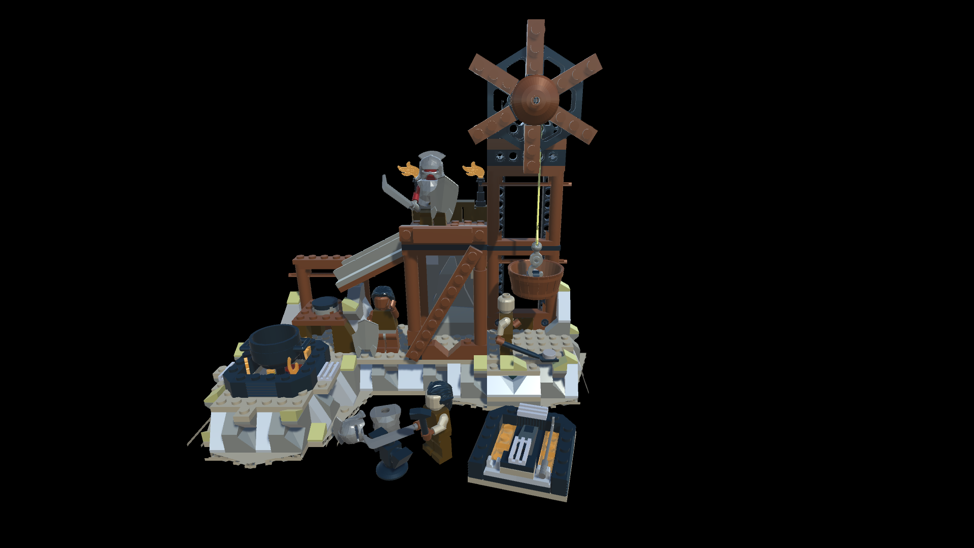
And in the end we get such beautiful visualizations:
You can see more in the repository on Github .
In general, the development of the plug-in a lot of ideas, I want to introduce such functionality as:
But at the moment, the plugin allows you to use Lego models in Unity3d, which is pretty cool. (All images for the article are made using the plugin) The entire project code is laid out under the MIT license, but I advise you to look at the license for specific models on LDraw resources.
Thank you for your attention, I hope you have learned something new for yourself, and you are interested in the format and the plugin! If there is time, I will continue to develop it and will be glad to help in this difficult task.
LDraw format
Let's start with what is LDraw? LDraw is an open standard for LEGO CAD programs that allows users to create LEGO models and scenes. In general, there are various programs and plugins that can be used to visualize LDraw (for example, there is a plugin for Blender).
The format itself is well documented, and we will talk about its latest version, or rather, about 1.0.2.
LDraw is a text format whose files must be created in UTF-8 encoding. Files supported by the format must have the extension ldr, dat or mdp. Each line of the file is a separate command responsible for a particular function.
An important detail of the format is the right-handed coordinate system (Y pointing up) - we will discuss it in more detail later in the context of the unit, and also that the format is recursive (most of the files contain references to other files).
LDraw Commands
In general, this information can be found in the official documentation , but let's look at a little in the context of Unity. The total LDraw format supports 6 types of commands.
0. A comment or a meta command are special commands that we will barely touch in the plugin. Example:
0 !META command additional parameters1. File reference . In fact, the most difficult in the integration and interesting team. It looks like -
1 colour x y z a b c d e f g h i filewhere the parameters are a TRS matrix (for more details about TRS you can readin this article ). In the context of a unit in the form/ a d g 0 \
| b e h 0 |
| c f i 0 |
\ x y z 1 /2. Line - not used in the case of Unity, you need to highlight the faces with a certain color in CAD systems.
3.4. Triangle and square . The commands are quite simple, but there is one important nuance, since the LDraw format is not designed for 3D modeling, the detour of triangles and squares in it is not standardized. This is important because depending on the circumference of a triangle, a unit determines the direction of the calculated normal, and which side of the triangle is the back and which is the front (which is also important for drawing and culling)
Example commands:
Triangle -
3 colour x1 y1 z1 x2 y2 z2 x3 y3 z3Square -
4 colour x1 y1 z1 x2 y2 z2 x3 y3 z3 x4 y4 z45. Optional line - also not used.
Colors in LDraw
As you can see in most of the commands responsible for drawing, the color goes right after the type of command. The colors are well documented in these two articles at www.ldraw.org/article/299.html and www.ldraw.org/article/547.html , but let 's talk about the features that I encountered during implementation. There is a little more to talk about the formats and the so-called “Scope” format. The format contains 3 types of files.
DAT is essentially the basic elements of which parts are already being assembled, or some basic details. If you do not render individual parts - the color specified in them is not important. Most often there are standard colors of the official standard.
LDR- this is the most interesting, in terms of colors, and where Scope plays a role. The rule is quite simple, although the site describes complex languages. If you refer from one ldr to another, ignore the color specified in the root.
For example, part of the file 30051-1 - X-wing Fighter - Mini.mpd (X-wing in the picture above):
Example
1 71 -10 0 50 0 0 1 0 1 0 -1 0 0 60470a.dat
1 71 10 0 50 0 0 -1 0 1 0 1 0 0 60470a.dat
0 STEP
1 19 0 8 50 0 0 -1 0 1 0 1 0 0 4032b.dat
0 STEP
0 ROTSTEP 35 55 0 ABS
1 19 0 -16 0 0 0 -1 0 1 0 1 0 0 3623.dat
1 72 0 -16 50 0 0 -1 0 1 0 1 0 0 3022.dat
0 STEP
1 72 0 -8 -70 1 0 0 0 1 0 0 0 1 30051 - Nose.ldr
In all dat files we take into account the specified color, and in the team 1 72 0 -8 -70 1 0 0 0 1 0 0 0 1 30051 - Nose.ldr - ignore 72, and use the values from the file 30051 - Nose.ldr .
MDP is a model file, most often contains a description of several ldr files. From the point of view of color is also not particularly important. The only thing that we consider when parsing is the FILE meta command .
Models in LDraw
The most beautiful thing in the LDraw format is that it has quite a lot of Lego fans. Many interesting kits can be found on the official website omr.ldraw.org , but, in addition to this, many can be found in separate forums.
We talked about the format, now it's time to talk a little about the plugin for Unity.
Plugin for Unity
Plugin provides the ability to generate 3D models based on LDraw files. You can see the results in the pictures from the article. Important: if you have a weak device, it is better to open only mini scenes in the Demo folder. Models are not optimized and always generate backface.
Now let's talk a little about implementation. Currently, most of the above is supported.
One of, perhaps, the most important features are different coordinate systems. The problem is that in the format of the right-sided coordinate system, and in Unity - left-sided. What this basically means is that all the turns and the TRS matrix will not work correctly. Negative Y is easy to beat - we reflect all coordinates relative to Vector3.up and we get the necessary ones (multiply by -1). But in the case of the TRS matrix all the more difficult. Since the format is recursive, it is impossible to simply reflect the matrix, since Matrix.Identity everywhere will turn into a reflection matrix and each nesting will reflect our model along the Y axis, which will lead to incorrect display (if you keep a positive scale). So far I have come to a not quite right decision in the form of what allowed the negative scale, what will need to be redone in future versions.
The second feature is the orientation of the triangles. For quads, it is realized that the triangles look in one direction:
Code preparation for squares
publicoverridevoidPrepareMeshData(List<int> triangles, List<Vector3> verts)
{
	var v = _Verts;
	var nA = Vector3.Cross(v[1] - v[0], v[2] - v[0]);
	var nB = Vector3.Cross(v[1] - v[0], v[2] - v[0]);
	var vertLen = verts.Count;
	triangles.AddRange(new[]
	{
		vertLen + 1,
		vertLen + 2,
		vertLen,
		vertLen + 1,
		vertLen + 3,
		vertLen + 2
	});
	var indexes = Vector3.Dot(nA, nB) > 0 ? newint[] {0, 1, 3, 2} : newint[] {0, 1, 2, 3};
	for (int i = 0; i < indexes.Length; i++)
	{
		verts.Add(v[indexes[i]]);
	}
}
But to uniquely determine based on the format, in which direction the triangles should be directed in principle - a non-trivial task. For this reason, both sides are now generated always.
In addition, due to the fact that the format is recursive, the hierarchical Unity system has come in handy like never before.
Using recursion in two methods, we generate the necessary meshes and apply TRS (the implementation can be found in the previous article ), and thus we get all the necessary offsets for us in a convenient format:
Methods for generating a model on stage
publicclassLDrawModel
{
public GameObject CreateMeshGameObject(Matrix4x4 trs, Material mat = null, Transform parent = null)
    {
        if (_Commands.Count == 0) returnnull;
        GameObject go = new GameObject(_Name);
        var triangles = new List<int>();
        var verts = new List<Vector3>();
        for (int i = 0; i < _Commands.Count; i++)
        {
            var sfCommand = _Commands[i] as LDrawSubFile;
            if (sfCommand == null)
            {
                _Commands[i].PrepareMeshData(triangles, verts);
            }
            else
            {
                sfCommand.GetModelGameObject(go.transform);
            }
        }
        if (mat != null)
        {
            var childMrs = go.transform.GetComponentsInChildren<MeshRenderer>();
            foreach (var meshRenderer in childMrs)
            {
                meshRenderer.material = mat;
            }
        }
        if (verts.Count > 0)
        {
            var visualGO = new GameObject("mesh");
            visualGO.transform.SetParent(go.transform);
            var mf = visualGO.AddComponent<MeshFilter>();
            mf.sharedMesh = PrepareMesh(verts, triangles);
            var mr = visualGO.AddComponent<MeshRenderer>();
            if (mat != null)
            {
                mr.sharedMaterial = mat;
            }
        }
        go.transform.ApplyLocalTRS(trs);
        go.transform.SetParent(parent);
        return go;
    }
}
publicclassLDrawSubFile : LDrawCommand
{
	publicvoidGetModelGameObject(Transform parent)
	{
		_Model.CreateMeshGameObject(_Matrix, GetMaterial(), parent);
	}
}
And in the end we get such beautiful visualizations:
You can see more in the repository on Github .
In general, the development of the plug-in a lot of ideas, I want to introduce such functionality as:
- Smoothing some shapes
- Generation only front face
- Constructor and unload models back to LDraw format
- By steeper shader for plastic with subsurface scattering (and the right set of materials in general)
- Unwrap UV for lightmaps
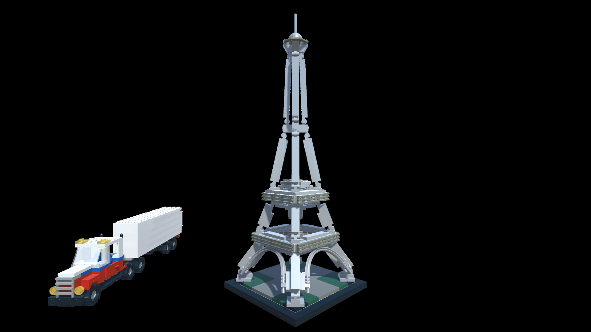
- Optimization of models (now most consist of 500k +, and for example the model of the Eiffel Tower 2.8 million polygons)
But at the moment, the plugin allows you to use Lego models in Unity3d, which is pretty cool. (All images for the article are made using the plugin) The entire project code is laid out under the MIT license, but I advise you to look at the license for specific models on LDraw resources.
Thank you for your attention, I hope you have learned something new for yourself, and you are interested in the format and the plugin! If there is time, I will continue to develop it and will be glad to help in this difficult task.