Post-effects in mobile games
Most publications on graphics for consoles and desktops talk about something new, and for mobile platforms, optimization of an existing one is always at the forefront.
As for post-processing, its magical effect on photography was discovered long before the first computers appeared, and its mathematical and algorithmic basis, created for digital image processing, successfully fit into the programmable GPU pipeline.
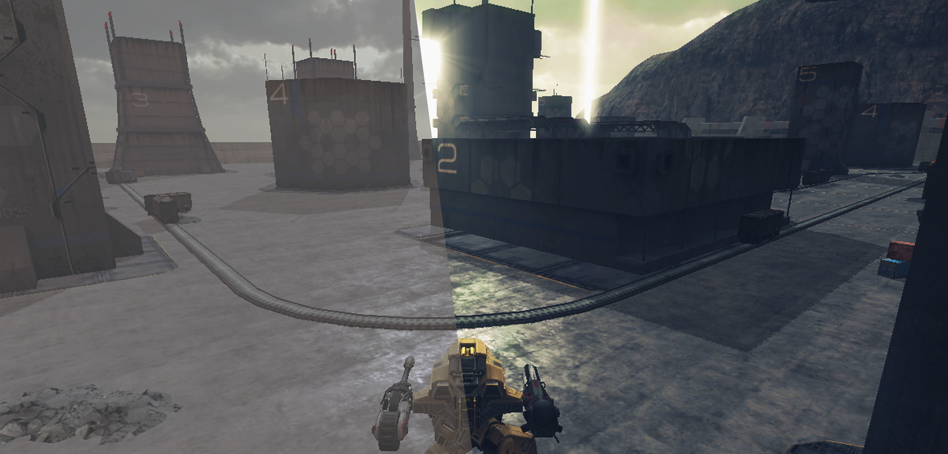
In addition to the fact that post-effects (or rather, their not very competent use) are a matter of hatred among players, they are also almost the only way to quickly and cheaply “revive” and “refresh” a picture. How high-quality this “revival” will turn out and whether it will turn out as a result of “freshness” depends for the most part on artists.
A slightly refreshing screenshot of War Robots.
As mentioned above, this article will be devoted mainly to optimization. For those who are not in the know, books from the GPU Gems series will be an excellent introductory course, the first three of which are available on the NVidia website [1].
These examples are implemented on Unity, however, the optimization methods described here are applicable to any development environment.
Optimal post-processing architecture
There are two ways to render post effects:
- sequential - when rendering is divided into separate steps and at each step only one post-effect per step is applied to the image;
- batch - first the intermediate result of each effect is rendered, and then all the post-effects are applied at the final step.
Sequential rendering is easier to implement and more convenient in terms of configuration. It is elementarily implemented as a list of objects of the “post-effect” type, the rendering order of which is arbitrary in theory (in practice, no), and moreover, the same type of effect can be applied several times. In fact, such advantages are in demand only in isolated cases.
At the same time, batch rendering is noticeably more efficient since it saves the total number of memory accesses. The latter is most relevant for mobile platforms on which increased computing load is accompanied by increased heat transfer (who would have thought). And even if the device manages to issue the required frame rate, it is unlikely that the player will be comfortable playing with a hot “brick” in their hands.
For clarity, I will give a sequential and batch scheme for rendering post effects used in War Robots.
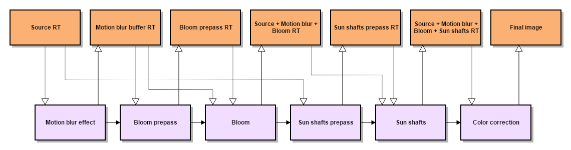
Sequential rendering: 8 reads, 6 records.
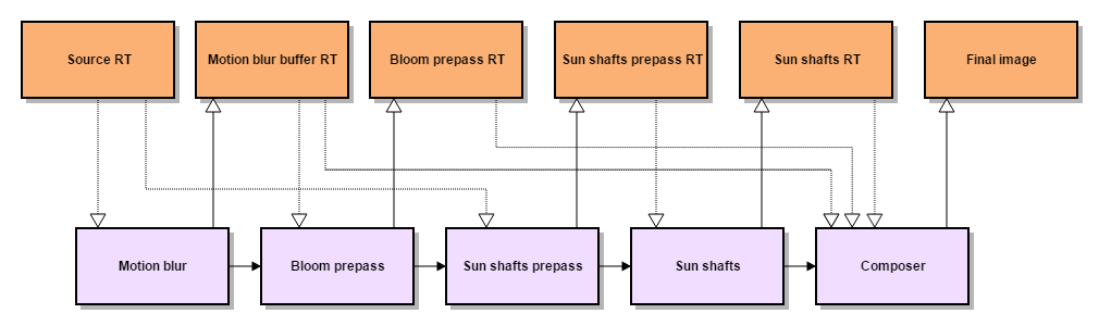
Batch rendering: 7 reads, 5 records.
Batch rendering for Unity is implemented in the Post Processing Stack module [2].
The sequence of applying post effects without changing the code cannot be changed (but it is not necessary), but you can disable individual post effects. In addition, the module heavily uses the Under’s built-in resource cache RenderTexture [3], so that the code for a particular post-effect usually contains only rendering instructions.
Resources the same post-effect requests directly during rendering, and frees them upon completion. This allows you to organize the reuse of resources in subsequent post-effects, since the cache only deletes those resources that have not been claimed in the past few frames.
The final stage in batch rendering is a compositional effect that combines the results of all the previous steps and renders them using the multivariate “uber shader”. In Unity3D, such a shader can be made using preprocessor directives #pragma multi_compile or #pragma shader_feature.
In general, we liked the Post Processing Stack, but nevertheless, it did not go without a file. We needed a scalable module with the ability to add or replace post-effects (including prepasses), as well as modify the hard-coded pipe-line, which sets the rendering sequence, and the compositional “uber shader”. In addition, the quality settings of the effect and its parameters on a specific scene were posted in the effects.
Fillrate optimization
The main rendering method in post-processing is blitting: the specified shader is applied to all fragments of the texture used as the render target. Thus, rendering performance depends on the size of the texture and the computational complexity of the shader. The simplest way to improve performance (namely, reducing the size of the texture) affects the quality of post-processing.
But if it is known in advance that rendering is necessary only in a certain area of the texture, you can optimize the process, for example, by replacing blitting with rendering of a 3D model. Of course, no one forbids using the viewport settings instead, but the 3D model differs from blitting in the increased volume of per-vertex data, which in turn allows the use of more "advanced" vertex shaders.
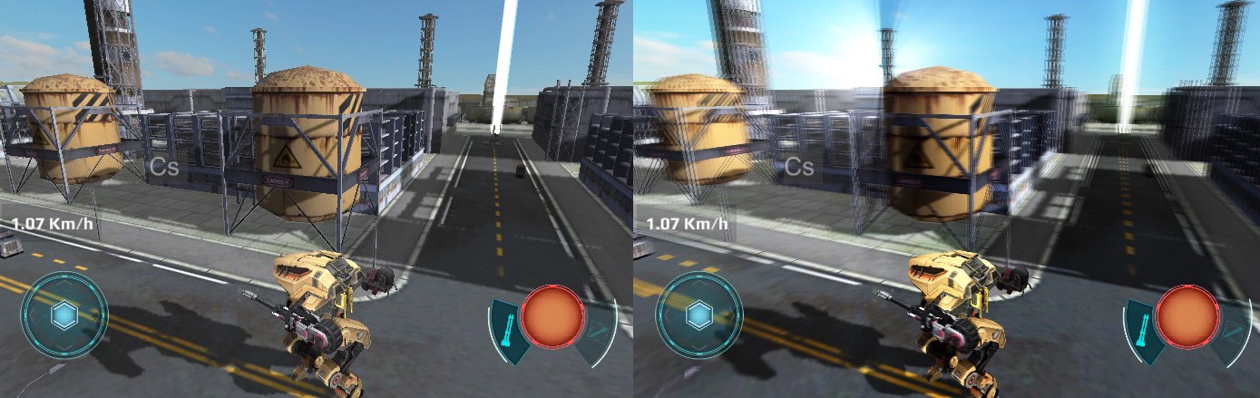
Exactlythis is what we did with the post-effect of light scattering from the sun [4]. We simplified the original prepass by replacing it with a billboard rendering with a sun texture. Billboard fragments hidden behind the scene objects were selected using a full-screen mask, which in combination serves as a shadow buffer for us (I will tell you more about rendering shadows a bit later).
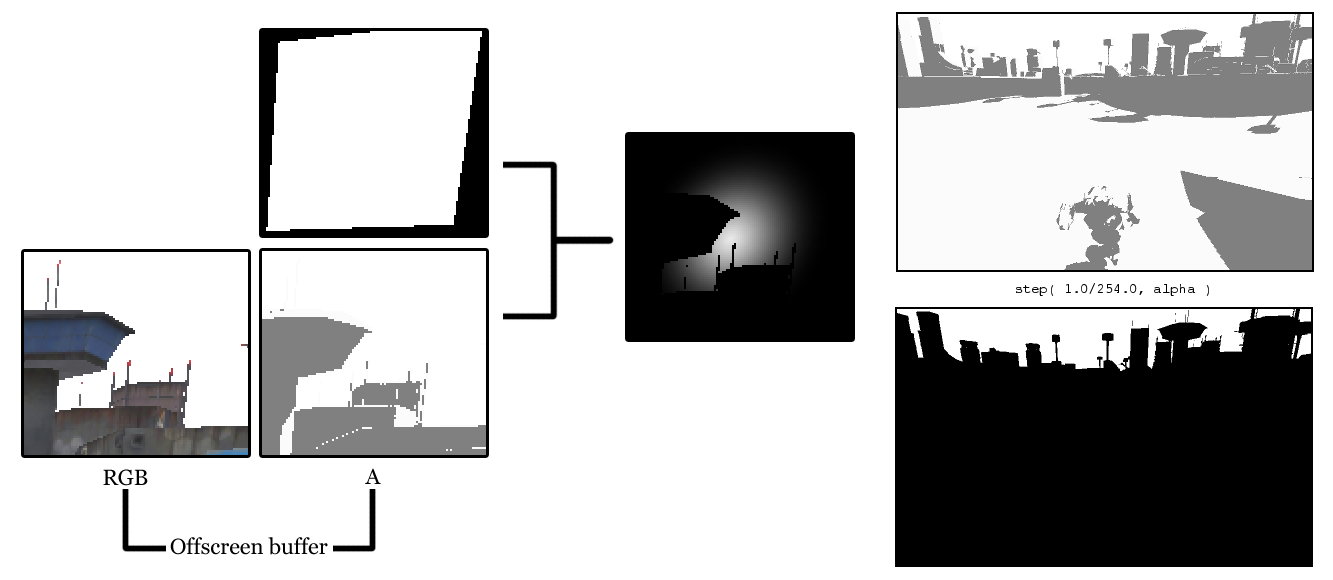
Right: a shadow buffer and a mask, which is obtained by applying a step function to it. All texels, whose alpha is less than 1, overlap the “sun”.
struct appdata
{
    float4 vertex : POSITION;
    half4 texcoord : TEXCOORD0;
};
struct v2f
{
    float4 pos : SV_POSITION;
    half4 screenPos : TEXCOORD0;
    half2 uv : TEXCOORD1;
};
#include “Unity.cginc”
sampler2D _SunTex;
sampler2D _WWROffscreenBuffer;
half4 _SunColor;
v2f vertSunShaftsPrepass(appdata v)
{
v2f o;
o.pos = mul(UNITY_MATRIX_MVP, v.vertex);
o.screenPos = ComputeScreenPos(o.pos);
o.uv = v.texcoord;
return o;
}fixed4 fragSunShaftsPrepass(v2f i) : COLOR
{
// Тексели _WWROffscreenBuffer с альфа-компонентом == 1
// не спроецированы на геометрию сцены
const half AlphaThreshold = 0.99607843137; // 1 - 1.0/255.0
fixed4 result = tex2D( _SunTex, i.uv ) * _SunColor;
half shadowSample = tex2Dproj(
_WWROffscreenBuffer,
UNITY_PROJ_COORD(i.screenPos)
).a;
return result * step( AlphaThreshold, shadowSample );
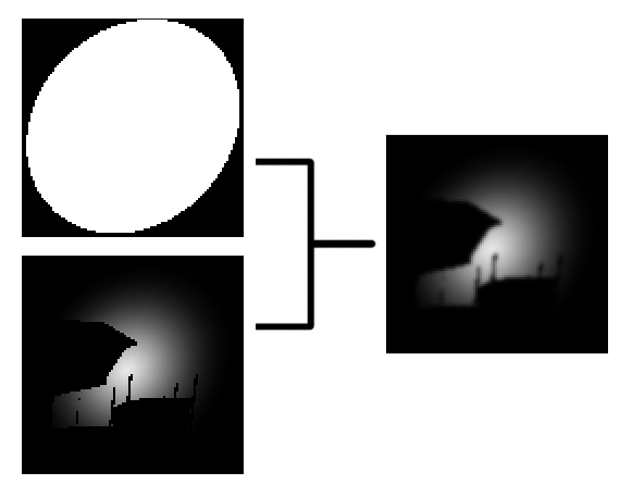
}Prepass texture smoothing is also performed by rendering a 3D model.
struct appdata
{
    float4 vertex : POSITION;
};
struct v2f
{
    float4 pos : SV_POSITION;
    half4 screenPos : TEXCOORD0;
};
#include “Unity.cginc”
sampler2D _PrePassTex;
half4 _PrePassTex_TexelSize;
half4 _BlurDirection;
v2f vertSunShaftsBlurPrepass(appdata v)
{
v2f o;
o.pos = mul(UNITY_MATRIX_MVP, v.vertex);
o.screenPos = ComputeScreenPos(o.pos);
o.uv = v.texcoord;
return o;
}fixed4 fragSunShaftsBlurPrepass(v2f i) : COLOR
{
half2 uv = i.screenPos.xy / i.screenPos.w;
half2 blurOffset1 = _BlurDirection * _PrePassTex_TexelSize.xy * 0.53805;
half2 blurOffset2 = _BlurDirection * _PrePassTex_TexelSize.xy * 2.06278;
half2 uv0 = uv + blurOffset1;
half2 uv1 = uv – blurOffset1;
half2 uv2 = uv + blurOffset2;
half2 uv3 = uv – blurOffset2;
return (tex2D(_PrePassTex, uv0) + tex2D(_PrePassTex, uv1)) * 0.44908 +
(tex2D(_PrePassTex, uv2) + tex2D(_PrePassTex, uv3)) * 0.05092;
}Of course, we went all the way: the final passage was also done by rendering a 3D model. And unlike in the previous cases, which can be replaced by a blinting in the viewport, the 3D model here contains additional data (vertex color), which are used in the effect shader.

struct appdata
{
    float4 vertex : POSITION;
    float4 color : COLOR;
};
struct v2f
{
    float4 pos : POSITION;
    float4 color : COLOR;
    float4 screenPos : TEXCOORD0;
};
#include “Unity.cginc”
sampler2D _PrePassTex;
float4 _SunScreenPos;
int _NumSamples;
int _NumSteps;
float _Density;
float _Weight;
float _Decay;
float _Exposure;
v2f vertSunShaftsRadialBlur(appdata v)
{
v2f o;
o.pos = mul(UNITY_MATRIX_MVP, v.vertex);
o.screenPos = ComputeScreenPos(o.pos);
o.color = v.color;
return o;
}float4 fragSunShaftsRadialBlur(v2f i) : COLOR
{
float4 color = i.color;
float2 uv = i.screenPos.xy / i.screenPos.w;
float2 deltaTextCoords = (uv - _SunScreenPos.xy) / float(_NumSamples) * _Density;
float2 illuminationDecay = 1.0;
float4 result = 0;
float4 sample0 = tex2D(_PrePassTex, uv);
for(int i=0; i<_NumSteps; i++)
{
uv -= deltaTextCoords * 2;
float4 sample2 = tex2D(_PrePassTex, uv);
float4 sample1 = (sample0 + sample2) * 0.5;
result += sample0 * illuminationDecay * _Weight;
illuminationDecay *= _Decay;
result += sample1 * illuminationDecay * _Weight;
illuminationDecay *= _Decay;
result += sample2 * illuminationDecay * _Weight;
illuminationDecay *= _Decay;
sample0 = sample2;
}
result *= _Exposure * color;
return result;
}Dynamic shadow optimization
Despite the computational complexity of post-effects, dynamic shadows are often even more resource-dependent. This is due not only to the computational complexity of the respective shaders, but also to the fact that obtaining smooth shadows requires an additional full-screen rendering pass.
Usually, a PCF filter is used to calculate the shading for a fragment of the image using the Shadow Mapping technique [5]. However, the result without additional smoothing gives only PCF with a very large kernel size, which is unacceptable for mobile platforms. The more advanced Variance Shadow Mapping method requires the support of partial differential approximation instructions and bilinear filtering for floating-point textures [6].
To obtain soft shadows, the entire visible scene is rendered twice - for the first time, only shadows are rendered into the offscreen buffer, then a smoothing filter is applied to the offscreen buffer, and after that the color of the objects is rendered on the screen, taking into account the influence of the shadow from the offscreen buffer. This leads to double loading of both the CPU (clipping, sorting, accessing the driver) and the GPU.
As one of the solutions to the problem, we decided to get rid of the double rendering of the scene without switching to the delayed lighting technique.
First, render the image into an intermediate buffer in the RGBA format (1). Alpha value is the ratio of the brightness of the color of a fragment if it was in the shadow to the brightness without a shadow (2). Then, using the command buffer, we take control at the moment the rendering of the opaque geometry is complete to take alpha from the buffer. Next, smooth (3), and modulate the smoothed shadows with color channels of the intermediate buffer (4). After that, the Unity pipeline resumes: transparent objects and a skybox are rendered (5).

This trick leads to a slight degradation of color reproduction in shaded places, but the tricks of computing what is written in alpha have reduced this effect to a minimum.
// shadow = 0..1
// spec - specular lighting
// diff - diffuse lighting
fixed4 c = tex2D( _MainTex, i.uv );
fixed3 ambDiffuse = c.xyz * UNITY_LIGHTMODEL_AMBIENT;
fixed3 diffuseColor = _LightColor0.rgb * diff + UNITY_LIGHTMODEL_AMBIENT;
fixed3 specularColor = _LightColor0.rgb * spec * shadow;
c.rgb = saturate( c.rgb * diffuseColor + specularColor );
c.a = Luminance( ambDiffuse / c.rgb );
As a result, we received a noticeable increase in productivity (10-15%) on medium-performance devices (mainly on androids), and heat transfer decreased on a number of devices. This technique is an intermediate solution, before switching to deferred lighting.
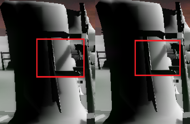
To shoot a promo, we still use a better option, as color degradation is undesirable there, and PC resources are enough. To improve the softness of the shadow in this case, we applied the following: when applying the shadow, a formula that takes into account LDotN is used, which allows for a smoother transition in bright places.
fixed shLDotN = lerp( clamp( shadow, 0, LDotN ), LDotN * shadow, 1 - LDotN);The fee for it is a small burn-out of the shadow in places where it becomes not completely black during bluering, but the result is a smoother transition of the partial shade.
References
[1] GPU Gems developer.nvidia.com/gpugems/GPUGems/gpugems_pref01.html
[2] Unity3D Post Processing Stack github.com/Unity-Technologies/PostProcessing
[3] Cache RenderTexture docs.unity3d.com/ScriptReference/RenderTexture.t
[4] Volumetric light scattering as Post-Process http.developer.nvidia.com/GPUGems3/gpugems3_ch13.html
[5] Percentage-close filtering http.developer.nvidia.com/GPUGems/gpugems_ch11.html
[6] Summed-Area Variance Shadow Maps http.developer.nvidia.com/GPUGems3/gpugems3_ch08.html
PS
Special thanks should be given to Igor Polishchuk, who, in fact, came up with all the tricks associated with shadows described here, and, in addition, participated in the writing of this article.