Two providers at the same time or Dual ISP with VRF on Cisco | Part 2

Good afternoon! HunterXXI inspired me to write this material in my article Two Providers at the Same Time or Dual ISP with VRF on Cisco . I became interested, studied the issue and put it into practice. I would like to share my experience in implementing Dual ISP on Cisco with the real use of two ISPs at the same time and, even, load balancing.
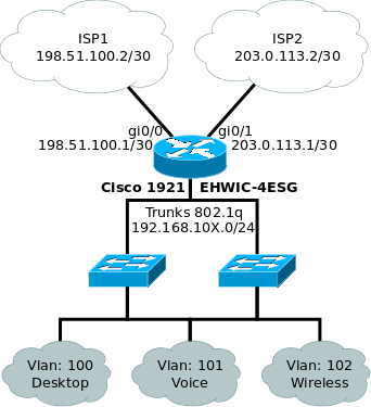
Demo scheme:
Description:
All actions are performed on the Cisco 1921 IOS Version 15.5 (3) M3 with the EHWIC-4ESG module installed.
- The ports GigabitEthernet0 / 0 and GigabitEthernet0 / 1 are used to connect the ISP.
- The GigabitEthernet0 / 0/0 and GigabitEthernet0 / 0/1 ports are configured in TRUNK and connected to the switches.
- To work with the local network, VLAN interfaces are used.
- This scheme provides three local IP networks 192.168.100.0/24 for VLAN 100, 192.168.101.0/24 VLAN 101 and 192.168.102.0/24 VLAN 102.
- In this example, VLAN 100 and 101 will be connected to each other but 101 will be without access to the Internet, and VLAN 102 will have access to the Internet only.
So it is conceived to show the possibilities of import / export between VRF.
The remaining physical ports are not involved, but nothing prevents you from using them at your own discretion.
Setting Gi0 / 0/0 and Gi0 / 0/1
interface GigabitEthernet0/0/0
 description TRUNK=>sw-access-1
 switchport mode trunk
 no ip address
end
interface GigabitEthernet0/0/1
 description TRUNK=>sw-access-2
 switchport mode trunk
 no ip address
end
VRF configuration
Cisco Express Forwarding Technology (CEF) - must be enabled for VRF to work.
Configure VRF for ISP
ip vrf isp1
 description ISP1
 rd 65000:1
 route-target export 65000:1
 route-target import 65000:100
 route-target import 65000:102
ip vrf isp2
 description ISP2
 rd 65000:2
 route-target export 65000:2
 route-target import 65000:100
 route-target import 65000:102
Please note that there is no 65000: 101 import in the configuration which will be assigned to VLAN 101. Thus, the isp1 and isp2 virtual routers will not have routes to the network 192.168.101.0/24
Configure VRF for VLAN
ip vrf 100
 description VLAN_Desktop
 rd 65000:100
 route-target export 65000:100
 route-target import 65000:1
 route-target import 65000:2
 route-target import 65000:101
ip vrf 101
 description VLAN_Voice
 rd 65000:101
 route-target export 65000:101
 route-target import 65000:100
ip vrf 102
 description VLAN_Wireless
 rd 65000:102
 route-target export 65000:102
 route-target import 65000:1
 route-target import 65000:2
Pay attention again to VRF 101, which does not exchange routes with ISP but exchanges with VRF 100.
From my own experience I was convinced that the name VRF for ISP is convenient to use as isp1 and isp2, the name VRF for VLAN should correspond to the VLAN number, all that identifies VRF is description. This is due to the fact that if, for example, you change one of the providers, then the entire reconfiguration will be reduced to changing the IP address of the interface and description.
Interface Configuration
You must use the ip vrf forwarding command on the interface before assigning an IP address. Otherwise, the IP address will be deleted and it will have to be reassigned.
Wan
interface GigabitEthernet0/0
 description ISP1
  ip vrf forwarding isp1
  ip address 198.51.100.1 255.255.255.252
  ip nat outside
interface GigabitEthernet0/1
 description ISP2
  ip vrf forwarding isp2
  ip address 203.0.113.1 255.255.255.252
  ip nat outside
LAN
interface Vlan100
 description VLAN_Desktop
 ip vrf forwarding 100
 ip address 192.168.100.254 255.255.255.0
 ip nat inside
interface Vlan101
 description VLAN_Voice
 ip vrf forwarding 101
 ip address 192.168.101.254 255.255.255.0
 ip nat inside
interface Vlan102
 description VLAN_Wireless
 ip vrf forwarding 102
 ip address 192.168.102.254 255.255.255.0
 ip nat inside
Remember to create the appropriate VLANs.
vlan 100
 name Desktop
 exit
vlan 101
 name Voice
 exit
vlan 102
 name Wireless
 exit
show vlan-switch
 VLAN Name                             Status    Ports
---- -------------------------------- --------- -------------------------------
1    default                           active
100  Desktop                           active
101  Voice                             active
102  Wireless                          active
interface Vlan1
 shutdown
BGP Configuration
router bgp 65000
bgp log-neighbor-changes
address-family ipv4 vrf 100
 redistribute connected
 maximum-paths 2
 exit-address-family
address-family ipv4 vrf 101
 redistribute connected
 exit-address-family
address-family ipv4 vrf 102
 redistribute connected
 maximum-paths 2
 exit-address-family
address-family ipv4 vrf isp1
 redistribute connected
 redistribute static route-map BGP_Filter
 default-information originate
 exit-address-family
address-family ipv4 vrf isp2
 redistribute connected
 redistribute static route-map BGP_Filter
 default-information originate
 exit-address-family
Each of the BGP address-family is configured separately for VRF and redistributes the connected routes (redistribute connected). We will have two routes by default, one through VRF isp1 and the second through isp2. The maximum-paths 2 option allows you to import both default routes into VRF 100 and 102.
It will look like this:
show ip route vrf 100
B*    0.0.0.0/0 [20/0] via 203.0.112.2 (isp2), 0d01h
                [20/0] via 198.51.100.2 (isp1), 0d01h
Cisco routers automatically balance traffic along routes in the same direction at the same cost.
In VRF, isp1 and isp2, in addition to redistribute connected, you must enable redistribute static and default-information originate, which will allow you to transfer the default gateway to other VRFs. You may notice that redistribute static is done via route-map BGP_Filter. This happens solely for reasons of aesthetic appearance of VRF routing tables defined in the local network so that routes to 8.8.8.8 and 80.80.80.80 do not fall into VRF routing tables 100 and 102.
Routing setup
Let's set up routing. One of the features of working with VRF, which complicates the configuration, is the need to define everything in a specific VRF.
ip route vrf isp1 0.0.0.0 0.0.0.0 198.51.100.2 tag 100 track 100
ip route vrf isp2 0.0.0.0 0.0.0.0 203.0.112.2 tag 100 track 200- tag - helps us to filter only these routes for transmission to local VRFs
- track - indicates which object is responsible for the health of the route
route-map BGP_Filter permit 10
 description Fix BGP static redistribution
 match tag 100
Using this route-map and applying it in VRF for ISP, only routes with a tag will be redistributed, and the rest will remain only inside ISP VRF.
ip route vrf isp1 8.8.8.8 255.255.255.255 198.51.100.2
ip route vrf isp1 80.80.80.80 255.255.255.255 198.51.100.2
ip route vrf isp2 8.8.8.8 255.255.255.255 203.0.112.2
ip route vrf isp2 80.80.80.80 255.255.255.255 203.0.112.2
Separate routes to the hosts 8.8.8.8 and 80.80.80.80 are necessary so that when the track works and disconnects the default gateway, we still have the opportunity to check the availability of these addresses. Since we do not assign a tag to them, they will not fall under the route-map and redistributed.
NAT setup
For NAT to work, you need to designate inside, outside interfaces. As outside we define the interfaces that the ISP is connected to using the ip nat outside command. All other interfaces that relate to the LAN are denoted as inside by the ip nat inside command.
It is necessary to create two route-maps in which the interfaces isp1 and isp2 are defined
route-map isp1 permit 10
 match interface GigabitEthernet0/0
route-map isp2 permit 10
 match interface GigabitEthernet0/1
NAT rules must be specified for each VRF through each ISP. Since in our condition Vlan 101 does not have access to the Internet, there is no need to specify the rules for it, and even if you specify them, it won’t work, because there is no routing.
ip nat inside source route-map isp1 interface GigabitEthernet0/0 vrf 100 overload
ip nat inside source route-map isp2 interface GigabitEthernet0/1 vrf 100 overload
ip nat inside source route-map isp1 interface GigabitEthernet0/0 vrf 102 overload
ip nat inside source route-map isp2 interface GigabitEthernet0/1 vrf 102 overload
A bit of NAT theory
Cisco has many flavors of NAT. In Cisco terminology, what we use is called Dynamic NAT with Overload or PAT.
What is needed for NAT to work?
In a simple NAT configuration, it is enough to create an access-list in which to define a local network and apply a translation rule.
Thus, we indicate that / in which we include the broadcast, that is, we fulfill all the necessary requirements.
This is a simple configuration setting, it is obvious and understandable without additional details.
The rule that we apply in our configuration is not so obvious. As we recall, route-map isp1 defines the GigabitEthernet0 / 0 interface. To paraphrase a command, something similar
It turns out that you need to translate the source traffic of which GigabitEthernet0 / 0?
In order to understand this, you need to immerse yourself in the mechanism for passing the packet inside the router.
What is needed for NAT to work?
- Define internal and external interfaces
- Indicate that we want to broadcast
- Indicate what we want to broadcast
- Enable Broadcast
In a simple NAT configuration, it is enough to create an access-list in which to define a local network and apply a translation rule.
ip access-list extended NAT
 permit ip 192.168.0.0 0.0.0.255 any
ip nat inside source list NAT interface GigabitEthernet0/0 overload
Thus, we indicate that / in which we include the broadcast, that is, we fulfill all the necessary requirements.
This is a simple configuration setting, it is obvious and understandable without additional details.
The rule that we apply in our configuration is not so obvious. As we recall, route-map isp1 defines the GigabitEthernet0 / 0 interface. To paraphrase a command, something similar
ip nat inside source GigabitEthernet0/0 interface GigabitEthernet0/0 overload in vrf 100It turns out that you need to translate the source traffic of which GigabitEthernet0 / 0?
In order to understand this, you need to immerse yourself in the mechanism for passing the packet inside the router.
- Traffic that arrives at an interface that is marked as inside is not broadcast. It is labeled as possibly broadcast.
- The next step in processing this traffic is to route it according to the routing table or PBR.
- If, according to the table, traffic gets to the interface that is marked as outside, it is broadcast.
- If traffic falls on a non outside broadcast interface does not occur.
Mistakenly, you might think that you can do route-map LAN match interface Vlan100. Use this as ip nat inside source route-map LAN, etc.Thanks to IlyaPodkopaev NAT on Cisco. Part 1
To avoid this thought, you need to understand that this translation rule is triggered when the traffic is already on the outside interface and the match interface where this traffic is no longer leads to nothing.
SLA setup
ip sla auto discovery
ip sla 10
 icmp-echo 198.51.100.2
 vrf isp1
 frequency 5
ip sla schedule 10 life forever start-time now
ip sla 11
 icmp-echo 8.8.8.8
 vrf isp1
 frequency 5
ip sla schedule 11 life forever start-time now
ip sla 12
 icmp-echo 80.80.80.80
 vrf isp1
 frequency 5
ip sla schedule 12 life forever start-time now
ip sla 20
 icmp-echo 203.0.112.2
 vrf isp2
 frequency 5
ip sla schedule 20 life forever start-time now
ip sla 21
 icmp-echo 8.8.8.8
 vrf isp2
 frequency 5
ip sla schedule 21 life forever start-time now
ip sla 22
 icmp-echo 80.80.80.80
 vrf isp2
 frequency 5
ip sla schedule 22 life forever start-time now
There is nothing special in the configuration, accessibility via ICMP nodes 8.8.8.8 80.80.80.80 and provider routers from each ISP VRF will be checked.
Track setup
track 100 list boolean and
 object 101
 object 110
track 101 ip sla 10 reachability
 delay down 20 up 180
track 102 ip sla 11 reachability
 delay down 20 up 180
track 103 ip sla 12 reachability
 delay down 20 up 180
track 110 list boolean or
 object 102
 object 103
track 200 list boolean and
 object 201
 object 210
track 201 ip sla 20 reachability
 delay down 20 up 180
track 202 ip sla 21 reachability
 delay down 20 up 180
track 203 ip sla 22 reachability
 delay down 20 up 180
track 210 list boolean or
 object 202
 object 203
track 1000 stub-object
Logic of work:
In the routing table there is a route ip route vrf isp1 0.0.0.0 0.0.0.0 198.51.100.2 tag 100 track 100 which is tied to track 100.
- If track 100 is in UP state, then there is a route in the table.
- Object 100 is boolean and, which means that UP it will be considered if all its objects are in UP state.
- If any of the objects is 100 DOWN, then the message of the object 100 will be DOWN.
- It contains objects 101 and 110.
- Object 101 corresponds to SLA 10 - checks the provider's gateway.
- Object 110 combines 102 and 103 as boolean or, which means it will be UP if at least one of its UP objects.
- Objects 102 and 103 check 8.8.8.8 and 80.80.80.80, respectively, they need two to exclude false positives.
Thus, it turns out that if the default gateway of the provider meets at least one of the external addresses, then the connection is considered working.
track 1000
track 1000 stub-object
 default-state down
This object defaults to DOWN.
In this configuration, this object is necessary in order to force disconnect one of the ISP and not connect it. To do this, track 1000 must be added to an object of 100 or 200. Based on boolean and, if one of the objects is DOWN, then the entire object is considered DOWN.
EEM Setup
EEM - Embedded Event Manager allows you to automate actions in accordance with specific events.
In our case, when one of the ISP stops working, it will be excluded from the routing table. But NAT translation rules will remain. Because of this, already established user connections will hang until the NAT translation is cleared by timeout.
In order to speed up this process, we need to clear the NAT table with the clear ip nat translation * command and it is best to do this automatically.
event manager applet CLEANNAT-100
 event track 100 state down
 action 10 cli command "enable"
 action 20 cli command "clean ip nat translation *"
event manager applet CLEANNAT-200
 event track 200 state down
 action 10 cli command "enable"
 action 20 cli command "clean ip nat translation *"
If objects 100 or 200 go into the DOWN state, then action commands will be executed in order.
tips and tricks
I want to note a few more features of working with VRF.
For example, NTP configuration:
ntp server vrf isp1 132.163.4.103Due to the use of VRF, any network operations need to be assigned to a virtual router, this is due to the fact that when you configure this configuration and perform show ip route you will not see any entries in the routing table.
ping vrf isp1 8.8.8.8Be careful.
The advantages of this configuration I would like to include its flexibility. You can easily bring out one VLAN through one ISP, and another through the second.
Disadvantages, and this is a question for the respected public, when one of the ISPs falls off, then the clear ip nat translations * command disconnects all connections, including with a working ISP. As practice has shown, in those cases when the provider falls off, users do not notice this “cliff” or it is not critical.
If someone knows how to partially clear the translation table, I will be grateful.
PS>
Remember to disable NAT translation to private subnets.
ip access-list extended NO_NAT
deny ip any 192.168.0.0 0.0.255.255
deny ip any 172.16.0.0 0.15.255.255
deny ip any 10.0.0.0 0.255.255.255
permit ip any any
route-map isp1 permit 10
match ip address NO_NAT
match interface GigabitEthernet0/0