March 1, 2017 at 09:52
How custom solutions helped save on network infrastructure
- Transfer

The construction of the CDN infrastructure is associated with a large number of technical issues: from choosing equipment and installing it in data centers to the user interface for interacting with the network capabilities. We provide a translation of an article from the Fastly blog, where the team talks about very interesting custom solutions for working with the network (a significant part of which was independently used in the Airy infrastructure ).
As a result of infrastructure optimization, it was possible to achieve minimal downtime in case of failure of a node and large scalability of the system.
Scaling
Gradually developing CDN is not easy, since the very essence of the service involves customers with an extensive geography of requests. Therefore, Fastly initially focused on what was missing in the industry: maximum transparency and control over how content is delivered at the “frontier”.
When we first started, our lack of experience in network technologies had little effect. Our typical point of presence (POP) consisted of two hosts directly connected to providers via BGP (Border Gateway Protocol). By the beginning of 2013, we had grown so much that this number of hosts was no longer enough.
Scale our topology by connecting even more caches directly to providers, as shown in Fig. 1 (a) was not allowed. Providers do not want to work this way because of the cost of the ports and the difficulty of setting up additional BGP sessions.
Fig. 1. Influence of scalable network topology.
An obvious solution could be a network device, as shown in Fig. 1 (b). Although this could be an acceptable compromise, the nature of the CDN is such that it implies a continuous increase in geographic coverage and traffic.
Today, our smallest points of presence include two network devices, as shown in fig. 1 ©. How it works is shown in fig. 2. The router receives routes directly from providers through BGP and inserts them into the FIB (Forwarding Information Base). A lookup table implemented in hardware is used to select a route. Hosts direct traffic to the router, which redirects packets to the most suitable next section of the network, according to a search in the device’s FIB.
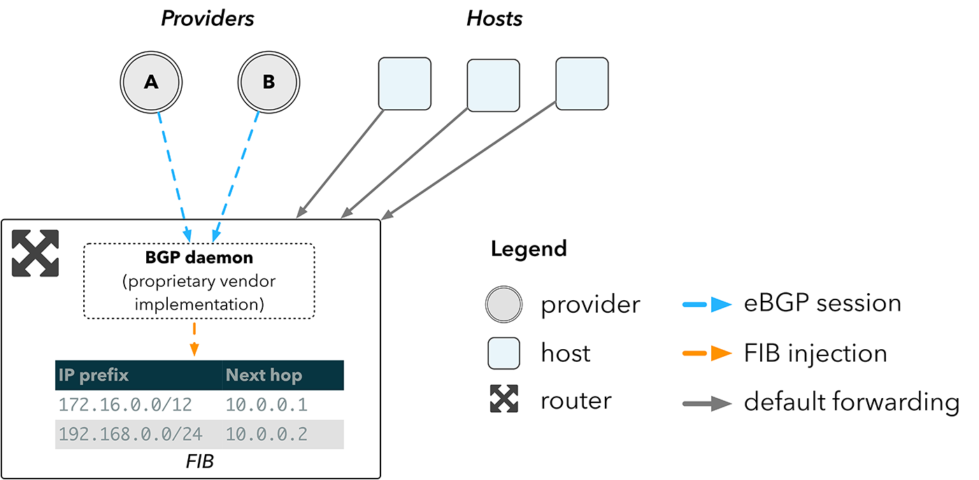
Fig. 2. Network topology using a router
The larger the FIB, the more routes the device can store. Border routers should be able to store a routing table for the entire Internet, which now exceeds 600,000 entries. The hardware that is required to store such a FIB forms the bulk of the cost of the router.
Routing without routers
In traditional cloud environments, the cost of edge routers quickly becomes negligible against the backdrop of the sheer volume of servers and switches that they serve. But CDNs must have a large number of profitably located points from where they deliver content. Therefore, network devices can account for a significant share of CDN infrastructure costs.
We did not like the idea of spending several million dollars on a very expensive network hardware. We would rather invest this money in regular servers, which are directly responsible for how efficiently we deliver content.
You could use the switches, but they have a very limited FIB - about tens of thousands of routes, which is much less than we need. By 2013, vendors such as Arista began to implement functionality that would help us deal with this limitation. Vendors began to let us run our own software on switches.
Instead of relying on FIB in a network device, we could forward traffic to hosts. BGP sessions from our providers would still be terminated on the switches, but the routes would then go to the hosts.
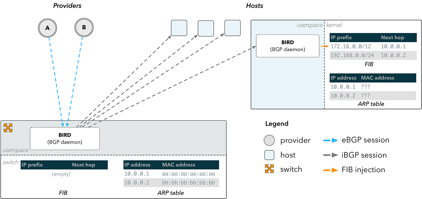
Fig. 3. Reflection of BGP routes
External BGP sessions (eBGPs) are terminated on a BGP daemon, such as a BIRD, that is running on the switch. The resulting routes are then sent through internal BGP sessions (iBGP) to the BIRD running on the hosts, which then inserts the routes directly into the host core.
This solves the problem of bypassing the FIB on the switch, but not the problem of how to send packets back to the Internet. The entry in the FIB consists of the prefix of the destination and the address of the next network section. To send a packet to the next section, the device must know its physical address on the network. This data is stored in the Address Resolution Protocol Protocol (ARP) table.
In fig. Figure 3 shows that the switch has the correct ARP information for our providers, since it is connected directly to them. Hosts do not possess it and therefore cannot determine the next network section for what was sent to them via BGP.
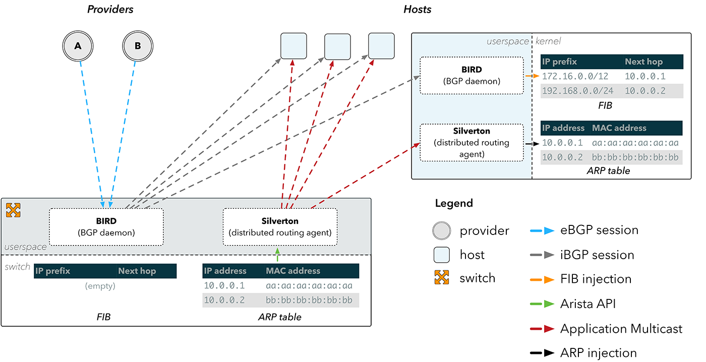
Fig. 4. Distributing ARP with Silverton
Silverton - Distributed Routing Agent
This has led to the advent of Silverton, our own network controller that controls routing at our points of presence. We realized that we can simply run the daemon on the switch, which learns about changes in the ARP table through the API on Arista devices. Having learned about the change in the physical MAC address of the provider, Silverton then distributes this information over our network, and the clients on the hosts reconfigure our servers taking into account the information on how to directly reach the providers.
Having the IP and MAC addresses of the provider, the first step for Silverton on the client side is to “trick” the host so that it “believes” that this IP address is directly accessible through the interface or local link. This can be achieved by configuring the provider IP address as “peer” in the interface via iproute:
$ ip addr add peer 10.0.0.1 dev eth0 If the host considers the provider IP address to be a local link, it will look for its MAC address in the ARP table. This can also be corrected:
$ ip neigh replace 10.0.0.1 lladdr aa:aa:aa:aa:aa:aa nud permanent dev eth0Now, each time a route search will return the next section as 10.0.0.1, and traffic will be sent to aa: aa: aa: aa: aa: aa directly.
The switch receives data frames from the host to the physical MAC address, which, as you know, is connected directly. The switch can determine which interface to send the frame to by looking at the local MAC address table, which shows the correspondence of the destination MAC address and the outgoing interface.
Although the process described may seem quite complicated, our first version of Silverton contained less than 200 lines of code. And that saved us hundreds of thousands of dollars at every point of presence that we deployed. Over time, Silverton "grew" and began to provide the entire dynamic configuration of the network: from naming description fields to manipulating routing announcements and emptying BGP sessions.
In addition, Silverton provided a valuable level of abstraction. He maintained the illusion that each host was directly connected to each provider, which was our starting point (Figure 1 - Option A). By supporting several routing tables in the kernel and choosing which one to use for each package, we were able to create tools and applications on top of Silverton. An example is the st-ping utility, which pings destinations for all connected providers.

Fig. 5. Ping for all transit providers at the point of presence
Prerequisites for Faild
Since we have already seen that getting rid of traditional network devices can significantly reduce capital costs, we paid attention to load balancers.
Traditionally, the load was distributed exclusively using balancers or ECMP routers. Recently, the opposite approach has begun to gain strength, in particular, services such as MagLev and GLB are balancing using software running on hosts.
Our development Faild is a synthesis of two approaches, where we use hardware processing on traditional switches wherever possible, and transferring processing to hosts where necessary. The result of this approach is a distributed balancer.
Balancing client requests: tightrope walking
Imagine a set of servers that serves a number of clients, as shown in Fig. 6. From the point of view of the client, which server served his request, it does not matter until the response is received quickly enough. This gives flexibility in matching which requests are processed by which resources. This is called load balancing and is performed on almost every level of the network stack. Here we focus on balancing incoming client requests in the context of CDN.
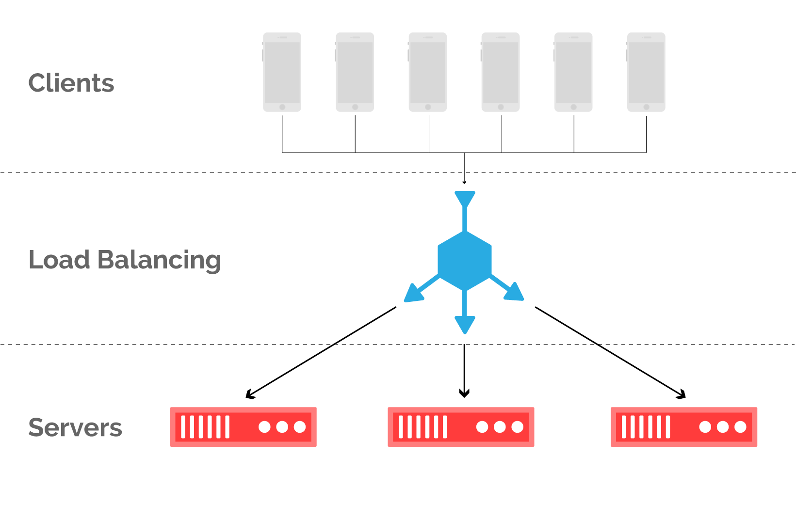
Fig. 6. When balancing, client requests are mapped to cache servers at the point of presence. The
main problem with balancing http requests is the inevitable limitation: if a packet from an established TCP connection is redirected to the wrong server, the corresponding TCP stream will be dropped.

Fig. 7. The topology of the network using the balancer (a) and the corresponding packet stream (b)
Balancers usually work as proxies, terminate connections from clients and direct traffic to the backend servers, as shown in Fig. 7 (a).
The balancer can monitor the status of the backend servers to decide where to direct incoming streams. With proper implementation, the distribution of requests across backend servers is close to optimal, but it is very expensive. The balancer monitors the status of each network connection, and this is a difficult task, for which specialized hardware is often used.
However, maintaining connection status information is an additional complication. As you know, it is easier for a sender to create connections than a recipient for tracking them, and this asymmetry in TCP is regularly used during DOS attacks. Most balancers contain additional tools to prevent SYN floods, but they are still a bottleneck in the network. Even virtualized balancers that run on common hardware, such as Google MagLev, require monitoring the status of streams, and therefore DOS attacks are also dangerous for them.
DNS: bypass option
DNS turns names into addresses, and this can be used to balance the load between servers if only the IP addresses of normally functioning servers are returned.

Fig. 8. The architecture of server selection via DNS (a) and the corresponding packet stream (b)
This approach does not require monitoring the status of flows and therefore scales well. However, it has a fundamental limitation in terms of failover. The DNS response can be cached by downstream resolvers for minutes, and sometimes even hours. The response caching period is passed through the TTL field in the response, but this is not always taken into account by resolvers. Therefore, propagating the change can take a considerable amount of time, during which the client will be connected to the idle server.
Companies such as Spotify or Netflix can control both the end-user application and the servers at the border, and therefore can circumvent this problem with DNS by embedding server choice in their applications. CDNs like Fastly cannot do this because they have to work with a lot of options - from video streaming to API calls. The only thing that is known for certain is that the request will be made over HTTP.
ECMP: Lesser Evil
Another well-known alternative is ECMP (Equal Cost Multi-Path). ECMP maps the following network sections to the same destination prefix, and the choice of this section is determined by hashing the fields in the header of the forwarded packet. By calculating the hash from such fields that do not change over the lifetime of the stream (source address, destination, and ports), we can be sure that all packets of the stream are sent to the same next section of the network.
Servers can signal via BGP their availability to a connected switch that hashes packets.
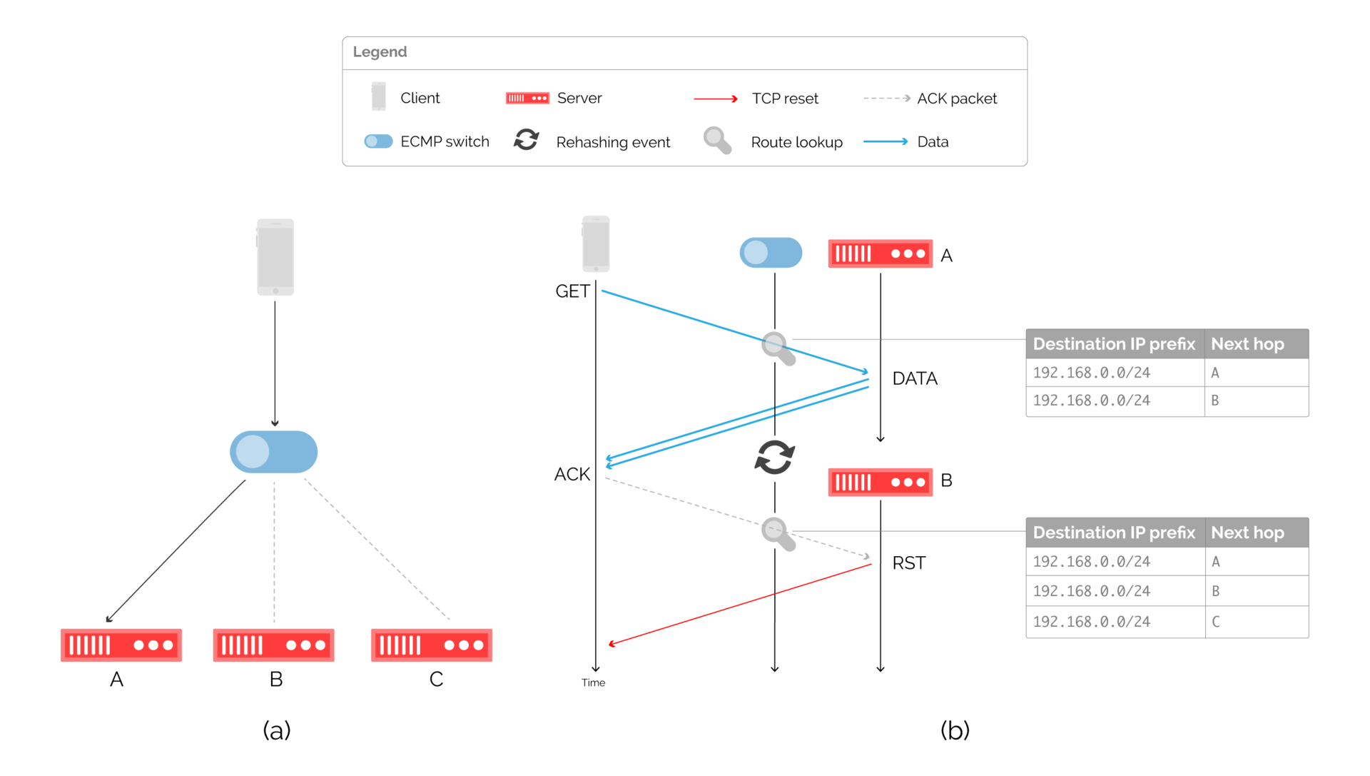
Fig. 9: Balancing through the ECMP switch and the corresponding packet stream at the time of re-hashing.
The disadvantage of this approach is that until recently, manufacturers did not maintain the constancy of hashing in ECMP. If the route was changed due to the addition or exclusion of the server, the result of the hashing could change, due to which packets could be sent to another server. This situation is shown in fig. 9 (b).
Despite this, ECMP remains a popular approach in the CDN industry. Refusing to monitor states, ECMP works well with stable operation of servers, creating instead problems with connections when changing states.
Elastic ECMP: First Approach
Re-caching occurs when the route information (the following network sections) changes. A possible alternative would be to use ARP tables as a workaround. By specifying the following static sections of the network in the routing table, we can force the switch to search the ARP table. We can also reconfigure the ARP table to influence packet forwarding.
There are two problems:
- We can no longer use routing protocols such as BGP or OSPF to direct traffic to servers. Conventional routing protocols provide accessibility by modifying the routing table, but our approach takes traffic control to the connection layer. We must write a controller that directly modifies the ARP table on the switch, as shown in Figure 10. The controller exchanges information with agents running on connected caches. Each agent checks the status of the local Varnish entity, which processes http requests from end clients.
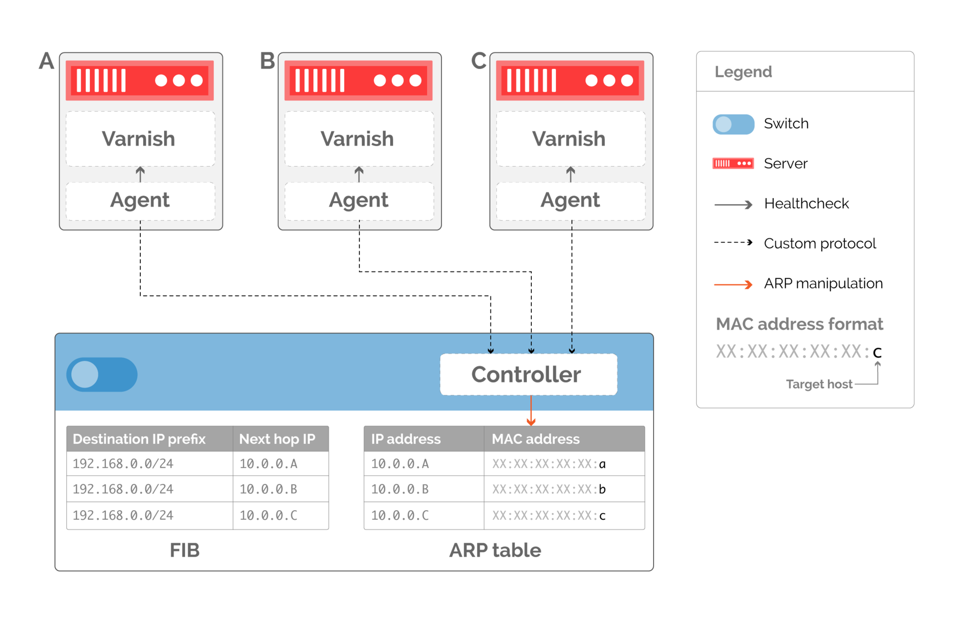
Fig. 10. Custom routing protocol based on changing the ARP table. The routing table remains constant, and the ARP table changes to indicate available servers - The depth of detail with which we can balance traffic is now directly related to the number of the following network sections in the routing table. As shown in fig. 10, if we delete the server that serves the traffic, we need to rewrite the ARP record so that it points to an available server, potentially doubling the traffic to another server. To avoid this, we can create the following several sections of the network, as shown in Fig. 11. If we have two virtual next sections of the network on each server, then the available servers will have an equal number of ARP records pointing to them when server B stops working.
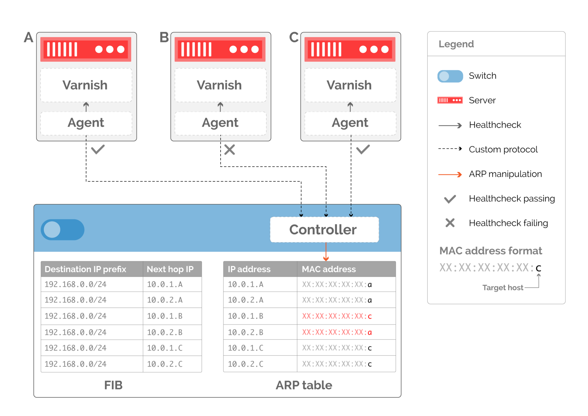
Fig. 11. The following additional sections of the network provide an even distribution of traffic when server B stops working
Faild: bypass layer
An “elastic” ECMR still cannot provide an accurate output of the server from the number of workers. Back to fig. 11. If host B fails, this will cause traffic to go to all the remaining servers. All existing connections will be reset.
It is believed that this is inevitable, and it is worth accepting, as this is caused by rare phenomena of hardware failure or software problems. However, in practice, servers are often taken out of production to upgrade software. Dropping connections because of this causes not only a temporary traffic problem. This makes it difficult to quickly introduce new software, as each upgrade will lead to problems.
Correct failure processing cannot be implemented only on the switch, because it does not “know” which flows are active at any given time. Our solution was to distribute state tracking between the controller and hosts. For this, we developed our own Faild solution.
The first step to tidying the server out of production is to signal it. Although our previous examples suggested that the host interface has only one MAC address, in practice there is no such restriction. We can enter in the ARP table on the switch not only information about the previously working host, but also about the new one (Fig. 12).
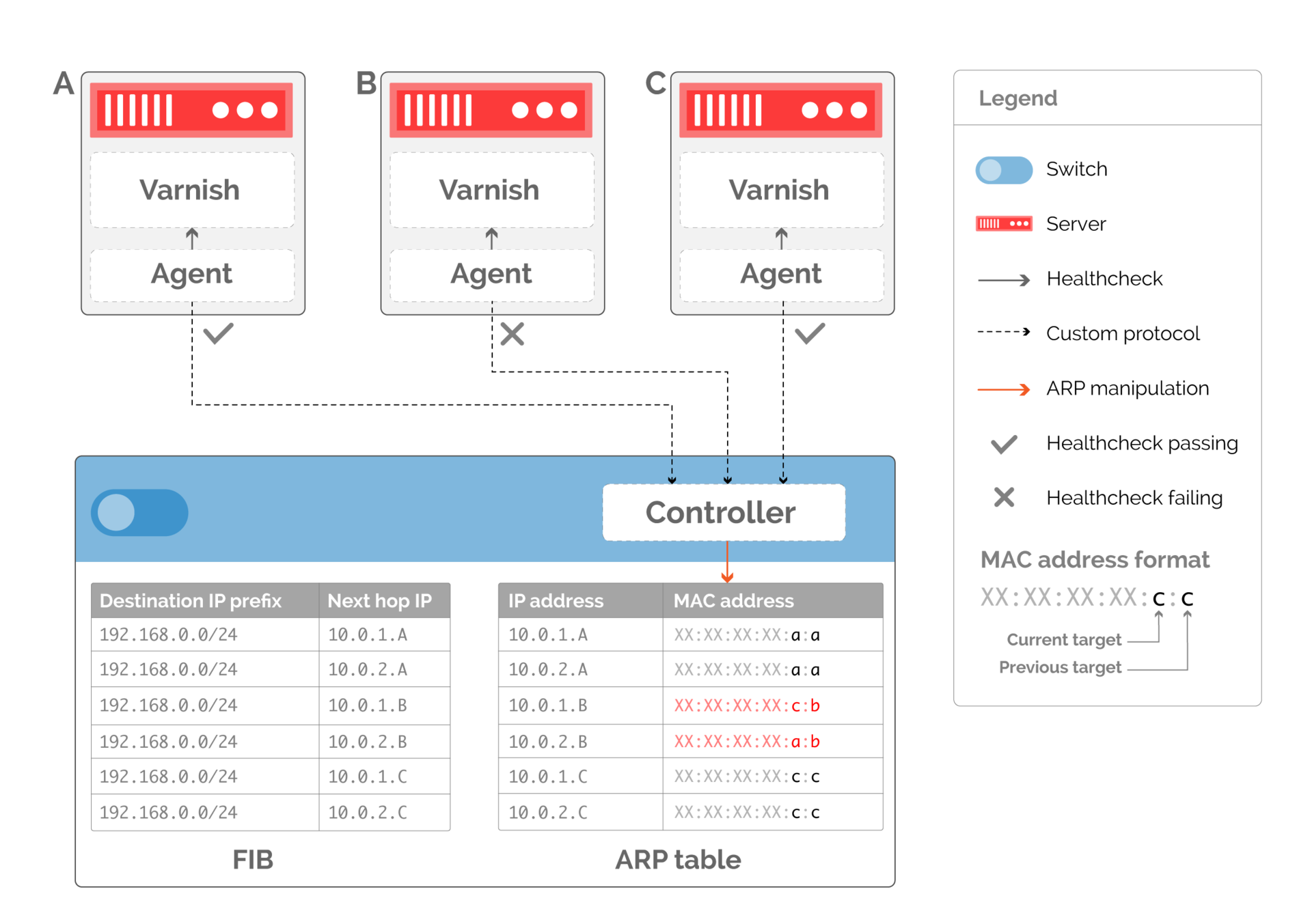
Fig. 12. Host encoding to replace idle through MAC addresses
Now that we have passed the availability information to the switch, we can delegate the balancing decision to the servers. This not only eliminates the need to monitor the status of streams in the network. It also transfers the computational burden to servers, which are more at the point of presence than switches.
This computational burden is reduced through the implementation of host processing as a separate kernel module. It efficiently processes incoming packets according to the destination MAC address (see Figure 13).
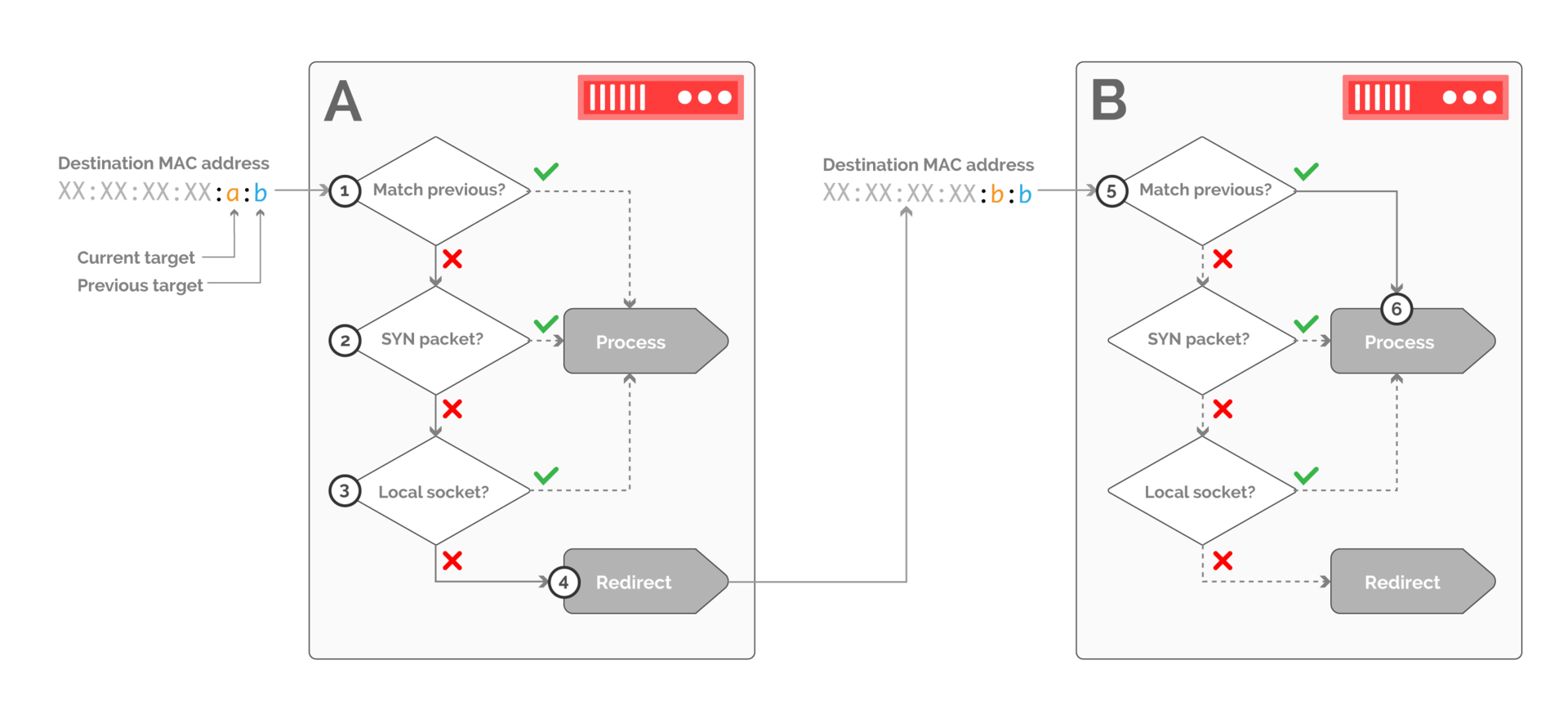
Fig. 13. An example of packet processing on the receiving side when traffic is transferred from host B to host A. Packets are filtered on host A and are received only if they belong to a new connection or correspond to a local TCP socket
The kernel module of the receiving host must first determine if the previous destination matches this host. If yes, then the processing is transferred to the local network stack. If not, you need to make sure that the packet belongs to the new connection (through the SYN flag in the TCP header - step 2), or to the existing connection, which can be done by searching the socket table (step 3).
If none of these conditions are met, the packet is redirected to the previous destination by rewriting the MAC header.
The same logic applies to host B (step 5). In this case, the host indicated as the previous destination corresponds to the host, so the packet is accepted.
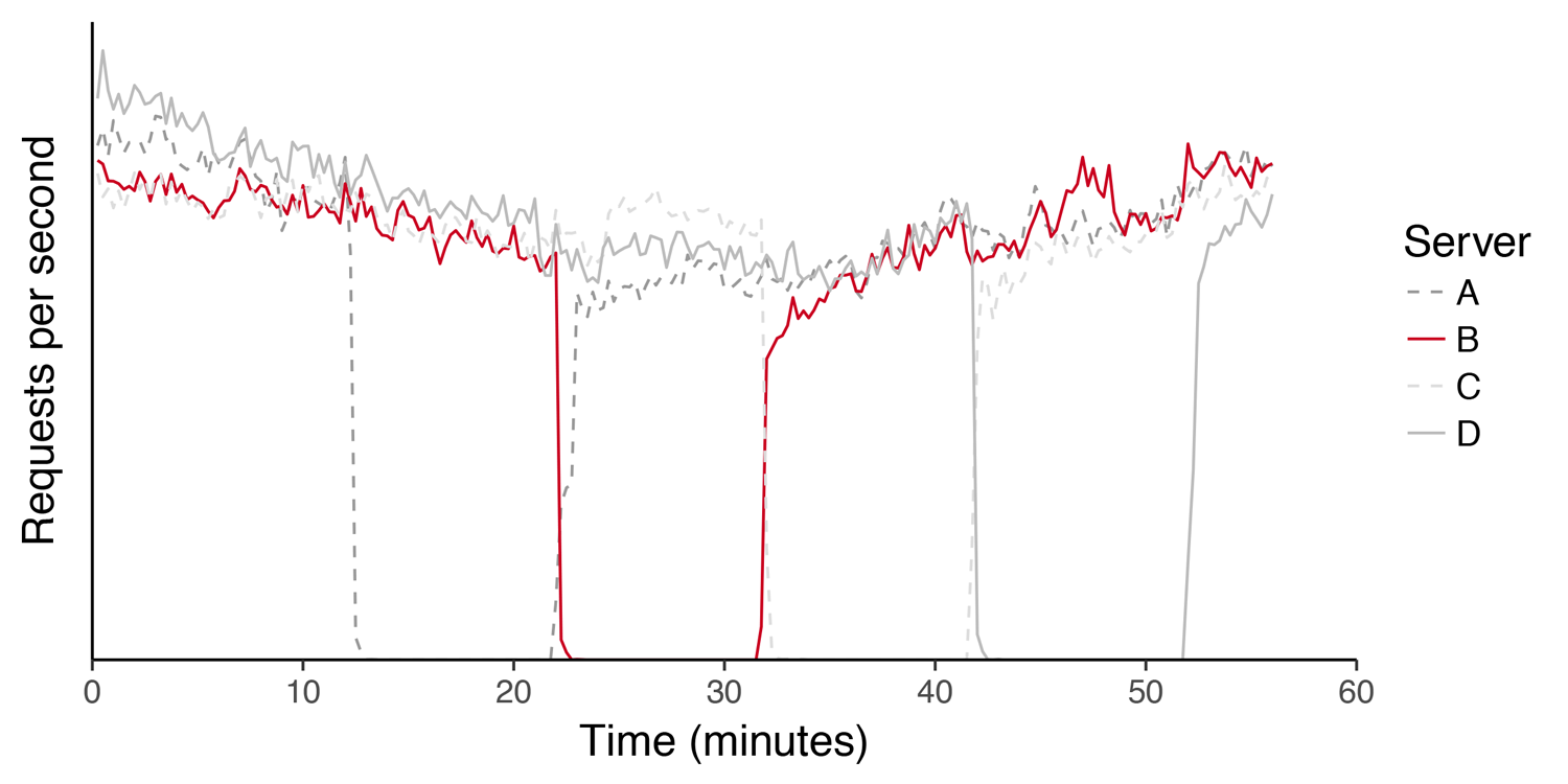
Fig. 14. The load graph (requests per second) on a server cluster during a sequential kernel upgrade. Hosts leave and return to production without affecting the service.
Implementation of Faild over the past 3 years has affected not only traffic. By reducing the negative impact of the necessary work on servers, Faild allowed us to deploy new software faster, without affecting clients, and also accelerate our reaction to vulnerability detection.
Summary
Fastly has reached the volume measured in millions of requests per second since the Faild solution was introduced in 2013. A significant contribution to this was made by “elastic” balancing, which reduces the cost of network reconfiguration without loss for users.
Through combining ECMP, rewriting ARP, and manipulating the kernel, this growth was supported by custom solutions, without acquiring anything more complicated than conventional switches.