Configuring VLAN on the routerOS operating system
For a good example, I will use the Mikrotik CCR1036-8G-2S + router and the CRS125-24G-1S switch.
This option currently works in several hotels in Moscow and the Moscow region.
We set the conditional task so that on each switching node there is a class A network (10.1.0.0/24) for company employees and a class C network (192.168.1.0/24) for WiFi for visitors.
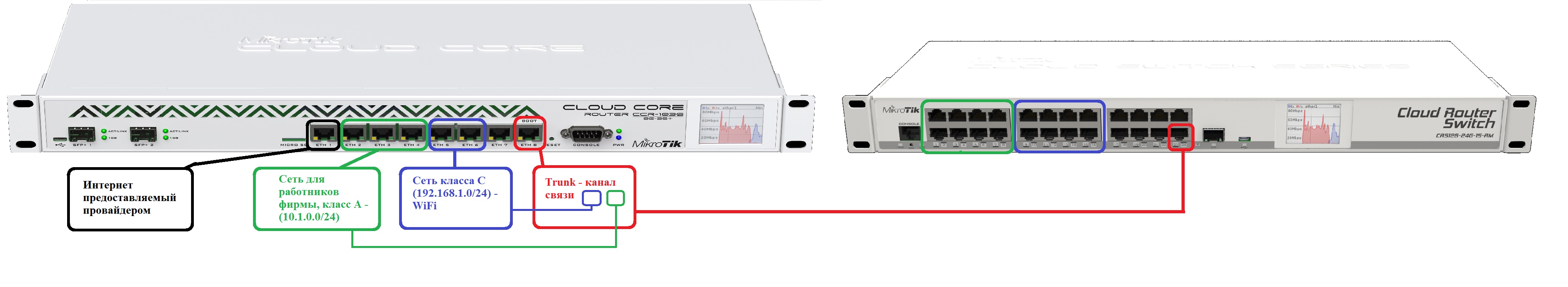
Suppose we have a switching node A with a Mikrotik CCR1036-8G-2S + router, a switching node B with a CRS125-24G-1S switch. Switching nodes A and B will be connected by a communication channel (Trunk) in our case over a twisted pair cable (there may be several communication channels (trunk) depending on the number of switching nodes; also if there is a fiber optic link and an SFP mikrotik optical module, you can assign trunk to SFP). Below is a twisted-pair trunk diagram.
Let's set up switching node A with the Mikrotik CCR1036-8G-2S + router.
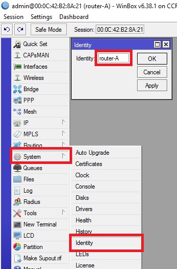
Let's call our router “router-A”.
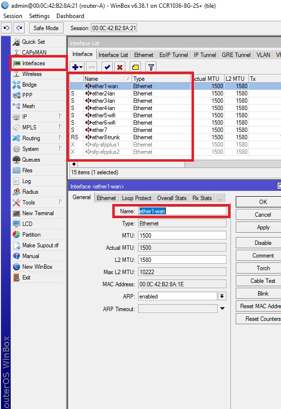
We denote the physical ports so that there is no confusion about which networks they belong to. Let lan denote the physical ports that will belong to the network (class A) 10.1.0.0/24, wifi denote the physical ports that will belong to the network (class A) 192.168.1.0/24 and trunk the physical ports that will be used for the communication channel type trunk.
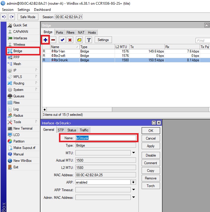
Create virtual interfaces in the bridge tab, to combine LAN ports.
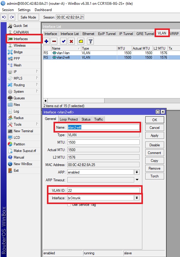
We create Vlan interfaces with the help of which the 10.1.0.0/24 and 192.168.1.0/24 networks will be transported to the switching node B via the trunk communication channel. VLAN id for network 10.1.0.0/24 will be 11 , and for network 192.168.1.0/24 it will be 22 . Using these id information will be transmitted on the traffic belonging to vlan1-lan and vlan2-wifi.
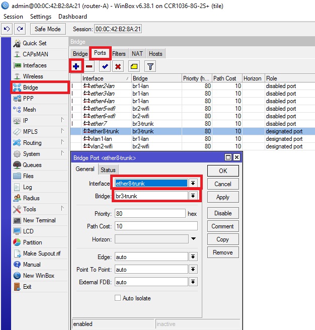
Assign LAN ports of the router to virtual interfaces (bridge) according to the above scheme
(I will add this LAN port for a possibly future switching node C, for every fireman)
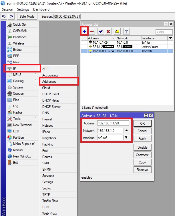
Assigning Networks to Virtual Interfaces
The provider provides me with the Internet protocol EOiP. Therefore, you do not pay attention to this command, but configure the Internet access via the wan port according to the settings provided by your provider
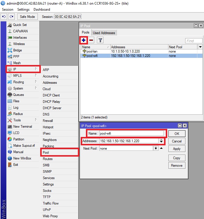
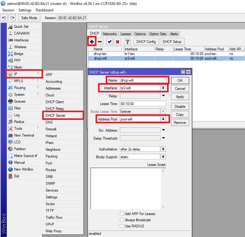
Set up a pool of distributed addresses for networks, set up dhcp
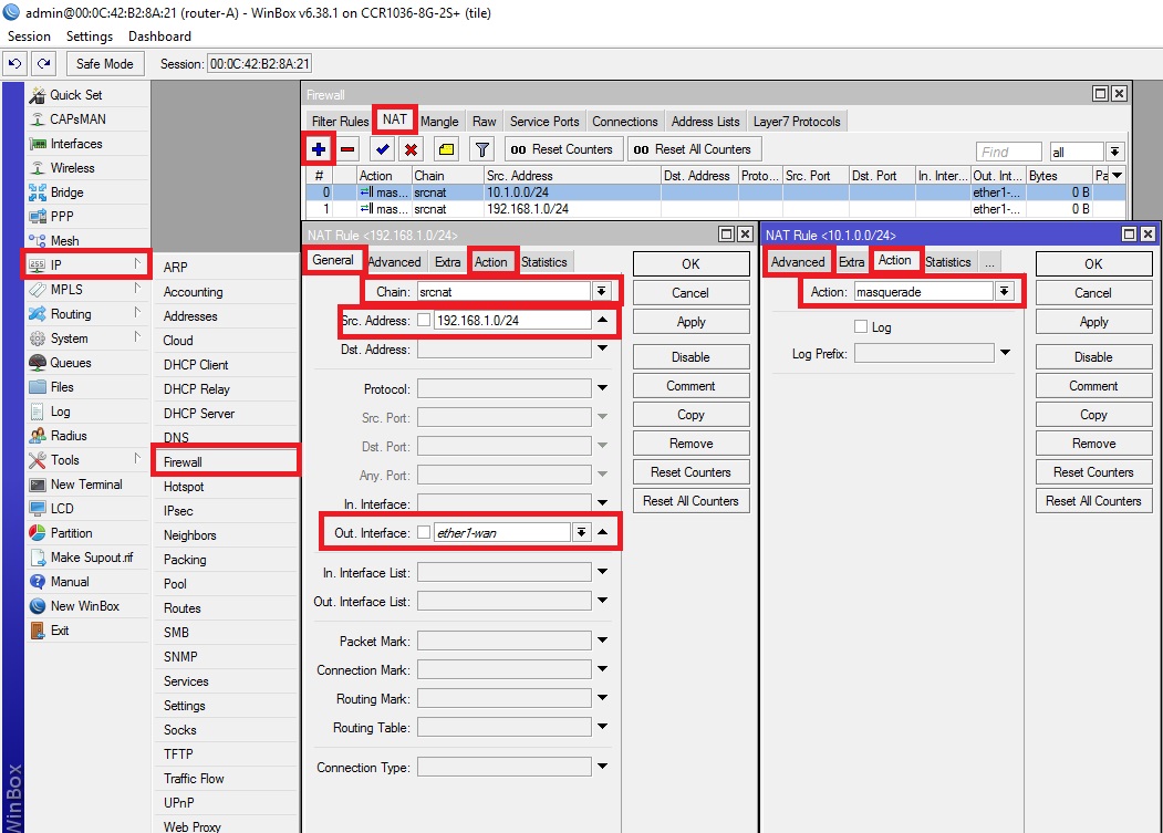
We enable NAT so that devices located on the networks 192.168.1.0/24 and 10.1.0.0/24 have Internet access.
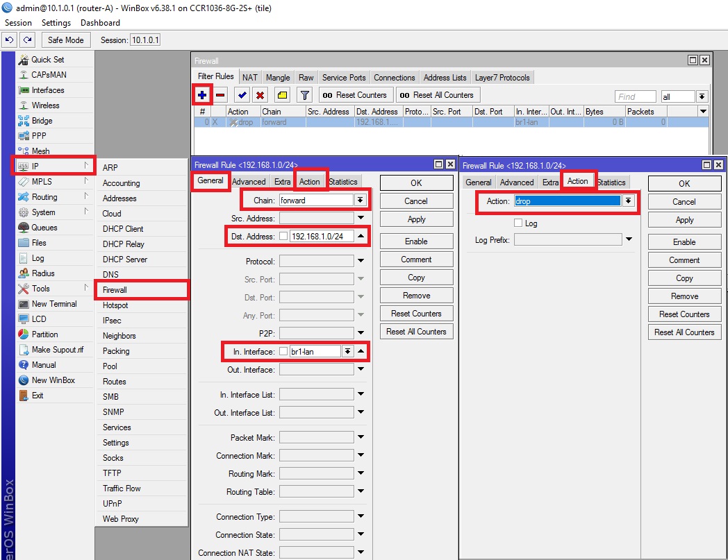
We isolate the subnets so that devices on the 192.168.1.0/24 network do not see or use devices on the 10.1.0.0/24 network. (I prefer to isolate this way; there is still a way to isolate subnets using Route Rules, but I will use the Firewall rule)
You can enable or disable this rule depending on your need for access to devices from the 10.1.0.0/24 network to 192.168.1.0/24 or vice versa.
Now configure the switching node B with the Mikrotik CRS125-24G-1S
switch. Let us call our switch “switch-B”:
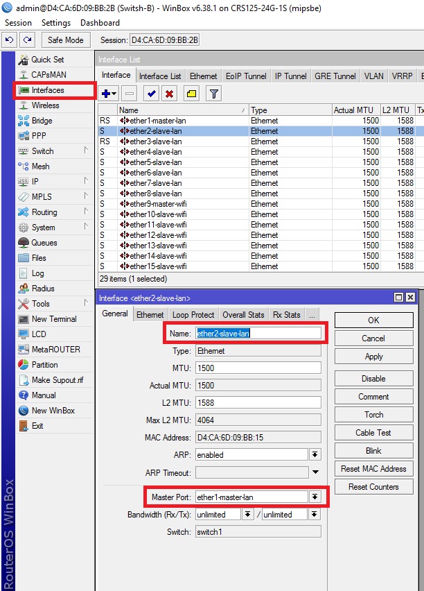
Denote the physical LAN ports. Combine ports 1 to 8, inclusive, into a common hardware switch with an ether-1 master port and denote it by master, the remaining 2 through 8 inclusive, denote slave. We will do the same with ports 9 through 16 inclusive with the ether-9 master port.
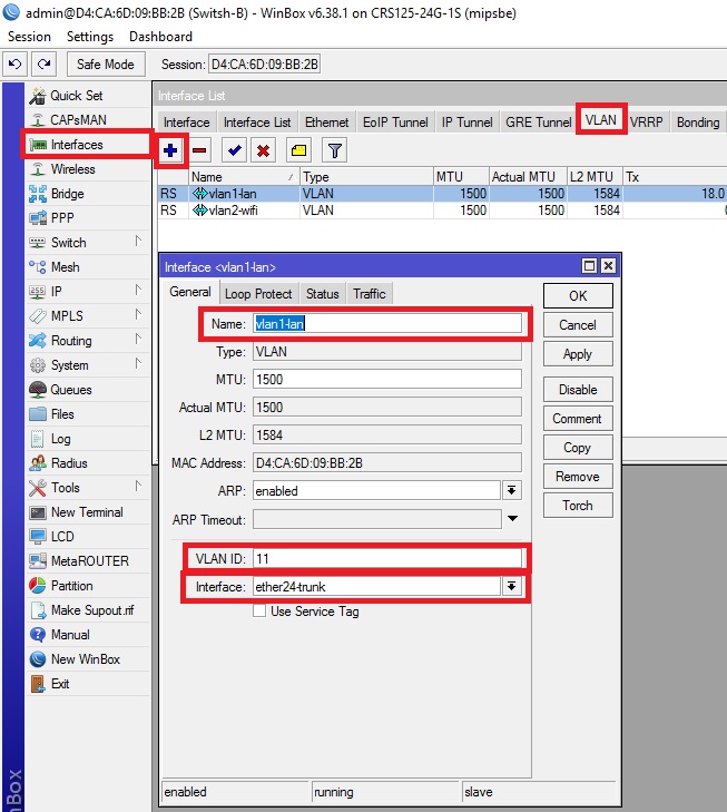
We create Vlan interfaces on the physical 24 lan port, with the help of which the networks 10.1.0.0/24 and 192.168.1.0/24 will be transported from switching node A via a trunk communication channel. Do not forget to specify the vlan id that we specified in accordance with the initial scheme.
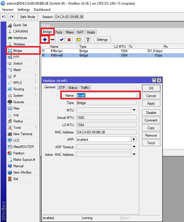
Create virtual interfaces in the bridge tab to combine the LAN ports.
Thus, we have a connection between switching nodes A and B, connected by a twisted pair cable, through which two different networks 10.1.0.0/24 and 192.168.1.0/24 pass through VLAN.
This option currently works in several hotels in Moscow and the Moscow region.
We set the conditional task so that on each switching node there is a class A network (10.1.0.0/24) for company employees and a class C network (192.168.1.0/24) for WiFi for visitors.
Suppose we have a switching node A with a Mikrotik CCR1036-8G-2S + router, a switching node B with a CRS125-24G-1S switch. Switching nodes A and B will be connected by a communication channel (Trunk) in our case over a twisted pair cable (there may be several communication channels (trunk) depending on the number of switching nodes; also if there is a fiber optic link and an SFP mikrotik optical module, you can assign trunk to SFP). Below is a twisted-pair trunk diagram.
Let's set up switching node A with the Mikrotik CCR1036-8G-2S + router.
Let's call our router “router-A”.
systemidentitysetname=router-AWe denote the physical ports so that there is no confusion about which networks they belong to. Let lan denote the physical ports that will belong to the network (class A) 10.1.0.0/24, wifi denote the physical ports that will belong to the network (class A) 192.168.1.0/24 and trunk the physical ports that will be used for the communication channel type trunk.
interface ethernet set [ find default-name=ether1 ] name=ether1-wan
interface ethernet set [ find default-name=ether2 ] name=ether2-lan
interface ethernet set [ find default-name=ether3 ] name=ether3-lan
interface ethernet set [ find default-name=ether4 ] name=ether4-lan
interface ethernet set [ find default-name=ether5 ] name=ether5-wifi
interface ethernet set [ find default-name=ether6 ] name=ether6-wifi
interface ethernet set [ find default-name=ether8 ] name=ether8-trunk
interface ethernet set [ find default-name=sfp-sfpplus1 ] disabled=yes
interface ethernet set [ find default-name=sfp-sfpplus2 ] disabled=yes
Create virtual interfaces in the bridge tab, to combine LAN ports.
interfacebridgeaddname=br1-lan
interfacebridgeaddname=br2-wifi
interfacebridgeaddname=br3-trunk
We create Vlan interfaces with the help of which the 10.1.0.0/24 and 192.168.1.0/24 networks will be transported to the switching node B via the trunk communication channel. VLAN id for network 10.1.0.0/24 will be 11 , and for network 192.168.1.0/24 it will be 22 . Using these id information will be transmitted on the traffic belonging to vlan1-lan and vlan2-wifi.
interface vlan add interface=br3-trunk name=vlan1-lan vlan-id=11interface vlan add interface=br3-trunk name=vlan2-wifi vlan-id=22Assign LAN ports of the router to virtual interfaces (bridge) according to the above scheme
interfacebridgeportaddbridge=br1-lan interface=ether2-lan
interfacebridgeportaddbridge=br1-lan interface=ether3-lan
interfacebridgeportaddbridge=br1-lan interface=ether4-lan
interfacebridgeportaddbridge=br2-wifi interface=ether5-wifi
interfacebridgeportaddbridge=br2-wifi interface=ether6-wifi
interfacebridgeportaddbridge=br3-trunk interface=ether8-trunk
interfacebridgeportaddbridge=br1-lan interface=vlan1-lan
interfacebridgeportaddbridge=br2-wifi interface=vlan2-wifi
interfacebridgeportaddbridge=br3-trunk interface=ether7
(I will add this LAN port for a possibly future switching node C, for every fireman)
Assigning Networks to Virtual Interfaces
ip address add address=10.1.0.1/24interface=br1-lan network=10.1.0.0
ip address add address=192.168.1.1/24interface=br2-wifi network=192.168.1.0
ip address add address=62.64.2.0/0interface=ether1-wan network=62.64.2.0
The provider provides me with the Internet protocol EOiP. Therefore, you do not pay attention to this command, but configure the Internet access via the wan port according to the settings provided by your provider
Set up a pool of distributed addresses for networks, set up dhcp
ip pool addname=pool-wifi ranges=192.168.1.50-192.168.1.220
ip pool addname=pool-lan ranges=10.1.0.50-10.1.0.220
ip dhcp-serveradd address-pool=pool-lan disabled=no interface=br1-lan name=dhcp-lan
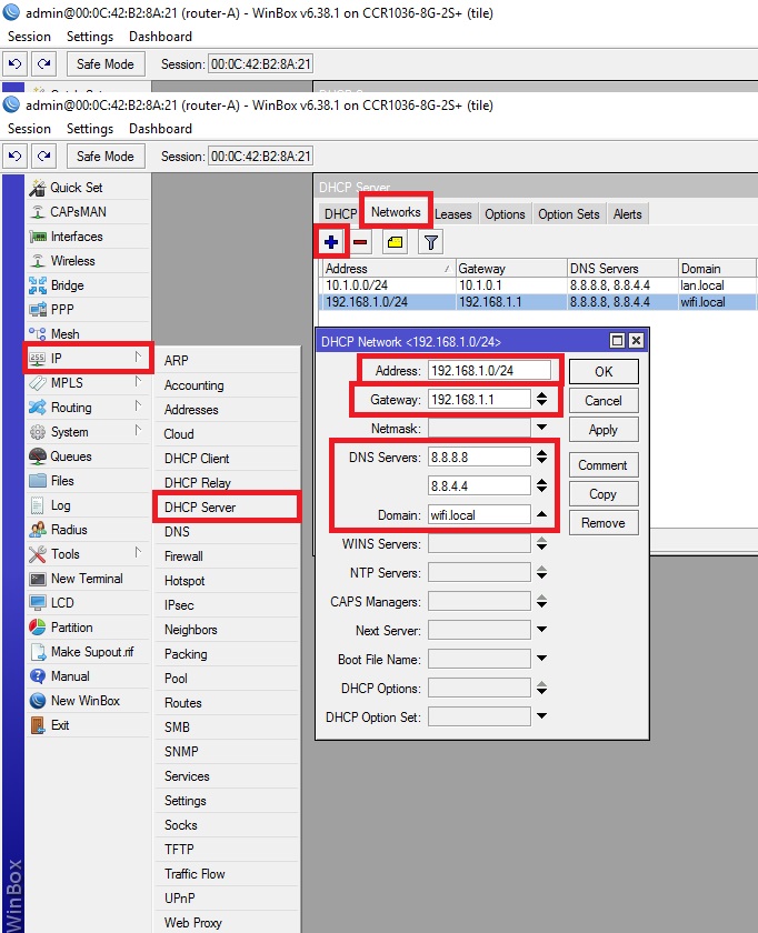
ip dhcp-serveradd address-pool=pool-wifi disabled=no interface=br2-wifi name=dhcp-wifiip dhcp-server network add address=10.1.0.0/24 dns-server=8.8.8.8,8.8.4.4domain=lan.local gateway=10.1.0.1
ip dhcp-server network add address=192.168.1.0/24 dns-server=8.8.8.8,8.8.4.4domain=wifi.local gateway=192.168.1.1We enable NAT so that devices located on the networks 192.168.1.0/24 and 10.1.0.0/24 have Internet access.
ip firewall nat add action=masquerade chain=srcnat out-interface=ether1-wan src-address=10.1.0.0/24
ip firewall nat add action=masquerade chain=srcnat out-interface=ether1-wan src-address=192.168.1.0/24
We isolate the subnets so that devices on the 192.168.1.0/24 network do not see or use devices on the 10.1.0.0/24 network. (I prefer to isolate this way; there is still a way to isolate subnets using Route Rules, but I will use the Firewall rule)
ip firewall filter add action=drop chain=forward disabled=yes dst-address=192.168.1.0/24in-interface=br1-lanYou can enable or disable this rule depending on your need for access to devices from the 10.1.0.0/24 network to 192.168.1.0/24 or vice versa.
Now configure the switching node B with the Mikrotik CRS125-24G-1S
switch. Let us call our switch “switch-B”:
systemidentitysetname=switch-BDenote the physical LAN ports. Combine ports 1 to 8, inclusive, into a common hardware switch with an ether-1 master port and denote it by master, the remaining 2 through 8 inclusive, denote slave. We will do the same with ports 9 through 16 inclusive with the ether-9 master port.
interface ethernet set [ find default-name=ether1 ] name=ether1-master-lan
interface ethernet set [ find default-name=ether2 ] master-port=ether1-master-lan name=ether2-slave-lan
interface ethernet set [ find default-name=ether3 ] master-port=ether1-master-lan name=ether3-slave-lan
interface ethernet set [ find default-name=ether4 ] master-port=ether1-master-lan name=ether4-slave-lan
interface ethernet set [ find default-name=ether5 ] master-port=ether1-master-lan name=ether5-slave-lan
interface ethernet set [ find default-name=ether6 ] master-port=ether1-master-lan name=ether6-slave-lan
interface ethernet set [ find default-name=ether7 ] master-port=ether1-master-lan name=ether7-slave-lan
interface ethernet set [ find default-name=ether8 ] master-port=ether1-master-lan name=ether8-slave-lan
interface ethernet set [ find default-name=ether9 ] name=ether9-master-wifi
interface ethernet set [ find default-name=ether10 ] master-port=ether9-master-wifi name=ether10-slave-wifi
interface ethernet set [ find default-name=ether11 ] master-port=ether9-master-wifi name=ether11-slave-wifi
interface ethernet set [ find default-name=ether12 ] master-port=ether9-master-wifi name=ether12-slave-wifi
interface ethernet set [ find default-name=ether13 ] master-port=ether9-master-wifi name=ether13-slave-wifi
interface ethernet set [ find default-name=ether14 ] master-port=ether9-master-wifi name=ether14-slave-wifi
interface ethernet set [ find default-name=ether15 ] master-port=ether9-master-wifi name=ether15-slave-wifi
interface ethernet set [ find default-name=ether16 ] master-port=ether9-master-wifi name=ether16-slave-wifi
interface ethernet set [ find default-name=ether24 ] name=ether24-trunk
We create Vlan interfaces on the physical 24 lan port, with the help of which the networks 10.1.0.0/24 and 192.168.1.0/24 will be transported from switching node A via a trunk communication channel. Do not forget to specify the vlan id that we specified in accordance with the initial scheme.
interface vlan add interface=ether24-trunk name=vlan1-lan vlan-id=11interface vlan add interface=ether24-trunk name=vlan2-wifi vlan-id=22Create virtual interfaces in the bridge tab to combine the LAN ports.
interfacebridgeaddname=br-lan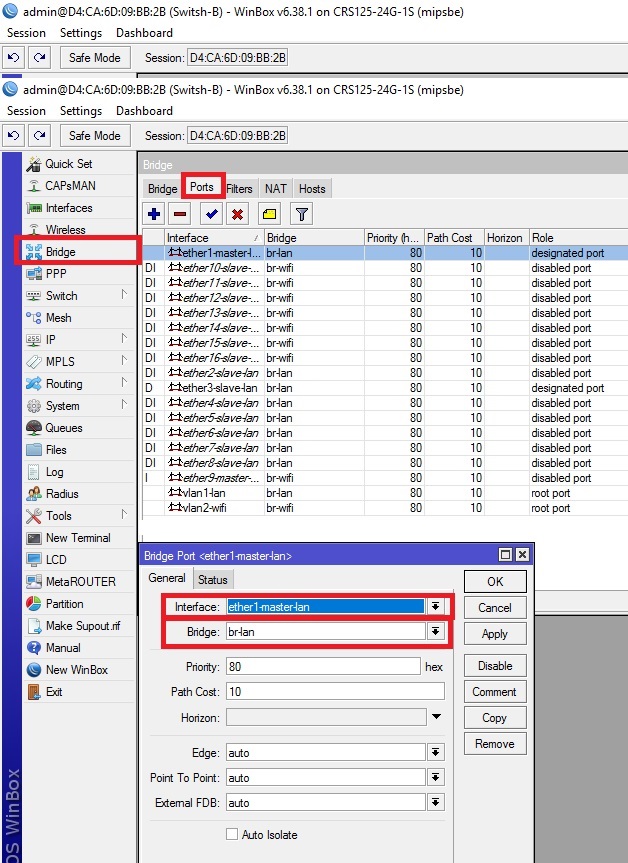
interfacebridgeaddname=br-wifiinterfacebridgeportaddbridge=br-lan interface=vlan1-lan
interfacebridgeportaddbridge=br-wifi interface=vlan2-wifi
interfacebridgeportaddbridge=br-lan interface=ether1-master-lan
interfacebridgeportaddbridge=br-wifi interface=ether9-master-wifiThus, we have a connection between switching nodes A and B, connected by a twisted pair cable, through which two different networks 10.1.0.0/24 and 192.168.1.0/24 pass through VLAN.