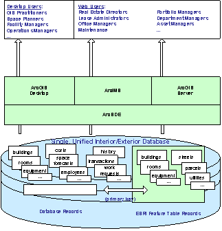
Translation of the ESRI Data Model Concept for Building Interior Space (BISDM)
This document contains background information and a description of the data model.
purpose
In October 2007, ESRI organized a discussion between representatives of standardization organizations, GIS users and software vendors to build a model of these facilities.
The resulting model means:
- To initiate projects in the field of premises management, allowing to achieve short-term organizational goals.
- To overcome real or imaginary barriers for connecting to GIS systems ERP (Enterprise Resource Management), IWMS (Integrated Workspace Management System), CAFM (Real Estate Infrastructure Management Automation System) and AEC (architecture, design and construction) applications.
- Carry out more holistic interaction between applications and reduce the number of transformations and data alterations. The model does this by highlighting the standard format and methods for storing drawings in the GIS, links to drawings within the GIS, or with drawings imported / exported to the GIS.
- Focus on getting practically useful results . That is, focus on all the elements of the model that provide immediate high returns and increase the utility of the application. It should be recognized that a unique advantage or secondary use of the model becomes possible only after its main elements are placed in their places; but the current stage of development of the model focuses on data that provides the basis for applications that in themselves justify the immediate adaptation of GIS to work with the premises.
- Be feasible . Represents a set of best practices for using facility data at the enterprise level. It focuses on the use of software and hardware technologies of today instead of using theoretically possible achievements of the future in the field of GIS technologies, processor or application performance.
- Lay the foundation for success by setting reasonable expectations for the use of GIS with rooms.
Beyond the boundaries of the model
In order not to lose concentration and avoid discussions that relate to the objectives of the room model, it is important to determine what the model is not going to do:
- Become a standard . There are existing well-developed standards for storing and exchanging data on real estate and A / E / C (architecture, design and construction) domains. This model is aimed at practical implementation instead of abstract classification. It reflects existing standards wherever possible. She will not duplicate or replace them.
- Be the only solution . This model represents one of the possible data structures suitable for practical use. It does not claim to be the only reasonable structure used to work in GIS with premises.
- Support all possible use cases . There are a large number of usage scenarios for GIS. This model focuses only on the main and widespread uses. Vertical applications, such as gas network tracking systems, which are truly GIS oriented applications, may find that they need their own specialized data elements.
- Support all GIS manufacturers . Although the principles of the model are based on generalized concepts, a specific model is expressed in terms of ESRIs and features.
- Stay static . Each organization has a unique mission or business model. Thus, each organization most likely has good reasons for expanding the model to represent the possibility of managing its own unique direction. Therefore, we should wait for the addition of the model.
- Become complete . The first draft phase of the data model will be completed in 2007, and the first pilot projects in February 2008. Usage scenarios that will not be implemented within this time frame will be carried over to the next phases.
- Say the last word . Software and hardware as well as standards are constantly being improved. Opportunities that were impractical this year will be possible next year. The model plans to be a catalyst for action, but not limited to change. But one thing is certain about the model - it will develop.
Guide
Technological processes and data for managing rooms are complex and often seemingly defy. However, there are several guidelines developed by various organizations that can be used to implement a successful application.
Applying a Service Oriented Approach
Most of the rationale for using space in a GIS is related to the creation of geographic data available for enterprise-wide deployment. Therefore, the model is structured in a way that allows you to integrate it into a typical enterprise stack. This topic deserves some insight because this approach simplifies the model, the speed of deployment, and makes it obvious that the model is positioned in large workflows in which GIS applications will run.
This approach is more important when processing room data in a GIS, rather than in other GIS applications. In most other GIS applications, such as hydrology, GIS systems themselves are the core of workflows. At the same time, building data on premises is most often carried out outside the GIS. Even when information is generated using geodetic methods in GIS, many of the consumers of information such as A / E / C consultants and suppliers require the delivery of information in such a way that it can be integrated into their own tools.
Faced with the similar requirements of workflows and information exchange, many IT organizations are moving to a service-oriented approach that can achieve the goal without replacing existing corporate applications, which will make it possible to avoid the need to centralize all data and processes, sharing information and logic along the natural boundaries of responsibility. A striking example of this practice in GIS conditions is the accounting function. It is not necessary to invent accounting functions of ERP (Enterprise Resource Management) systems within the GIS for their integration. The accounting functions and GIS practice only require the establishment of interfaces that will transmit data and tasks.
The same principles apply when working with data on real estate, architecture, maintenance and operation of buildings, or with data stored in IWMS (Integrated Workspace Management System) and CAFM (Real Estate Infrastructure Management Automation System). This data is already managed by systems with a long history, established standards and a strong industrial momentum - each of which GIS can try to reinforce instead of inventing again. To increase efficiency, even if GIS systems provide unique data, you only need to associate GIS with these systems.
For example, a maintenance management system will have complex schemes for tracking equipment, preventive procedures and steps, requests for work, work orders, information about the workforce and other aspects of the ongoing service. A GIS can add tremendous value to this business function by providing location information, managing the route, and creating the context for making equipment decisions. To provide these capabilities, the data model should only be connected to existing equipment information. The data model does not need to be imported or attempted to manage a complete array of equipment data.
This approach eliminates the need to overwrite existing standards, or duplicate data, or data models that are already sufficiently managed in BIM (Building Information Model), CAD (Computer Aided Design), ERP (Enterprise Resource Management), Real Estate Management System, IWMS ( Integrated Workspace Management System), CAFM (Real Estate Infrastructure Management Automation System), or CMMS (Computerized Maintenance Management System).
Using logical object identifiers
Ways of connecting systems to each other are in the spotlight of enterprises, because many elements of the data model need to use identifiers that are generated by systems external to the GIS.
Consider equipment that is often identified by a barcode received when it is received as part of an asset management program. This bar code identifies equipment throughout its entire life cycle and is used for various purposes: for easy management of movement and physical placement tasks, for solving maintenance tasks and for financial tasks such as tracking its cost and depreciation, as well as auditing.
Within this context, a GIS can provide tremendous added value when locating equipment across the entire enterprise, regardless of whether it is located inside or outside the building. However, for this data item - equipment - the GIS is only responsible for the location. Other data elements and the fact of the existence of equipment is controlled by other systems, and GIS applications must design their identifiers in accordance with the identifiers of external systems. Property, buildings, apartments and other elements follow the same pattern.
In these cases, primary keys are used that identify the elements, which ensures the best data connection. Combined with the fact that in many cases the additional information is external to the GIS, this structure often means that the spatial data of the GIS is stored in a set of tables, including logical identifiers (such as equipment barcodes) as a link or foreign key. The rest of the data is stored in separate tables in the external system (such as an asset management system) or imported from tables in the external system. In some circumstances, many foreign keys may be required for the connection between the spatial data of the GIS and the associated but independent external information system. This involves using a technique,
Defining a graphics source system
Objects with strong graphic connections are guided by other principles. For example, the identification of walls and doorways is generated from their graphical representation and location. No other representation, including value, exists without reference to graphic identity. In addition, the key properties of elements are their relationships with each other: such as the connection of walls to each other. In this case, connection to existing systems is possible only through mass import or export of whole parts of the model such as the floor or wing of a building.
Note that you cannot just use both approaches. You cannot establish correspondence between walls generated by GIS based on measurement data (external data), with walls generated in the BIM architectural model (internal data), without manual processing.
You cannot reliably re-import data about elements, such as walls, because unlike rooms or equipment, walls do not have a unique identifier that tells you which individual elements should be added, deleted or recreated.
Follow data-generating workflows
Because of these properties, the processes for graphics are one-way. You can repeat the import of building walls from the BIM (Building Information Model) model, but you must replace these walls in the GIS every time.
You can also re-import rooms from the BIM (Building Information Model) model, but all turning points for individual buildings, rooms or apartments must be recreated. You cannot sparingly correlate the data created in the BIM model (Building Information Model) and the data created in the GIS in the same place.
However, you can define different source systems for different areas. For example, you can establish that the graphical location of all objects located inside the building comes from the BIM (Building Information Model) model or from CAD. On the other hand, you can state that the location of all external equipment such as transformers or telephone poles comes from the data of geodetic measurements obtained inside GIS systems. There is no conflict in this, since only one source of information is installed for each piece of equipment. Again, this is only a recommendation, not a limitation.
As mentioned above, a room data model is only relevant within large workflows that generate or consume data. Make sure GIS data remains connected to live workflows, as this will ensure that the data is accurate, relevant and relevant to the enterprise.
Scalability
One of the key benefits of GIS is its ability to replicate and scale, so the model must consider scalability and performance issues. To this end, the data model is focused on the relational basis of GIS systems; that is, the room model is not an object-oriented project. This approach does not exclude the use of object-oriented methods, but assumes that the object-oriented code should be at the logical level or at the level of the application that processes the information, instead of the data level that stores the model.
In terms of describing standardized objects, relationships reflect compliance with the standard, but do not implement it. For example, in a room data model, walls will be mapped to elements inside the buildingSmart element(family of standards) IFCWall (wall); however, they will not implement the entire hierarchy of objects placed inside IFCWall .
Include only valid data
As long as it is not standardized which elements and attributes are included in the data model, there is only hope that the collection of information will provide a return on investment. This is especially true for the design stage of the collection, commissioning and processing of data, as the personnel designing the construction do not know what data will be used by followers and whether they will be stored.
All data incurs costs throughout the life cycle, whether they will be transformed, reviewed, or maintained. Even if you do a field survey, each additional attribute that you decide to collect in any case creates the cost of data entry, verification and import. In addition, any data cut off from the process that produces them becomes dangerously outdated and reduces the value of data that is accurate and reliable.
These considerations make it necessary to focus in the data model on a minimal set of elements that support short-term use cases, instead of a wide set of data that supports “foggy” goals. Such an approach, together with pragmatic workflows, is likely to accelerate practical implementation compared to a naive technique that demonstrates that it is impossible to reasonably provide consistent accuracy for the data that it claims to process.
Focusing only on enterprise-wide best practices
Avoid any recommendations that work well for demonstration purposes only, but do not scale for corporate use. For example, it is possible to include status assessment information in an equipment record. But in an enterprise, assessment tasks are tracked separately, as they can be performed repeatedly for each item of equipment, can be downloaded to the PDA and assigned to the master and subsequently can be transformed into a request for work. Therefore, the evaluation elements in the equipment table should be avoided.
Focus on GIS Guided Elements
Cases of use justifying the short-term implementation of GIS technologies for rooms are those that undoubtedly require amplification using properties unique to GIS.
These cases are those that:
- Require scaling;
- They require spatial connections;
- Collected using geodetic tools that are natural for geospatial environments;
- They require enumeration and analysis of enterprise-wide topological networks;
- They are justifiably an integral part of the overall operational picture of the building and its infrastructure.
Thus, the data model begins with GIS-directed content.
Relationship with Existing Standards
The data model in question intends to reference, rather than invent, existing standards for related fields.
buildingSmart IFC Model
http://www.iai-na.org/bsmart/
This standard is used by some members of the AEC industry (architecture, design, and construction) and standardizes geometric elements, connections, and constraints for building elements such as walls, doors, poles, and equipment. These elements in the model of these premises are internal elements of buildings and have a one-to-one mapping to elements of the IFC (Industry Foundation Classes) model.
The IFC (Industry Foundation Classes) model is designed for desktop systems, not for deployment in an enterprise environment. This model was also created without taking into account the fact that different pieces of data can be created by different groups within the enterprise. For example, equipment data is developed not only by an architect and engineer, but also by employees in finance, procurement, operation, and maintenance. Theoretically, they can be stored in one IFC (Industry Foundation Classes) facility. But in practice, these parts of the data are managed in various systems interconnected using web services, since information about depreciation, location and maintenance is more closely related to the owner-owned process, and not to other parts of the data.
CityGML
http://www.citygml.org/
CityGML belongs to a city-wide GIS. Mainly coincides with the model of premises when visualizing buildings. To this end, 3D buildings in the internal model are displayed on CityGML.
OSCRE
http://www.oscre.org/
This standard refers to the data of the building level real estate portfolio and refers internally to the standards of BOMA (Association of Property Owners and Managers), IFMA (Association of Professionals in the Operation and Maintenance of Real Estate), FICM ( Facilities Inventory and Classification Manual). Elements described by him are usually managed within the framework of IWMS (Integrated Workspace Management System) applications.
Corresponding elements within the GIS model of premises do not include elements related to OSCRE (Open Standards of the Real Estate Consortium) standards. For example, a GIS model of premises includes the location of a property in the form of a point feature with one attribute representing a unique real estate code (PROPERTY_ID). For example, code EO13327 is a unique identifier for a property used in an existing real estate registry. Thus, the internal GIS model stores the location, and the external system stores other properties and their hierarchies.
BOMA / IFMA / FICM / DIN277
http://www.boma.org/AboutBOMA/
http://www.ifma.org/
http://nces.ed.gov/pubs2006/2006160.pdf (FICM)
These standards regulate the classification of premises and, to a large extent, support the distribution of direct or indirect expenses aimed at generating income between divisions. For premises, these standards determine how the boundaries of apartments and rooms will be identified inside the BIM (Building Information Model) or CAD and how these spaces will be classified by equipment level and type. The model in question stores links to records external to the spatial GIS tables, and these external records are in IWMS (Integrated Workspace Management System) or CAFM (Real Estate Infrastructure Management Automation System), covered by these standards.
COBIE - Exchange of information on the design and operation of buildings
http://www7.nationalacademies.org/ffc/Bill_Brodt_NASA_COBIE_Oct_06_WP.pdf
http://www.bfrl.nist.gov/PSSIWG/presentations/COBIE1.pdf
This standard governs the operational procedures in work orders and service planning data in applications for work. The standard focuses on the exchange of elements such as warranties, service manuals, spare parts, special tools. The room data model under consideration refers to this information instead of including it. Thus, as long as the associated maintenance system complies with the COBIE standard, it is compatible with this model.
Integration methods
When analyzing real-world buildings, you cannot even express your opinion on the basic architectural concept of a building, not knowing how to implement its structure in concrete or steel. It is also hard to express your opinion about the data model without some idea of how to implement the applications built on it.
Web Services / Service Oriented Architecture
In this case, the application itself is responsible for transforming the initial data of the model into the application logic. The application is also responsible for coordination with the GIS.
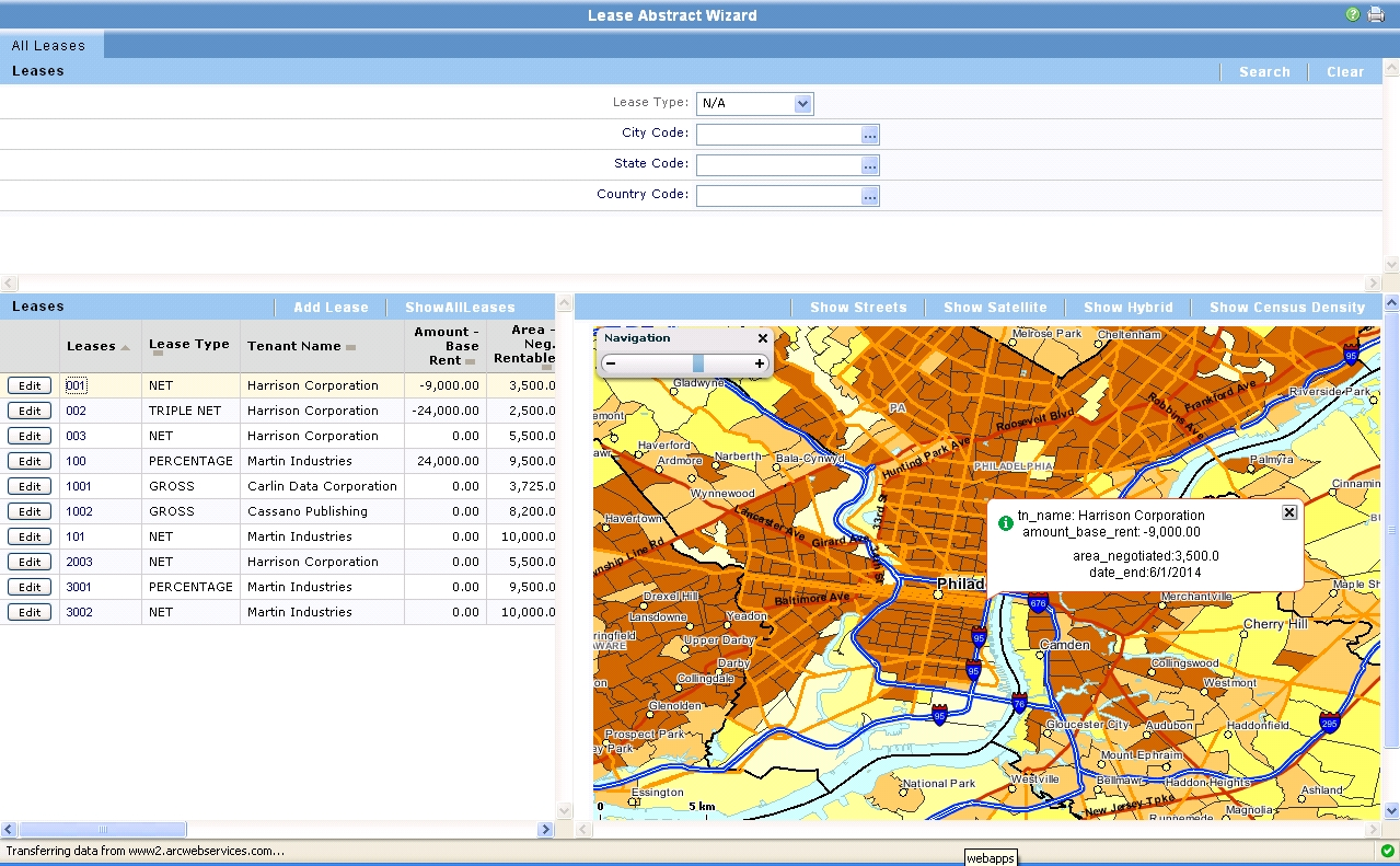
The figure shows an example of such an application. The model uses points (longitude and latitude) for buildings and uses this information for spatial reference of lease agreements concluded for premises in this building. The application uses web services to connect to the GIS and provides an up-to-date data display, in this case inventory data.
Direct database connection
In this case, the application data model and the room data model are connected at the database level. One way to do this is to use separate tablespaces within the same database instance and connect them using ArcSDE views. The first advantage of this approach is that application data and GIS can be queried as if they were part of one unified model. The second advantage is that these queries have very high performance. The third is that connections can be made using compound keys - an indispensable element for working with room data.
This design approach keeps geodatabases as specialized as possible and supports separate attribute assignment if this can be done better in a linked system containing workflows and associated relationships. The composite key problem illustrates some of the limitations of geodatabases in terms of application support, and this approach avoids these limitations completely.
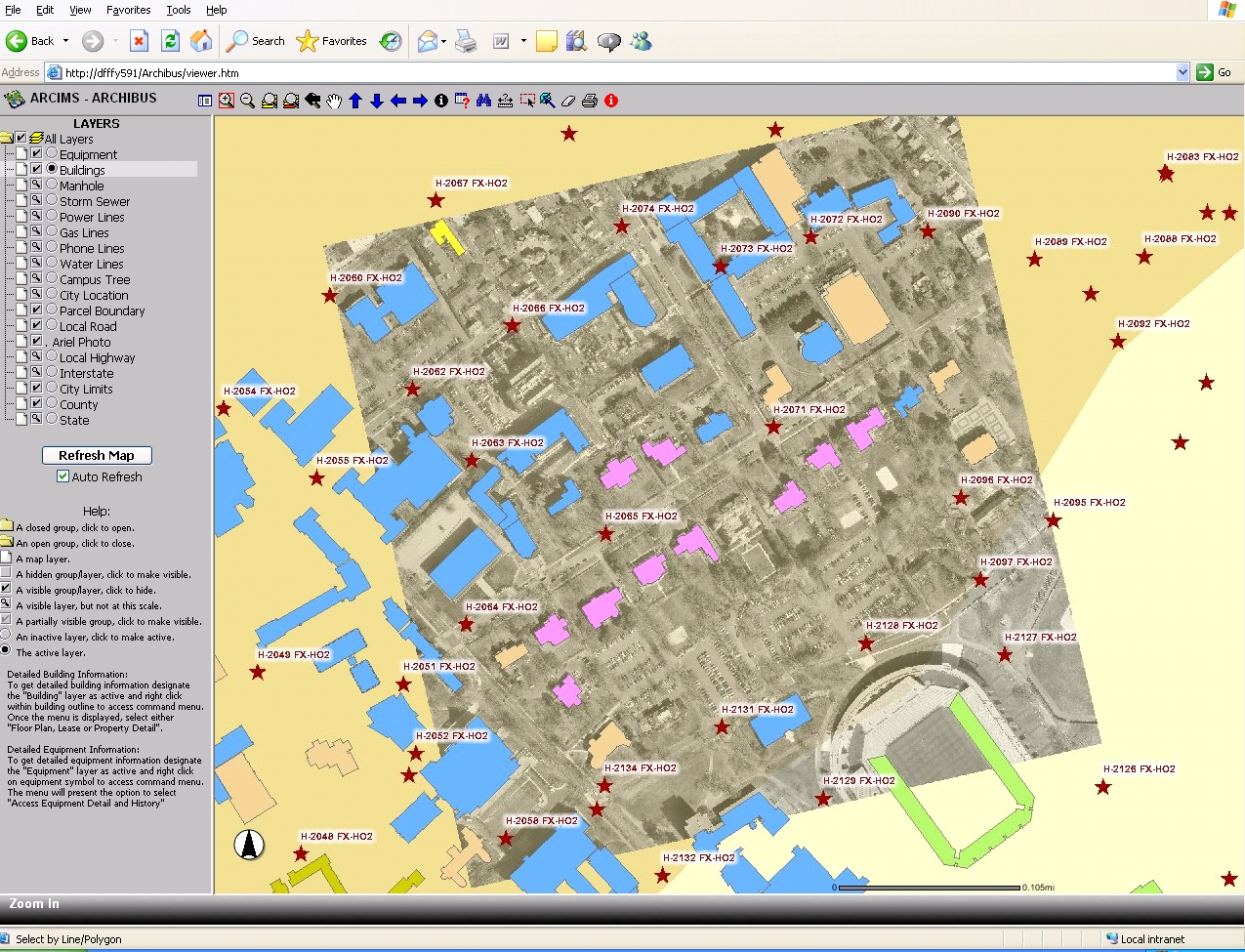
The figure shows an example of database integration. Data on roads, utilities and land comes from traditional GIS data sources. Data on buildings and their labels come from the property management application, and data and equipment labels come from the asset management application. However, data from all sources is available and displayed “seamlessly” in a GIS environment.
Database extension
When deploying some sites, enterprises will prefer to expand the model in question instead of integrating it with an external system. For example, instead of using a commercial asset management system to record equipment, they may prefer their own implementation using a new table in the geodatabase.
This can be done by following the above convention. For example, data on the spatial location of equipment identified by the equipment code may be in the same table. And the rest of the asset data will be placed in another table associated with the feature class. Despite the fact that this internal solution does not rely on any external system, it follows the best practices of data structuring, which facilitates their maintenance. For example, without losing data or their integrity, a GIS can create and delete spatial data, and an asset management system can create asset data. The only limitation is that when graphics are created, the GIS application must track the equipment code.
Import and export
Elements of the model of these rooms reflect, but do not implement or rethink existing standards. For example, applications can create data model elements from the BIM (Building Information Model) model or export them to the BIM model without additional losses typical of such data movements.
Nevertheless, the model of these premises is not going to become a standard, and therefore the export of elements to intermediate formats becomes optional. This approach allows the model to concentrate on creating a direct conversion of elements from key packages such as Revit ™, Bentley ™ or ArchiCAD ™ - practical and ready for production.
This approach also allows the model to strengthen the existing APIs of these packages in terms of managing key aspects of this migration and maintain broad compatibility with existing standards. For example, you can create walls using the Revit API simply by using the necessary materials, thickness and height of the elements. Revit can then export the model to buildingSmart IFC-compatible format. Alternatively, you can create elements in ESRI and use a data conversion program such as Safe Software's FME ™ to create an IFC (Industry Foundation Classes) compatible format. This approach satisfies all desirable use cases: you can quickly and efficiently convert data created in commercial software packages into a rich, vendor-independent format.
This approach also avoids any dependency on how the graphic data is stored. Data will be created in the environment that technological processes dictate, but it can go into any other environment that needs it.
Elements of the initial coverage of the model
This is a quick overview of the elements of this model developed in the initial phase.
In order to stay focused on immediate goals, this summary groups elements according to their use cases. Some elements, such as buildings, need different levels of spatial detail to support different use cases. In these cases, individual feature classes are described in general terms, since ESRI feature classes can include only 1 type of geometry (point, line, polygon, multi-point). Applications can use one or the other base class as needed.
Property Management
GIS elements store the geographic location of an element that is created, maintained, and deleted outside of spatial tables. For example, code EO13327 is a unique property identifier used in an existing property registry that contains data elements set by the Federal Real Property Council (United States Inter-Agency Council established to facilitate the efficient and efficient use of American real estate). Essentially, the GIS model of the premises stores the location, and external systems store other data on the property and their hierarchy.
Use cases
These elements are suitable for incorporating the spatial component in real estate and rental management applications, so that any property, lease or cost data can be linked and visualized with the buildings.
These elements do not cover the level of ownership of land, as land is well tracked in other models and standards (such as ESRI Parcels and Cadastre data model).
By combining property data with your real estate management system, you can quickly achieve the inclusion of a spatial component in it.
Feature Class Property
This table (actually a set of tables) contains graphical spatial data.
| Point feature class represents property location | |
PROP_ID | String | Unique identifier of the property. Property may consist of many buildings. |
 Property_Point
All other attributes will be stored in the source system and, as a rule, are not supported by GIS.
Property Information Table
While some sites will link to existing IWMS (Integrated Workspace Management System) or CAFM (Real Estate Infrastructure Management Automation System) systems, others will track property data items in their own tables. These tables contain data on property properties. A one-to-one relationship is established between entries in the spatial table “Property” and the table “Information about property”. Additional site-specific fields should be added to the “Property Information” table, and not to the “Property” spatial table.
You can also add a table with real estate, or the OSCRE table (Open Standards of the Real Estate Consortium), or any other table or service. But they should always be associated with the “Property” spatial table in the same way, namely, using a one-to-one relationship: the property has 1 entry in the “Property Information” table.
Any area is monitored by the building and its borders or the site and its borders. Buildings and plots are related properties.
| Property Information | |
PROP_ID | String | Unique identifier of the property. Property may consist of many buildings. |
PROP_NAME | String | Name of property |
DESCRIPTION | String | Property Description |
ADDRESS1 | String | Address bar 1 |
ADDRESS2 | String | Address bar 2 |
STREET | String | Street name |
CITY | String | City identifier or name |
STATE | String | Subject ID or USPS State Code |
ZIP | String | Postcode |
Zoning | String | Function Code |
BOOK_VALUE | Double | Book value |
MARKET_VALUE | Double | Market price |
 Property_Info
It is tempting to unify property addresses with other types of addresses located in the GIS. However, the addresses belong to the application that created them and, in this context, have a specific value for each application. A delivery agency has one definition for an address; a public safety application has another. Establishing a relationship between an address and property, as well as between an address and a building, is not a simple matter.
If the address should be connected with the cadastre or with the route building system, the addressing will be supported by a special technological process. The organization creates a structure that receives permission to issue addresses. The bottom line is a model in the form of points connected to the street network, so that you can perform route building. In the case of registered property, corporate users manually enter the address without following the formal process for determining it.
Columns with longitude-latitude coordinates.Buildings, depending on how they use the information, have more than one feature class associated with them. As an alternative way to store location data, you can add columns with longitude-latitude coordinates to the asset table. Property management systems will often set a location as an address rather than a point. Sites that want to use location information can use longitude and latitude to move to a specific location. This is a quick and effective way to display real estate on maps. It can also help with geocoding the location of a building from their addresses. As a result of adding this column, we get a method for determining the location of buildings and any of their contents in the broadest sense: lease agreements, tenants, equipment, etc.,
Building spatial data
Building information has two levels of geometric detail:
- points - used to analyze your portfolio on a city, region or state scale;
- areal objects - are used for planning at the enterprise territory level.
Each type of geometry has its own feature class, which can be linked to entries in the “Building Information” table.
Feature Class “Point Buildings”
| A point feature class represents the location of buildings. | |
PROP_BLDG_ID | String | Unique identifier combining property and building IDs |
Feature Class “Area Buildings”
| The polygon feature class represents the site below the building. | |
PROP_BLDG_ID | String | Unique identifier combining property and building IDs |
Any height assigned to the dimensions of the building is the conditional height used in planning the territory of the enterprise to visualize buildings relative to each other, instead of using the actual height used in landscape architecture. If the site needs the actual building height for landscape architecture, layout of architectural masses or zoning analysis, they probably need to model the buildings more accurately.
It is tempting to include information on the height of the building in the table, giving the opportunity for a rough layout of the architectural masses. However, just one value is not enough to satisfy expectations even from basic visualization. Full visualization involves a third view of buildings using multi-patches (ESRI spatial class for 3D visualization).
Building Information Table
This related table contains application information. An example of a table illustrating this relationship is given below.
| Building Details | |
PROP_ID | String | Unique identifier of the property. Property may consist of many buildings. |
BLDG_ID | String | The unique identifier of the building within the property. |
PROP_BLDG_ID | String | Unique identifier combining property and building IDs |
BLDG_NAME | String | The name of the building |
BLDG_USE | String | Building Use Code |
DATE_BUILT | Date | Build Date |
ADDRESS1 | String | Address bar 1 |
ADDRESS2 | String | Address bar 2 |
STREET | String | Street name |
CITY | String | City identifier or name |
STATE | String | Subject ID or USPS State Code |
ZIP | String | Postcode |
Building Interior Controls
Use cases
These items are suitable for:
- inclusion of georeferencing in IWMS (Integrated Workspace Management System), CAFM (Real Estate Infrastructure Management Automation System), asset management system and operational management system;
- basing the field collection of geo-referenced data on the environment, temperature or other useful data.
Floors and groups. Intermediary facilities, such as floors or groups for real estate or for the operational management of real estate, may be useful. In these cases, the “Floor” may simply be a confirmation code or graphic element.
| The table contains information about the floors of the building | |
PROP_BLDG_ID | String | Unique identifier combining property and building IDs |
FLR_ID | String | Floor id |
BLDG_FLR_ID | String | Unique identifier combining building and floor IDs |
Feature Class “Room”
| Полигоны, которые представляют контур определяющий помещение в соответствии с правилами группировки | |
BLDG_FLR_RM_ID | String | Уникальный идентификатор, комбинирующий ИД здания, этажа и комнаты |
CEILING_HEIGHT | Double | Высота потолка, как расстояние от пола, в футах |
ACTUAL_ELEVATION | Double | Фактически измеренная высота |
Like other elements, geometric properties are in a table with spatial data; assignment and functional group are in a related table. They can be implemented as a related view. Ceiling height is used for 3D visualization. This attribute is in the spatial table because this greatly simplifies the creation of a 3D object by extrusion. This attribute should be stored in each room, as some rooms on the same floor (such as a lecture hall, cafeteria) will have their own height.
Actual altitude is used for line of sight analysis and zoning studies.
Key geometric properties such as area can be calculated based on the geometric boundaries of the room.
Room Information Table
While some sites will link existing IWMS (Integrated Workspace Management System) or CAFM (Real Estate Infrastructure Management Automation System) systems, others will track basic room data within the geodatabase. This table contains information about the rooms. Additional site-specific fields should be added to this table, instead of a spatial table.
| Room Details | |
BLDG_FLR_ID | String | Unique identifier combining building and floor IDs |
RM_ID | String | Room id |
RM_NAME | String | Room Name |
BLDG_FLR_RM_ID | String | A unique identifier that combines the building, floor, and room IDs |
RM_CAT | String | Room Category Description |
RM_TYPE | String | Type of room |
DESCRIPTION | String | Description of “Room Information” |
DV_ID | String | Unit ID |
DP_ID | String | Department ID |
Using the fields of the room category and room type, sites can categorize the premises according to their standard methodologies (BOMA (Association of Property Owners and Managers), IFMA (Association of Professionals in the Operation and Maintenance of Real Estate), FICM (Facilities Inventory and Classification Manual), DIN277 (Platforms and building sizes)). Sites may wish to set acceptable values based on the selected standard.
The Zone feature class
 Building_zone Building_zone | A polygon feature class that represents part of a building. Zones may be associated with systems such as HVAC (heating, ventilation and air conditioning), security or other aspects of building management | |
BLDG_FLR_ZONE_ID | String | A unique identifier that combines the building, floor, and zone IDs |
| CEILING_HEIGHT | Double | Ceiling height, as the distance from the floor, in feet |
ACTUAL_ELEVATION | Double | Actually measured height |
Zones are a subset of floors that serve specific purposes, such as fire safety, life safety and security.
Zone Information Table
Zones are assigned by such systems as fire safety, HVAC (heating, ventilation and air conditioning), life safety, electricity, water supply, sewerage, fire fighting or building security system.
| Zone Details | |
BLDG_FLR_ID | String | Unique identifier combining building and floor IDs |
ZONE_ID | String | ID of the zone. Unique within the floor. |
BLDG_FLR_ZONE_ID | String | A unique identifier that combines the building, floor, and zone IDs |
DESCRIPTION | String | Description of “Zone Information” |
SYSTEM_ID | String | Идентификатор системы, которая может быть связана с зонами. Например может включать HVAC (отопление, вентиляция и кондиционирование), безопасность жизнедеятельности, электричество, охрану и т.д. |
Класс пространственных объектов “Оборудование”
| Класс пространственных объектов определяющий местоположение оборудования внутри здания | |
EQUIP_ID | String | Уникальный идентификатор оборудования |
Equipment can be positioned with a point object (for example, the latitude and longitude of the telephone pole on which the transformer is located).
The equipment communicates with the details using the equipment code, which you can think of as a bar code that individualizes it in an asset management and maintenance system.
It is difficult to find a use case that needs the actual height of the equipment instead of the conditional height.
Equipment Information Table
| Table “Information on equipment” information about equipment located inside the building | |
EQUIP_ID | String | Unique identifier of equipment |
EQUIP_STD | String | Equipment classification or standard description |
DESCRIPTION | String | Description of “Hardware Information” |
BLDG_FLR_RM_ID | String | A unique identifier that combines the building, floor, and room IDs |
The table “Information about the equipment” contains information on the purpose and functional group of the equipment. In most cases, this information will be located in an asset management system (for example, IWMS (Integrated Workspace Management System)) or maintenance system (CMMS).
The equipment table contains these items that will be cataloged for an inventory of assets or for maintenance. The equipment table does not contain other elements, such as elements of communication systems: panels, ports, connectors, network devices, and so on. They will need their own tables with unique attributes.
Internal modeling and analysis of buildings
Supported Uses
A set of elements allows you to:
- Collect information on the internal geometry of the building from geospatial surveys using automated robotic research;
- Collect environmental data;
- Analyze line of sight for security.
These data allow, but by themselves are not sufficient for:
- Analysis of the necessary information about the connectivity of network nodes for orientation or emergency evacuation.
In theory, exterior walls, windows and doors can be used for visualization, in the same way as in CityGML using LOD 2 (level of detail). In practice, this data is expensive to create or import into a highly structured form for visualization purposes only, and therefore this is not a priority for enterprise-wide data. Designers are looking for a way to visualize their buildings in the context of their surroundings, probably using the level of detail to the building, or special tools for the building of interest, instead of depending on the libraries that structure the building data available for these purposes.
The spatial classes of the interior elements of the building
All internal elements of buildings use the same linear feature classes to represent their boundaries as a collection of lines.
Walls, for example, consist of 5 lines, where the fifth represents the axis. Internal walls, external walls, columns, doors and windows - all will be subtypes of the same class.
3D display should use multipatches (ESRI spatial class for 3D visualization) to display the corresponding heights of the openings and shapes. This type of 3D representation is beyond the scope of this phase of the data model, with the exception of the representation typically created by extruding 2D features.
| Линейный пространственный класс, используемый для генерации полигонов внутреннего пространства. Линейные подтипы могут включать стены, окна, двери или административные границы | |
BLDG_FLR_ID | String | Уникальный идентификатор этажа. Уникален внутри здания |
BOUNDARY_SUBTYPEID | Integer | Поле подтипа базы геоданных для различения граничных объектов: стены, окна и т.д. |
NOTES | String | Заметки по границам |
SPACE_CATEGORY | String | Код категории классификации пространства |
CEILING_HEIGHT | Double | Высота потолка, как расстояние от пола, в футах |
BASE_ELEVATION | Double | Базовая высота здания или его части |
 Boundary_Line
Подтипы — BOUNDARY_SUBTYPEID | |
Boundary Line | Граничная линия |
Centrline | Ось |
Door | Дверь |
Exterior Door Line | Внешняя линия двери |
Exterior Wall Line | Внешняя линия стены |
Phantom | Искусственная линия |
Wall | Стена |
Window | Окно |
As mentioned above, internal geometric elements do not have a drilldown table associated with them.
Internal elements can be correlated with IFC's (Industry Foundation Classes). Relations between elements are discussed below.
Walls
Walls, lexical description:
http://www.iai-international.org/Model/documentation/IfcR2x_Final/IFCSHAREDBLDGELEMENTS/lexical/IfcWall.html
IFC (Industry Foundation Classes) geometry discussion:
http://www.blis-project.org /private/proposals/IFCR2_WallGeometry_991107_jh.pdf
Step-by-step directory:
http://www.steptools.com/support/stdev_docs/express/ifc2x3/html/t_ifcwall.html
Openings
Connection between walls and openings:
Doors
Doors, lexical description:
Window
Windows, lexical description:
http://www.iai-international.org/Model/R2x3_final/ifcsharedbldgelements/lexical/ifcwindow.htm
Conclusion
Future model coverage elements - real estate visualization
Use cases
This part of the model is suitable for:
- Visualization of the layout of the architectural masses for cities;
- View architectural context;
- Overview of the zoning regime: construction heights and visibility conditions.
Building visualization
For these purposes, buildings are created in the form of polymesh objects (multifaceted networks) with the display on their outer side of photographs showing their appearance. The same spatial object of the building is used, but only the applied layout elements of the architectural masses. These items are displayed on CityGML LOD 1 (level of detail).
This use case is consistent with the state of the art in terms of visualization. This view plays an important role in work processes where people try to understand the relationship between the artificial and the natural environment. The model development team will move on to this topic in later phases.
Data item | Type of | Appointment |
Building code | Alphanumeric | Contains a unique building identifier |
The layout of the architectural mass of the building | Polymesh (multifaceted networks) | Contains geometric data on the layout of the architectural mass of the building |
Фотографии внешней стороны здания | Растр | Содержит коллекцию совокупности внешних сторон здания |


Рисунки из gbXML.org
Будущие элементы охвата модели — другие функции
Случаи использования, подходящие для будущих фаз, включают:
- Ориентирование. Как только будет смоделировано внутреннее пространство и его элементы следующим высоко значимым шагом станет добавление внутренней маршрутной сети, информирующей и ориентирующей персонал, посетителей и ремонтников.
- План эвакуации. Сети внутреннего пространства могут также поддерживать планирование эвакуационных выходов и соблюдение зонирования при осуществлении деятельности.
Словарь узкоспециализированных терминов
BIM | Building Information Modeling | Информационная модель здания |
CAD | Computer Aided Design | Система автоматизированного проектирования |
CAFM | Computer Aided Facility Management | Система автоматизации управления инфраструктурой недвижимости |
CRE | Corporate Real Estate | Корпоративная недвижимость |
CMMS | Computerized Maintenance Management Systems | Компьютеризированная система управления техническим обслуживанием |
ERP | Enterprise Resource Planning | Управление ресурсами предприятия |
Feature | An object that has a geographic location or georeferenced shape stored as one of its properties. Features can be points, lines, polymeshes and other shapes | Пространственный объект — объект, который имеет географическое местоположение или геопривязанную геометрию, хранящуюся как один из его атрибутов. Пространственный объект может быть точкой, линией, Polymesh (многогранной сетью) и др. |
Feature Class | A set of features that have the same type of geographic representation and the same attributes | Many features that have the same type of geometry representation and the same attributes |
Gis | Graphical information system | GIS Geographic Information System |
Iwms | Integrated Workplace Management System | Integrated Workspace Management System |
Polymesh | A GIS feature used for representing complex 3D objects by tesselating the surface with triangular faces | Multifaceted networks. GIS spatial object used to represent complex 3D objects using tessellation (tiling, the automated process of adding new convex polygons to a polygonal mesh in order to increase the detail of the mesh) of the surface with triangular faces. |