Budget TrueRMS Measurement Option
- Tutorial
Introduction
Measurement of trueRMS AC voltage is not an easy task, not what it seems at first glance. First of all, because most often it is necessary to measure not a purely sinusoidal voltage, but something more complex, complicated by the presence of harmonics of noise.
Therefore, a temptingly simple solution with an average detector with recalculation in sr. values does not work where the waveform is very different from sinusoidal or simply unknown.
Professional voltmeters cf. sq. values are quite complex devices both in circuitry and in algorithms [1,2]. In most meters, which are auxiliary in nature and serve to control the functioning, such difficulties and accuracy are not required.
It is also required that the meter can be assembled on the simplest 8-bit microcontroller.
General principle of measurement.
Let there be some kind of alternating voltage of the type shown in fig. 1.
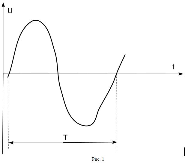
The quasi-sinusoidal voltage has a certain quasi-period T.
The advantage of measuring the rms voltage value is that in the general case the measurement time does not play a big role, it affects only the measurement frequency band. More time gives more averaging, less gives you the opportunity to see short-term changes.
The basic definition of cf. sq. values looks like this:
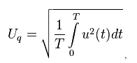
where u (t) is the instantaneous voltage value
T is the measurement period
Thus, the measurement time can be, generally speaking, any.
For real measurement with real equipment for calculating the integrand, it is necessary to quantize the signal with a certain frequency, obviously exceeding at least 10 times the frequency of the quasi-sinusoid. When measuring signals with frequencies within 20 kHz, this is not a problem even for 8-bit microcontrollers.
Another thing is that all standard controllers have unipolar power. Therefore, it is not possible to measure the instantaneous alternating voltage at the time of the negative half-wave.
In [3], a rather ingenious solution was proposed on how to introduce a constant component into the signal. However, in that decision the determination of the moment when it is worth starting or ending the process of calculating cf. sq. The values seem rather cumbersome.
In this paper, we propose a method of overcoming this drawback, as well as calculating the integral with greater accuracy, which reduces the number of sample points to a minimum.
Features of the analog meter
in Fig. 2 shows the core of the preliminary analog signal processing circuit.
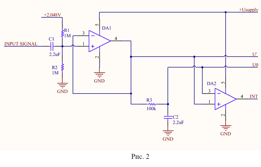
The signal is fed through a capacitor C1 to an amplifier-driver assembled on an operational amplifier DA1. The AC voltage signal is mixed at the non-inverting input of the amplifier with half the reference voltage, which is used in the ADC. The voltage selected is 2.048 V, since compact devices often use a supply voltage of +3.6 V or less. In other cases, it is convenient to use 4.048 V, as in [3].
From the output of the amplifier-former through the integrating chain R3-C2, the signal is fed to the ADC input, which serves to measure the constant component of the signal (U0). C of the driver amplifier, the signal U 'is the measured signal shifted by half the reference voltage. Thus, in order to obtain a variable component, it suffices to calculate the difference U'-U0.
The signal U0 is also used as a reference for the comparator DA2. When U 'passes through the value U0, the comparator generates a differential, which is used to form the interrupt procedure for collecting measurement samples.
It is important that in many modern microcontrollers both operational amplifiers and comparators are built in without mentioning the ADC.
The basic algorithm
in Fig. Figure 3 gives the basic algorithm for the case of measuring the magnitude of an alternating voltage with a fundamental frequency of 50 Hz.
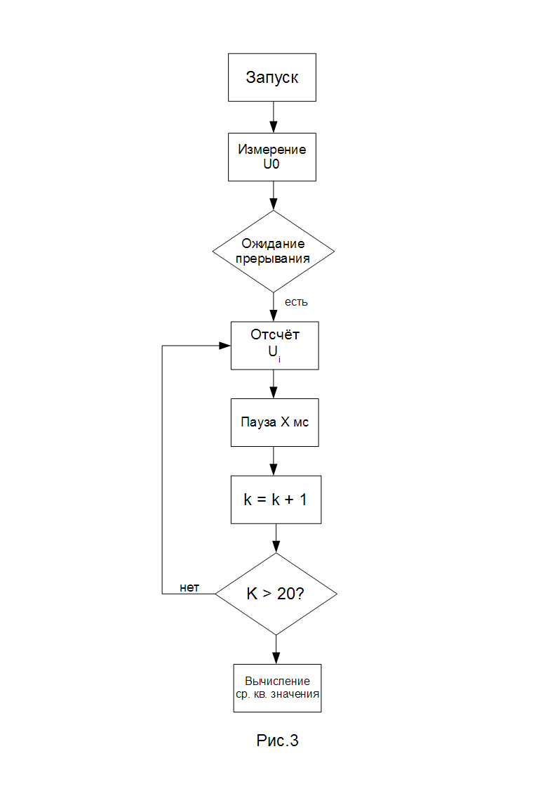
Measurement can be started by any external event up to a manually pressed button.
After start-up, the DC component in the ADC input signal is measured first, and then the controller switches to waiting for a positive difference at the output of the comparator. As soon as the differential interruption occurs, the controller makes a sampling of 20 points with a time step corresponding to 1/20 of the quasiperiod.
The algorithm says X ms, since the low-budget controller has its own delay time. In order for the measurement to take place at the right time, this delay must be taken into account. Therefore, the actual delay will be less than 1 ms.
In this example, the delay corresponds to measurements of quasi-sinusoids in the range of 50 Hz, but it can be any depending on the quasiperiod of the measured signal within the speed of a particular controller.
When measuring avg voltage values of an arbitrary quasiperiodic signal, if it is not known a priori what kind of signal it is, it is advisable to measure its period using the timer built in the controller and the same output of the comparator. And already on the basis of this measurement to establish a delay in sampling.
Calculation of the RMS value
After the ADC created the sample, we have an array of values U '[i], a total of 21 values, including the value U0. Now, if we apply the Simpson formula (more precisely, Cotes) for numerical integration, as the most accurate for this application, we get the following expression:
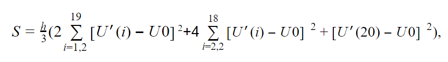
where h is the measurement step, and the zero component of the formula is absent, since it equals 0 by definition.
As a result of the calculation, we get the value of the integral in its pure form in the format of ADC samples. To translate into real values, the obtained value must be scaled taking into account the magnitude of the reference voltage and divided by the integration time interval.
where Uop is the ADC reference voltage.
If everything is counted in mV, K is approximately equal to 2. The scale factor refers to the differences in square brackets. After recounting and calculating S, we divide by the measurement interval. Given the factor h, we actually get division by an integer instead of multiplying by h, followed by division by the measurement time interval.
And in the final, we extract the square root.
And here the most interesting and difficult comes. You can, of course, use a floating point for calculations, since the C language allows this even for 8-bit controllers, and perform calculations directly using the above formulas. However, the calculation speed will drop significantly. You can also go beyond a very small RAM microcontroller.
To avoid this, you must, as correctly stated in [3], use a fixed point and operate with a maximum of 16-bit words.
The author managed to solve this problem and measure the voltage with an error of Uop / 1024, i.e. for the given example, with an accuracy of 2 mV with a total measuring range of ± 500 mV at a supply voltage of +3.3 V, which is sufficient for many tasks of monitoring processes.
The software trick is to do all the division processes, if possible, before the processes of multiplication or exponentiation, so that the intermediate result of operations does not exceed 65535 (or 32768 for operations with a sign).
A specific software solution is beyond the scope of this article.
Conclusion
This article discusses the features of measuring the rms voltage values using 8-bit microcontrollers, shows a variant of the circuit implementation and the main algorithm for obtaining quantization samples of a real quasi-sinusoidal signal.
References
Measurement of trueRMS AC voltage is not an easy task, not what it seems at first glance. First of all, because most often it is necessary to measure not a purely sinusoidal voltage, but something more complex, complicated by the presence of harmonics of noise.
Therefore, a temptingly simple solution with an average detector with recalculation in sr. values does not work where the waveform is very different from sinusoidal or simply unknown.
Professional voltmeters cf. sq. values are quite complex devices both in circuitry and in algorithms [1,2]. In most meters, which are auxiliary in nature and serve to control the functioning, such difficulties and accuracy are not required.
It is also required that the meter can be assembled on the simplest 8-bit microcontroller.
General principle of measurement.
Let there be some kind of alternating voltage of the type shown in fig. 1.
The quasi-sinusoidal voltage has a certain quasi-period T.
The advantage of measuring the rms voltage value is that in the general case the measurement time does not play a big role, it affects only the measurement frequency band. More time gives more averaging, less gives you the opportunity to see short-term changes.
The basic definition of cf. sq. values looks like this:
where u (t) is the instantaneous voltage value
T is the measurement period
Thus, the measurement time can be, generally speaking, any.
For real measurement with real equipment for calculating the integrand, it is necessary to quantize the signal with a certain frequency, obviously exceeding at least 10 times the frequency of the quasi-sinusoid. When measuring signals with frequencies within 20 kHz, this is not a problem even for 8-bit microcontrollers.
Another thing is that all standard controllers have unipolar power. Therefore, it is not possible to measure the instantaneous alternating voltage at the time of the negative half-wave.
In [3], a rather ingenious solution was proposed on how to introduce a constant component into the signal. However, in that decision the determination of the moment when it is worth starting or ending the process of calculating cf. sq. The values seem rather cumbersome.
In this paper, we propose a method of overcoming this drawback, as well as calculating the integral with greater accuracy, which reduces the number of sample points to a minimum.
Features of the analog meter
in Fig. 2 shows the core of the preliminary analog signal processing circuit.
The signal is fed through a capacitor C1 to an amplifier-driver assembled on an operational amplifier DA1. The AC voltage signal is mixed at the non-inverting input of the amplifier with half the reference voltage, which is used in the ADC. The voltage selected is 2.048 V, since compact devices often use a supply voltage of +3.6 V or less. In other cases, it is convenient to use 4.048 V, as in [3].
From the output of the amplifier-former through the integrating chain R3-C2, the signal is fed to the ADC input, which serves to measure the constant component of the signal (U0). C of the driver amplifier, the signal U 'is the measured signal shifted by half the reference voltage. Thus, in order to obtain a variable component, it suffices to calculate the difference U'-U0.
The signal U0 is also used as a reference for the comparator DA2. When U 'passes through the value U0, the comparator generates a differential, which is used to form the interrupt procedure for collecting measurement samples.
It is important that in many modern microcontrollers both operational amplifiers and comparators are built in without mentioning the ADC.
The basic algorithm
in Fig. Figure 3 gives the basic algorithm for the case of measuring the magnitude of an alternating voltage with a fundamental frequency of 50 Hz.
Measurement can be started by any external event up to a manually pressed button.
After start-up, the DC component in the ADC input signal is measured first, and then the controller switches to waiting for a positive difference at the output of the comparator. As soon as the differential interruption occurs, the controller makes a sampling of 20 points with a time step corresponding to 1/20 of the quasiperiod.
The algorithm says X ms, since the low-budget controller has its own delay time. In order for the measurement to take place at the right time, this delay must be taken into account. Therefore, the actual delay will be less than 1 ms.
In this example, the delay corresponds to measurements of quasi-sinusoids in the range of 50 Hz, but it can be any depending on the quasiperiod of the measured signal within the speed of a particular controller.
When measuring avg voltage values of an arbitrary quasiperiodic signal, if it is not known a priori what kind of signal it is, it is advisable to measure its period using the timer built in the controller and the same output of the comparator. And already on the basis of this measurement to establish a delay in sampling.
Calculation of the RMS value
After the ADC created the sample, we have an array of values U '[i], a total of 21 values, including the value U0. Now, if we apply the Simpson formula (more precisely, Cotes) for numerical integration, as the most accurate for this application, we get the following expression:
where h is the measurement step, and the zero component of the formula is absent, since it equals 0 by definition.
As a result of the calculation, we get the value of the integral in its pure form in the format of ADC samples. To translate into real values, the obtained value must be scaled taking into account the magnitude of the reference voltage and divided by the integration time interval.

where Uop is the ADC reference voltage.
If everything is counted in mV, K is approximately equal to 2. The scale factor refers to the differences in square brackets. After recounting and calculating S, we divide by the measurement interval. Given the factor h, we actually get division by an integer instead of multiplying by h, followed by division by the measurement time interval.
And in the final, we extract the square root.
And here the most interesting and difficult comes. You can, of course, use a floating point for calculations, since the C language allows this even for 8-bit controllers, and perform calculations directly using the above formulas. However, the calculation speed will drop significantly. You can also go beyond a very small RAM microcontroller.
To avoid this, you must, as correctly stated in [3], use a fixed point and operate with a maximum of 16-bit words.
The author managed to solve this problem and measure the voltage with an error of Uop / 1024, i.e. for the given example, with an accuracy of 2 mV with a total measuring range of ± 500 mV at a supply voltage of +3.3 V, which is sufficient for many tasks of monitoring processes.
The software trick is to do all the division processes, if possible, before the processes of multiplication or exponentiation, so that the intermediate result of operations does not exceed 65535 (or 32768 for operations with a sign).
A specific software solution is beyond the scope of this article.
Conclusion
This article discusses the features of measuring the rms voltage values using 8-bit microcontrollers, shows a variant of the circuit implementation and the main algorithm for obtaining quantization samples of a real quasi-sinusoidal signal.
References