January 31, 2017 at 22:52
Creating anamorphic distortion in Unity
Hello! Now I work in VRTech, and as part of the work, I came across an interesting problem that I want to talk about. The task was to obtain an anamorphic image display. I will try to tell what anamorphic distortions are, how to calculate the simplest case of a linear mapping of such distortion onto a plane, and I will also offer my solution implemented using Unity.
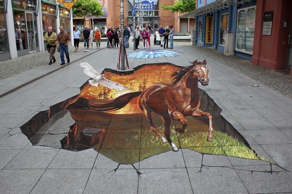
Recently at work I was offered an interesting task, to count on a leaflet how to transform a picture to create anamorphic distortion. I like math, for this reason I became interested, because I had never heard of them. What is anamorphic distortion?
In general, optical anamorphization is a way of image distortion, which implies a different scale of conversion in two mutually perpendicular directions. In general, it is used to remove promising distortions, but has also become a fairly popular tool in art.
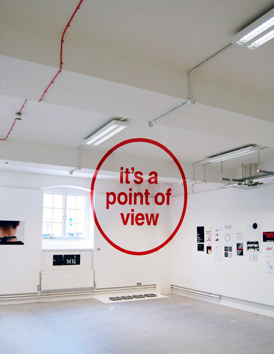
To create a credible effect, a point of view is a very important detail. If you saw 3D art on the street, then you understand that the step is right, the step is left and the illusion is breaking up.
After reading the articles on how such a conversion is done and realizing that there is nothing complicated in general, I, as a programmer, thought that there was probably a library ready for use somewhere on the Internet. Moreover, ideally, such a library should provide functionality to parametrically set the point of view, the estimated image height and other buns. I found a couple of solutions, but none of them worked. Therefore, I had to write my own.
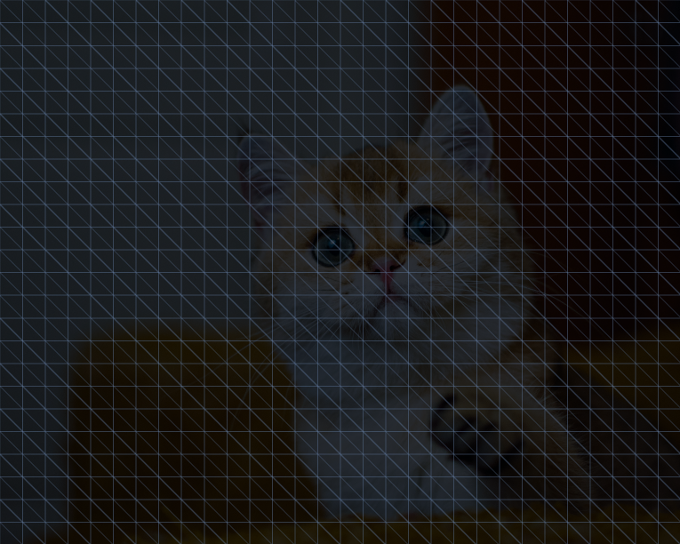
Let's go over how such an image is generally constructed. Initially, the desired result is taken and divided into a grid. The finer the grid, the more accurate the solution. In Unity, I decided to just generate a mesh where you can adjust the number of cells in the grid.
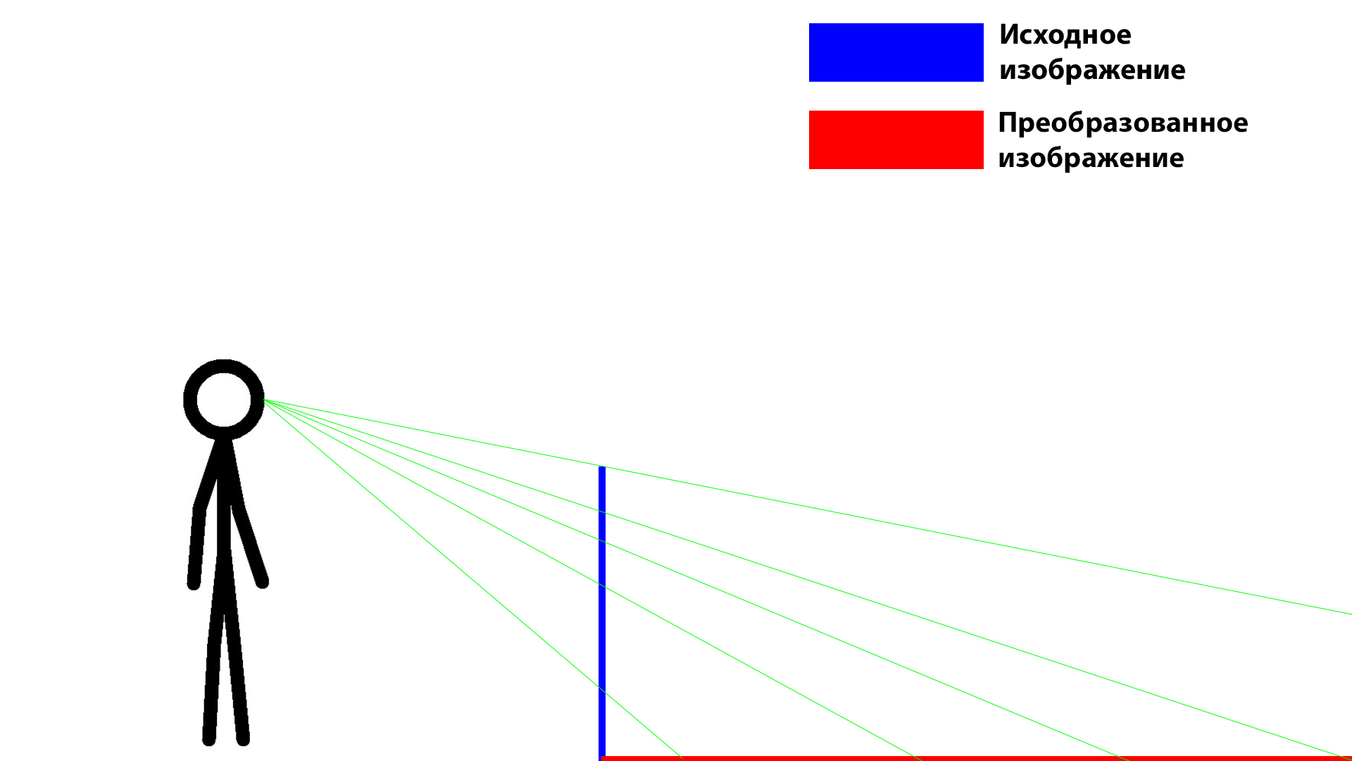
Next, select the viewpoint and the plane on which we will build our map. After that, in the flat case it’s trivial, we just draw the lines that go through the grid points and the viewpoint.
The choice fell on Unity, because I know it well, as well as all the articles that I found on the Internet were written in a popular, not mathematical, language, and I wanted to verify the correctness of the algorithm without unnecessary gestures (without printing a solution on the printer , and thinking what’s wrong here). In Unity, this is very simple to implement, since the result can be viewed through the camera in 3D space. In addition, there are implemented tools for working with 3D, vectors, etc.
According to the list of features, the solution was supposed to receive an image, the user's point of view, the height (in meters) of the result from the user's point of view, as well as the accuracy of the solution.
In order to make all this as simple as possible, I decided to make the easiest way to solve it. Generate the mesh correctly placing uv coordinates on it, pull the desired image on it. Next, use the projection to generate a new mesh with new vertexes and normals, but old uv coordinates.
The first task is solved quite simply, since the mesh has a simple structure, and it was necessary to generate a simple mesh and correctly number the triangles. The mesh in this case is the plane on which the whole picture is stretched, so the correct arrangement of uv coordinates is also not difficult.
You have already seen a cat for tests, but I will show it without “light”, so it is more beautiful.

The mesh was generated, then it was necessary to calculate new vertices and new normals. I decided to define new vertices by determining the point of intersection of a straight line drawn through two points and a plane defined by three points. The method of determining the intersection point between a plane and a straight line requires determining the normal to the plane, so the new normals were also calculated.
Everything, the solution is ready! In general, the task is quite simple, but at the same time interesting. I think on this effect you can even make a rather funny game and break the brains of the players. In the video you can see the result of the work. (The original image on the video is very dark, since I did not adjust the light)
A little later I can finish the functional so that it can be projected onto several planes, as well as onto reflective surfaces and achieve an effect like this.

Directly with the solution code, as well as to monitor its possible further development, can be here .
Recently at work I was offered an interesting task, to count on a leaflet how to transform a picture to create anamorphic distortion. I like math, for this reason I became interested, because I had never heard of them. What is anamorphic distortion?
In general, optical anamorphization is a way of image distortion, which implies a different scale of conversion in two mutually perpendicular directions. In general, it is used to remove promising distortions, but has also become a fairly popular tool in art.
To create a credible effect, a point of view is a very important detail. If you saw 3D art on the street, then you understand that the step is right, the step is left and the illusion is breaking up.
After reading the articles on how such a conversion is done and realizing that there is nothing complicated in general, I, as a programmer, thought that there was probably a library ready for use somewhere on the Internet. Moreover, ideally, such a library should provide functionality to parametrically set the point of view, the estimated image height and other buns. I found a couple of solutions, but none of them worked. Therefore, I had to write my own.
Let's go over how such an image is generally constructed. Initially, the desired result is taken and divided into a grid. The finer the grid, the more accurate the solution. In Unity, I decided to just generate a mesh where you can adjust the number of cells in the grid.
Next, select the viewpoint and the plane on which we will build our map. After that, in the flat case it’s trivial, we just draw the lines that go through the grid points and the viewpoint.
The choice fell on Unity, because I know it well, as well as all the articles that I found on the Internet were written in a popular, not mathematical, language, and I wanted to verify the correctness of the algorithm without unnecessary gestures (without printing a solution on the printer , and thinking what’s wrong here). In Unity, this is very simple to implement, since the result can be viewed through the camera in 3D space. In addition, there are implemented tools for working with 3D, vectors, etc.
According to the list of features, the solution was supposed to receive an image, the user's point of view, the height (in meters) of the result from the user's point of view, as well as the accuracy of the solution.
In order to make all this as simple as possible, I decided to make the easiest way to solve it. Generate the mesh correctly placing uv coordinates on it, pull the desired image on it. Next, use the projection to generate a new mesh with new vertexes and normals, but old uv coordinates.
The first task is solved quite simply, since the mesh has a simple structure, and it was necessary to generate a simple mesh and correctly number the triangles. The mesh in this case is the plane on which the whole picture is stretched, so the correct arrangement of uv coordinates is also not difficult.
You have already seen a cat for tests, but I will show it without “light”, so it is more beautiful.
The mesh was generated, then it was necessary to calculate new vertices and new normals. I decided to define new vertices by determining the point of intersection of a straight line drawn through two points and a plane defined by three points. The method of determining the intersection point between a plane and a straight line requires determining the normal to the plane, so the new normals were also calculated.
Spoiler heading
 private Vector3 GetIntersectionOfLineAndPlane(
        Vector3 linePoint1,
        Vector3 linePoint2,
        Vector3 planePoint1,
        Vector3 planePoint2,
        Vector3 planePoint3,
        ref Vector3 planeNormal)
    {
        Vector3 result = new Vector3();
        planeNormal = Vector3.Cross(planePoint2 - planePoint1, planePoint3 - planePoint1);
        planeNormal.Normalize();
        Debug.Log(planeNormal.ToString());
        var distance = Vector3.Dot(planeNormal, planePoint1 - linePoint1);
        var w = linePoint2 - linePoint1;
        var e = Vector3.Dot(planeNormal, w);
        if(e != 0)
        {
            result = new Vector3(
                linePoint1.x + w.x * distance / e,
                linePoint1.y + w.y * distance / e,
                linePoint1.z + w.z * distance / e);
        }
        else
        {
            result = Vector3.one * (-505);
        }
        return result;
    }
}
Everything, the solution is ready! In general, the task is quite simple, but at the same time interesting. I think on this effect you can even make a rather funny game and break the brains of the players. In the video you can see the result of the work. (The original image on the video is very dark, since I did not adjust the light)
A little later I can finish the functional so that it can be projected onto several planes, as well as onto reflective surfaces and achieve an effect like this.
Directly with the solution code, as well as to monitor its possible further development, can be here .