Hours on gas-discharge lamps (GRI), they are also Nixie clock
Project concept
The concept of this product is to meet the need to look at the real flame. Glowing discharge in gas is strictly speaking not quite a flame, although it looks like a real flame.
I like its color and it was the only motive to start creating such watches for myself in a single copy.
Tasks to create a device for mass production was not set.
Therefore, the project budget is noticeably more reasonable. Decisions were made on the basis of their own ideas about beauty, the cost of components was not taken into account. Of course, there are always restrictions and, for example, I didn’t buy large GRIs (gas-discharge indicators) of type IN18 - their price is more than an intuitively defined border and they did not fit into my concept of the product's appearance. I used the VOI type IN-12.
IN12 is filled with a mixture of neon (or a mixture of inert gases) and mercury vapor. Mercury vapors provide a significant increase in the durability of the device and give a bluish tint to the glow of the plasma. Other GRIs may contain no mercury and produce a clear neon glow.
The main function of the clock is to show the exact time (CEP, hello!). It is highly desirable that the time when turned on is set automatically and does not require any manipulations from the user. From my personal point of view, the buttons on such devices are not needed at all. Such devices with a dozen buttons and hundreds of functions caused by various combinations of keystrokes and keystroke times make me feel sadly. Firstly, GRIs are well adapted to display only numbers. Nothing else is provided for and attempts to display menu items and so forth. In my opinion - the use of an unusable tool. The same applies to additional functions such as an alarm clock, etc.
Secondly, it is obvious that it is impossible to remember what combination of keystrokes a particular function turns on. Writing programs for such devices is fun and enjoyable, but it’s impossible to use later.
This question is perfectly addressed in the book Donald A. Norman Design of familiar things. I will quote one passage:
“During the trips I used the Leitz slide projector several times. The first time was the most nightmarish. I began to lecture and showed the first slide. When it was necessary to move on to the next slide, the student in charge of the display gently pressed the button and with horror began to observe how the stand went in the opposite direction, slipped out of the overhead projector and fell from the table to the floor, mixing all the slides. In order to arrange the slides in order, it took 15 minutes. What happened was not the student's fault, but this elegant slide projector. How can one button perform two opposite functions? No one could have done everything right the first time. "
The problem was that one button performed two opposite functions - a short press would move the slide forward, a long button back."
Let's continue the discussion of setting the clock. Such devices are optimally configured from their own web page using a computer, tablet or smartphone.
The alarm clock for watches with GIR is not needed in my opinion - firstly, there are always cellular ones with such functions and a much more convenient interface. Secondly, the clock on the SRI cannot use an autonomous power source since the typical power consumption (200 Volts * 7 mA = 1400 mW or 1.4 watts) is quite large and goes beyond reasonable limits for chemical current sources. Consequently, the clock with the power source will be powered from the network, and the alarm function will be dependent on the reliability of the network.
From the above reasoning the following system emerges:
The clock on the network with power from the network, having the ability to take the exact time from the Internet, with the setting from your own web page. No additional features are required.
I nevertheless violated the strictness of this rule by adding the following features:
Hours can show outdoor temperature, humidity and atmospheric pressure. This function realizes my personal need for knowing the outdoor temperature when I get to work in the morning. I fasten my shirt every day in the same place and when the clock detects me there - they consistently show the outside temperature, humidity and air pressure in millimeters of mercury. The function turned out to be successful and highly demanded by both me and my family members. Data on outdoor temperature, pressure and humidity are taken automatically and remembered for the time between shipments from an external source. When the timeout is exceeded (data is outdated), the clock shows the current date. In my home system, data on the parameters of the environment are received at intervals of 10 minutes, the timeout "data is outdated" is set to 30 minutes. When designing the watch, it was assumed that an external command could be given by voice, for example, to say: “Watch, weather!”. However, when prototyping it turned out that this method is unreliable and inconvenient. Therefore, in the future, voice control was replaced by the method of determining the presence of a person in front of the clock according to the time-of-flight laser locator. The clock should show the weather data, if you stand in front of them for about a second.
Hours on an external command via the HTTP interface can display the data obtained in this command. The team transmits both the data itself and the time of their display on the display. It was conceived as an opportunity to display something from a computer on events, for example, overheating of the processor of a home server or some other parameters. Pledged interface allows you to display a seven-digit code from the outside, including two points. In practice, it does not apply at all.
Mandatory requirements also included the effect of a smooth change of numbers. This effect, the only one of all, I really like!
The brightness of the indicators should adjust to the ambient light, while maintaining the same image contrast.
The clock should display six digits and one auxiliary value in front of the digits to indicate exactly what is currently displayed.
Realization of the conceived, hardware solution
GRI selection
To display time and other data, four GRI IN-12A, two IN-12B and one IN-15A were applied.
IN-12B contain points that I used to separate hours-minutes-seconds.
GRI IN-15A can show a number of special signs “+”, “-“, “%”, “P”, etc., placed at the beginning of the line.
The optimal distance between the indicators.
To watch looked harmoniously, you should ensure a certain distance between the indicators, as between the letters in the line. The study of the question gave the following information: the optimal distance between the numbers 4 mm, between words 8 mm. The optimal distance between the numbers is provided with a tight fit of the indicators in the panels. I guess this is not by chance, the Soviet engineers thought with their heads when developing and made the right distance.
Synchronization with time servers
Consider ways to automatically get the exact time:
- Request over the Internet to the server exact time.
- Glonass \ GPS receiver. Unfortunately, in some cases it does not work: for example, in my apartment in the depth of the room the signal from the satellites disappears, an unsuccessful configuration of the surrounding buildings affects, in which the clear sky is visible only directly at the window.
- Cellular network. In theory, you can request time from a cellular station without registration (i.e., without a sim card). I have not tried. Theoretically, the most universal way that does not require anything from the user.
- Time signals on the long wavelength ranges. Difficult to use, no portable ready-made solutions.
In my opinion, the best way is to request the exact time via the Internet. It should be noted that the built-in functions for storing the current time of the ESP8266 turned out to be quite accurate: for a month of accidental disconnection of the network access point, through which the Internet was connected, including the hours described, the withdrawal was less than a minute. I determined this by the coincidence of the clock and computer time. After the power to the access point is restored, the time is automatically synchronized.
The choice of processor and control chips GRI
To control the clock requires a processor with the ability to go online. Of the available ones, these are boards based on ESP8266. The study showed that the board is cheap, distributed, has a rich ready-made software, created by enthusiasts, can be programmed in the Arduino environment.
Selection of the system
GEE is powered by a relatively high voltage of about 200 volts. According to the passport (see Fig. 1), IN12 requires at least 170 volts for the normal occurrence of a glow discharge at a current of up to 2 mA. The control system must be able to switch a current of several milliamps and withstand voltages in the region of 200 volts. In the Soviet Union, K155ID1 chips (133ID1, etc.) were manufactured (high-voltage binary decimal decoder). They worked perfectly in static mode, for one lamp 1 decoder was required. Now these microcircuits are available from old stocks and even are produced in small batches by the Integral plant in Minsk. In principle, a good choice for clocks on microcircuits-counters. However, they are difficult to use in the system on a microprocessor due to the limited number of outputs from microprocessors. So, the adopted ESP8266 watch has only a dozen conclusions, some of which have certain limitations. For 7 decoders, 28 pins are required, or an intermediate register to which data must be sequentially output and then issued in parallel to K155ID1, which dramatically complicates the circuit.
Fig 1. ID-12

glow-discharge indicator passport. Fig. 2. IN-15 glow-discharge indicator passport.
When using 155ID1 the effect of a smooth change of numbers requires a dynamic display. The fact is that GRI is a highly non-linear device and it is very difficult to control its brightness in an analog way by changing the voltage because of the high steepness of the characteristic current-applied voltage. In the low-brightness region, the gas discharge becomes unstable. Also, the external illumination affects the steady lamp on - as the external illumination decreases, both the breakdown voltage and the indicator on time increase. External photons serve as a kind of lighter, initiators of the discharge. By the way, the high steepness of the dependence of the current through the gas-discharge device on the applied voltage is used to obtain a stable voltage, in fact, such a gas-discharge device is a voltage stabilizer.
Dynamic indication when using 155ID1 + GREI is quite possible, but has several limitations. So, due to the peculiarities of the 155ID1 circuit design (relatively low-voltage key elements are only 60 volts), neighboring numbers and other undesirable effects are possible. These effects are struggling with a variety of tricks - both hardware and software. The RADIOKOT.RU website has a huge topic (https://radiokot.ru/forum/viewtopic.php?f=3&t=3210) dedicated to the NIXIE CLOCK, I read it all and made conclusions for myself - the dynamic display is not suitable for my purposes .
An Internet search gave an excellent 155ID1 substitute - this is the HV5622 chip, representing a 32-bit shift register with high-voltage outputs. The structural diagram is shown in Fig. 3.

Fig. 3. The structural diagram of the HV5622, Supertex inc. ©
HV5622 is capable of switching voltages up to 230 volts, receive data via a serial interface with a clock frequency of up to 8 MHz. Chips can be included in series in a chain. The control will require only 4 pins from the MC: data, a clock signal, a write signal to the output register and an enable signal. The only thing that caused some doubts was the supply voltage. According to the manual it should be at least 8 volts. And I would like to feed the chips from 5 volts, and even manage them with a logic signal with a level of 3.3v. In the internet I found a couple of examples of the use of such chips and power them from 5 volts. Therefore, when developing, I just in case provided an opportunity to install a 5622 power supply converter with higher voltage, but I did not immediately install these nodes. Practice has shown
Clock power
To power the clock on the GRI requires a power source with two outputs: 5 volts with a current in the region of semi-ampere and 180-200 volts with a current of about 10 mA. Standardly, the authors of such clocks solve the power issue as follows: an external switching power supply 220 -> 12 volts is used, of which 5 volts is made inside the clock, and 180 volts for powering the GII are obtained by a second pulse converter from the 12V input. Those. in fact, there are 2 pulse converters in the common power supply circuit, the first of which makes 220–12, and the second 12–180. In my opinion, it is inefficient. Therefore, I chose a very traditional way of using the finished TorAN15 toroidal transformer. The appearance of this transformer is shown in Fig. 4.

Fig. 4. TorAN15 transformer
I bought this transformer on the site ISTOK2.COM. The transformer has two secondary windings - one for 170 volts, the second for 6.3 volts. This made it possible to do the simplest power supply circuit. High to power the GRI is rectified by a diode bridge and filtered on capacitors. These parts are used from a waste fluorescent lamp. Low power supply for microcircuits is also rectified by a diode bridge, filtered on an electrolytic capacitor, and stabilized on an integrated stabilizer 7805. The efficiency of such a circuit is significantly higher than a system with two conversions, the reliability of the system is much higher. Plus a complete lack of high-frequency noise. Minus - unfashionable and heavy transformer. But the severity of the transformer in this case is rather a plus - I wanted the clock to be brutally massive.
So, the clock circuit is defined: it is a ready-made module based on ESP12E, three HV5622 chips, a light sensor based on MAX44009, and a traditional (I would even say conservative) power supply. Later, a person definition node was added in front of the clock on the basis of the VL53L0X time-of-flight distance measuring laser module. The circuit diagram of the clock is shown in Figure 5.

Figure 5. Dronsky Nixie clock. The electrical circuit
I divided the output switching as follows: the first three lamps - the first HV5622, the second three lamps - the second HV5622, the remaining HV5622 controls the lamp with special characters and dots in two IN12B.
At the design stage, it was unclear whether the SPI channel performance would be enough to output data for a smooth digit change. The fact that once a second to bring 96 bits is not difficult for ESP12E - no doubt. But is there enough speed to display the effects? According to calculations should be enough with a margin. But as you know, it was smooth on paper ...
Therefore, at first it was planned to output data in three stages, to each microchip separately. Practical testing has shown that the SPI channel speed is sufficient with a huge margin for effects, even at a clock time of 4 MHz. Even the ability to double the speed was unclaimed. As a result, all the microcircuits are connected in a chain and the output of 96 bits is performed by one command. According to the calculations, the output time of 96 bits should be 24 μs. Fig. 6 shows the recording of the logical analyzer of the output of seven characters on the GRI. The total output time, taking into account the generation of the LE signal, is less than 30 μS.
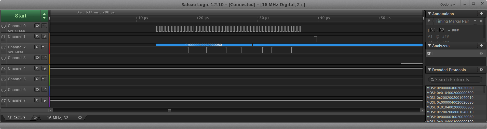
Figure 6. Record of the logical analyzer output 96 bit HSPI channel with a clock frequency of 4 MHz
Conclusions CLOCK all chips combined. The DI (Data Input) pins of the second and third microcircuits are connected to the DO (Data Out) pins of the first and second microcircuits, respectively. The LE (Latch enable) pins are combined, they are given a pulse, transferring data from the shift to the output register. Until the lamp is transferred, what is stored in the output register is displayed. The BLOCK pins are combined, connected to ground through a 1k resistor, to keep the output stages of the HV5622 in the off state before running the program in the MC. The manual recommends applying power, making the first data output and then switching on the output stages.
Brightness control
To control the brightness of the SRI, in order to maintain a constant optimal contrast of the indicators, the BLOCK pin is used, to which the PWM signal with a frequency of 2500 Hz is applied. A sufficiently high frequency of the PWM control signal was used, which ensured the absence of effects of the stroboscope, etc. In accordance with the norms (SNiP (Building Norms and Rules) 23 - 05 - 2010 (updated edition of SNiP 23 - 05 - 95) and Sanitary Rules and Norms SaNPiN 2.21 /2.1.1.1278-03) it is believed that a person does not perceive the frequency of pulsations of illumination above 300 Hz. In this case, the PWM frequency overrun almost an order of magnitude ensures an adequate level of visual comfort.
The effect of a smooth change of numbers
In order to get the visual effect of a smooth change of numbers, it is necessary to switch on alternately old and new numbers during the time of changing one digit to another (usually 200-250 mS), and the burning time of the old digit should decrease and the new digit should increase. The algorithm for changing numbers (subroutine change ()) performs 60 cycles. When you start the digit change algorithm, the first digit is enabled 100% of the cycle time, and the second 0%. As the cycles progress, the turn-on time of the first digit decreases from 100% to 0%, and the turn-on time of the second digit increases from 0% to 100%. Thus, the algorithm of smooth change of numbers for 200 ms and 60 cycles reduces the brightness of the first digit to the extinction, and the second to the full brightness.
The rest of the time interval of the second digit is switched on continuously and statically, their overall brightness is reduced by controlling the total on / off indication of the PWM signal on the BL terminals.
Figure 7 shows the signals recorded by the logic analyzer when changing numbers. It can be seen that at the beginning of the replacement subroutine, the old digit is turned on for the maximum time, and the new one is the minimum and for the shift time (approximately 250 mS) the burning time of the old digit decreases to 0, and the new one increases to the maximum. Visually, this manifests itself as a gradual decrease in the brightness of the old digit while simultaneously “thawing” the new one.

Figure 7. Recording control signals with a smooth change of numbers. The
effect video is shown here.
and here
and here:
Synchronization with time servers
After studying the question on the Internet, I concluded that most of the authors of the programs themselves write (or use ready-made third-party) routines for the NTP protocol. I was somewhat surprised, because the espressif SDK mentions built-in functions for working with real time. The built-in functionality provides a request for time servers (up to three), time correction (according to my observations - a request to the time server passes every 4-6 hours), conversion of the value in the form of unix time into a human-readable form, correction in accordance with the specified time- zone.
From the features of using the built-in real-time function: zero is returned to the first and several subsequent time requests and the diagnostics “start rtc from the beginning” is issued.
Watch start algorithm
When the clock is turned on, the system is turned on in the client mode and an attempt is made to connect to the access point with the stored details.
ESP8266 remembers these details after a successful previous connection independently in the service memory. This is a feature implemented in the SDK. If this attachment fails, the next attempt is performed, but the name and password to the access point are read from the EEPROM. The EEPROM also stores the time zone (a number in the range of -12 - +12), which is later used to correctly convert time to a local format.
If this connection failed, then the operation mode changes to “access point” and the web page of the clock becomes available at the standard address 192.168.4.1 for any device connected to this access point. In my case, the name of the access point is ESP_D. From a smartphone, tablet or laptop you need to go to the device page, select an access point and enter a password. While the access point mode is on, the client mode is disabled. This is due to the peculiarities of the system behavior in the situation when the connection to the access point failed. The system will continuously repeat attempts to join, it will be occupied only with this and there will be practically no resources left for anything else. Outwardly, this will appear as an unpleasant inhibition of the interface. The appearance of the page is shown in Figure 8.

Figure 8. The appearance of the WEB interface of the clock and the command line showing the response to the ping command
. This page displays all the access points found. Access points are sorted by signal strength, the top line is the access point with the strongest signal and is most likely the closest (i.e. the one to which you want to join). You must enter the password, select the time zone and click OK. The system will turn on the “client” mode (simultaneously with the “access point”), try to join. If the connection succeeds, the parameters will be stored in the EEPROM. If the connection failed, a corresponding message will appear on the page and you can try again to enter the password, etc.
After successful entry into the network, the “access point” mode will be turned off and only “client” mode will remain, i.e. The clock page is available only from the internal network.
So that you can access the clock by name (in my case “esp”), the NBNS library is launched, providing a response using the NetBios protocol. The work of the library allows the clock to respond to commands like ping esp and you can simply access them by the name of esp
For reasons that are not clear to me, this wonderful library, which forms a response to a broadcast request of the type “at what address is“ name ”?” And allows you to forget about the dreary procedure of determining the device's IP address using internal data of the router (switch), is used very rarely. Almost all the devices described on the internet on the ESP8266 do not use this simple and convenient mechanism. Laziness should move progress - but in this case does not move.
Next, the main program loop starts, in which the following occurs:
- The current time is polled and when the seconds pass, a time display change starts.
- The sensor of the illumination is polled and the PWM signal duty ratio is adjusted, which controls the brightness of the clock. The purpose of the adjustment is to maintain the same contrast figures when changing the illumination in the room.
- Poll sensor VL53L0X. This sensor is a time-of-flight laser range finder capable of measuring distances to an object up to 2 meters.
Experiments have shown that 2 meters is in ideal conditions, when a sheet of white paper or aluminum foil with a reflection coefficient close to one is used as a reflector. For ordinary objects with non-ideal reflection coefficient (cloth, human skin, etc.), the distance of confident determination is slightly more than 1 meter. If the sensor indicates the presence of an object in front of the clock, a subroutine will be launched to display the current outdoor temperature, humidity and air pressure. Measures were taken to increase noise immunity somewhat - the simplest algorithm “more than 50% of operations” is used. This means that over the 800 mS interval, the target should be detected at a distance of less than 1 meter in more than half of the range measurements. When debugging, the system showed that usually 50-60 operations occur when the target is in the field of view of the sensor.
The human detection system is triggered only when the target appears in sight. To once again run the show you need to step back and come up again. This is done to remove the situation that while you are standing in front of the clock all the time external parameters are shown.
The VL53L0X laser sensor uses an IR laser diode, which emits at a wavelength of 940 nm and is eye safe.
The video shows the reaction of the system to the appearance of an obstacle in the field of view of a laser locator:
The initial plan for launching the display of external data consisted in the use of a voice command recognition chip. To do this, I used the WTK6900B02 chip (voice command recognizer), courtesy of Sound Technologies. According to the description, the chip should recognize a dozen sound commands and issue a binary code corresponding to the received command. An impulse from the microcircuit was brought to one of the conclusions of the ESP8266 and a hardware interrupt handler was attached to it. A hardware interrupt records the fact of recognition of a voice command. In the chip I received, a number of commands in English were pre-recorded. I trained hard in the "correct pronunciation" of commands, so that they are recognized. It turned out that one should speak not at all with Oxford pronunciation, but with a Chinese accent :)), loud enough.
Despite the considerable time spent, I was not able to achieve reliable recognition of voice commands. The best I've got is about 50% correct recognition. Therefore, I was forced to use a different mechanism for triggering the display of external data - the VL53L0X laser distance meter.
In the main program of hours there are traces of using the voice control system.
Also in the program there are parts intended for reading the data of their UV sensor VEML6070. The fact is that I debugged the clock program alternately at home and at work, and I had only one MAX44009 sensor. Therefore, at work, the VEML6070 UV sensor was connected to the ESP8266 and a part of the program was written that determined which of the sensors was currently connected. To work out the contrast adjustment algorithm, this turned out to be quite enough, and I did not change anything in the final version of the program.
Data output in registers HV5622
As I mentioned above, control of gas-discharge lamps requires microcircuits capable of switching a sufficiently high voltage. I chose the HV5622 chips, which are a 32-bit register with sequential write and parallel read. The cathodes of the lamps are each attached to their own HV5622 output. For the ignition of a specific digit, it is necessary to output 0. To the first two HV5622, the cathodes of six GRIs are attached, to the third HV5622 - separator hours-minutes and minutes-seconds and cathodes of the seventh lamp with special characters. To enable the necessary digits in the lamps, it is necessary to output a 32-bit number to the register in which the log 1 (the data inside the HV5622 is inverted) corresponds to the desired cathodes of the lamps. The program contains arrays of 10 32-bit variables. Each element of such an array contains a binary number with log 1 at one of the positions, the output of which in the register will lead to the ignition of the desired digit. Since each microcircuit manages several GDIs, for output, it is required to preliminarily form one 32-bit variable from several elements, consisting mainly of logical 0, where the log 1 corresponds to the necessary numbers in each lamp.
It is worth mentioning that the decision to use arrays to control the GDI cathodes has a serious advantage: if a solder was made when soldering harnesses from GDI panels to HV5622 panels and the GDI conclusions were mixed up, then to fix it, just change the constant in the program without re-soldering anything. A significant number and close arrangement of the HV5622 pins make soldering two adjacent wires a cumbersome operation.
To completely fill all three registers, it is required to output 3 32-bit variables (totally 96 bits). It is unreasonable to do this with a “foot kick” - too long, time consuming.
Fortunately, the ESP8266 incorporates a hardware mechanism (HSPI) for serial data exchange, and the SDK has functions for accessing this mechanism. With the launch of this mechanism had to suffer. The difficulty was that it was not clear where to put the 32-bit variables for output in HSPI mode. To deal with the HSPI mechanism, I used a logic analyzer. After a series of experiments, I realized that 96 bits are output, but this is a necessary 32-bit number at the beginning and two 32-bit numbers containing arbitrary garbage. Search in the internet did not give anything, but at what point I realized that if there is an instruction of the form WRITE_PERI_REG (SPI_W0 (HSPI), d0); then you can try to write WRITE_PERI_REG (SPI_W1 (HSPI), d1); and further WRITE_PERI_REG (SPI_W2 (HSPI), d2); where d0, d1, d2 - 32-bit variables. Those. you must first decompose the data in registers SPI_W0 - SPI_W2, and then issue a command to start the exchange. I also note that the HSPI module can output up to 512 bits and there are only 16 such registers: W0 - W15.
The signal LE, in which data is moved to the output register HV5622, is generated programmatically.
System debugging
I did not dare to debug the system immediately with a full high voltage (230 volts) and made a dozen LEDs with a debug indicator with an operating voltage of 5 volts. After debugging, when I was convinced that the right LEDs were turning on correctly, the DDR were mounted in the panels and the high was sent. As a result of this sequence of debugging, not a single chip and not one indicator lamp suffered :). A photo of the node used for debugging is shown in Figure 9.
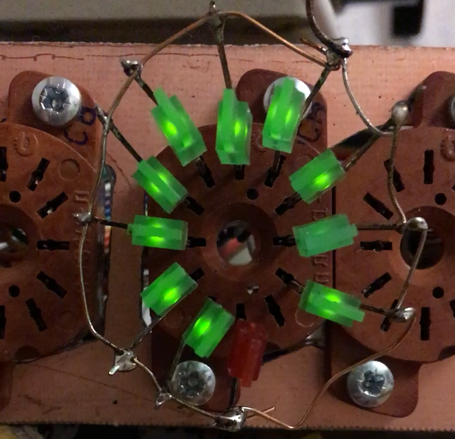
Figure 9. Photo of the debug LED node.
A short video of the debugging process here
Housing
The original idea was to make a brutal body made of thick metal such as copper, brass or bronze. However, since the Wi-Fi connection requires a dielectric body, only the thick metal front panel remains in the final version. A quick search on the Internet of firms performing custom-made cases gave a figure in the region of 5000 r per case. In my opinion, this is an unreasonable amount in the current circumstances. Therefore, I picked up the finished case (Gainta G2119C), bought it on the way to the dacha in the Shcherbinsky store of Chip-i-Deepa and stopped there, leaving the front panel and possibly another case for later.
Despite the flaw in the case of the watch, I decided to state the achieved results in the article, considering that the developed and applied circuit and software solutions would be of interest to society.
The exterior of the case today is presented in Figure 10.

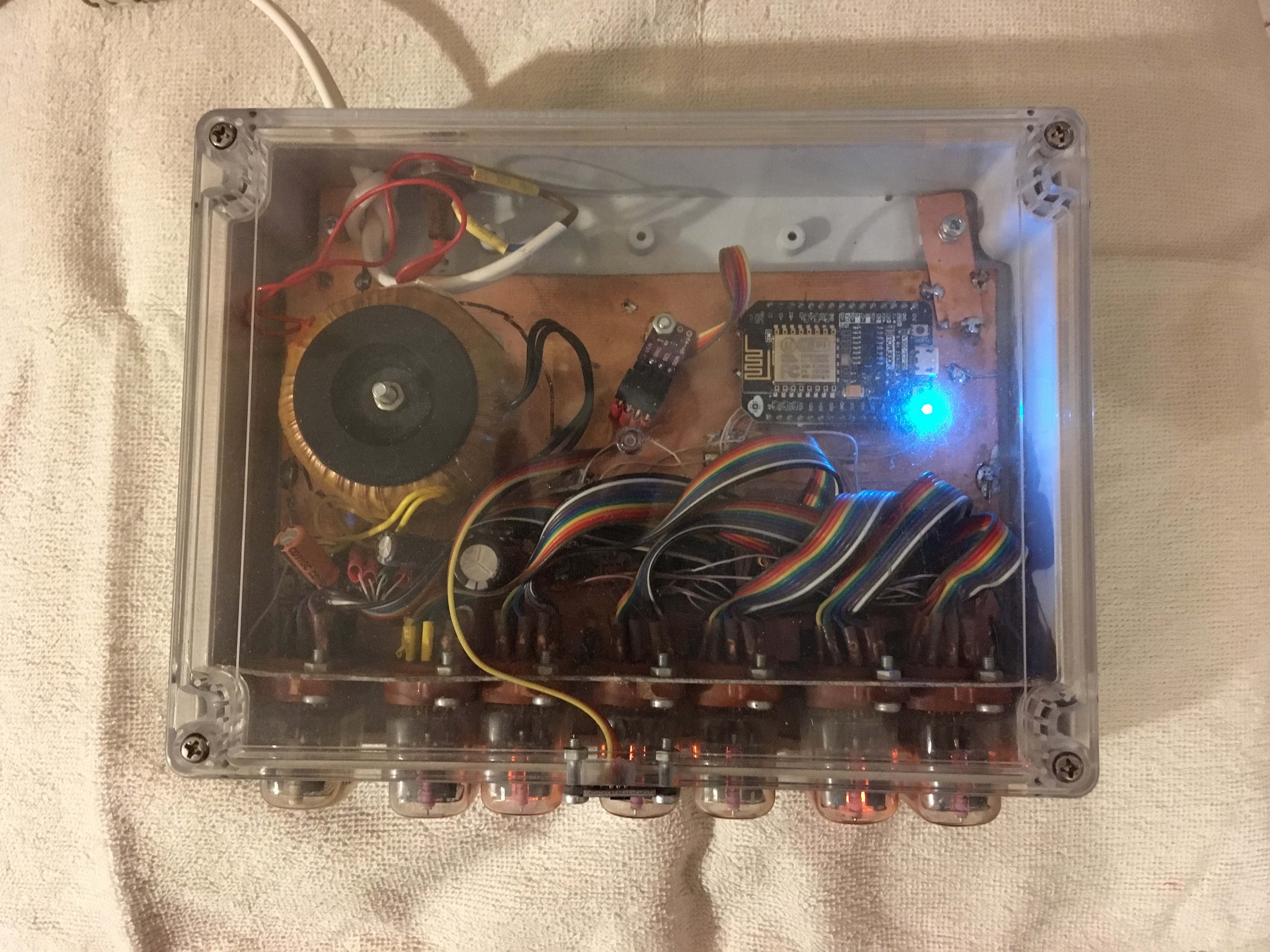
Figure 10. The appearance of the watch case
Conclusion
The clock has been working for more than a year, no glitches have been recorded, the tasks have been fully completed. Let me list again the distinctive features of my watch version:
- Static display mode with the simultaneous effect of a smooth change of numbers
- Using HV5622 ICs to control GDV
- Data in the HV5622 is recorded using the hardware HSPI mechanism
- The exact time is taken from the time servers from the Internet.
- Access to the clock is possible by name from the internal network
- Setup is required once at the first start.
- The complete absence of buttons, alarms, etc.
- Smooth adjustment of the brightness of the GDI with the aim of maintaining a constant image contrast within the specified limits of change in ambient light
- The clock reacts to the approach of the person and shows the street temperature, humidity, air pressure.
I am satisfied :)
→ Archive with the program is here