About the division of labor and its consequences
A few years ago we had the opportunity to take part in the development of a gas meter. At the time of starting work with the customer, he already had some best practices. And these developments seemed to us a very interesting example for demonstrating the consequences of an unsuccessful division of labor according to competencies. Under the cut, we will describe why the separation was unsuccessful, and how we solved the problems that arose as a result.
Three specialists took part in the development of the gas meter (in fact, more, but within the framework of the article we are only interested in three competencies). These were:
The designer provided a device that issued a signal for opening and closing a special valve. It looked something like this:
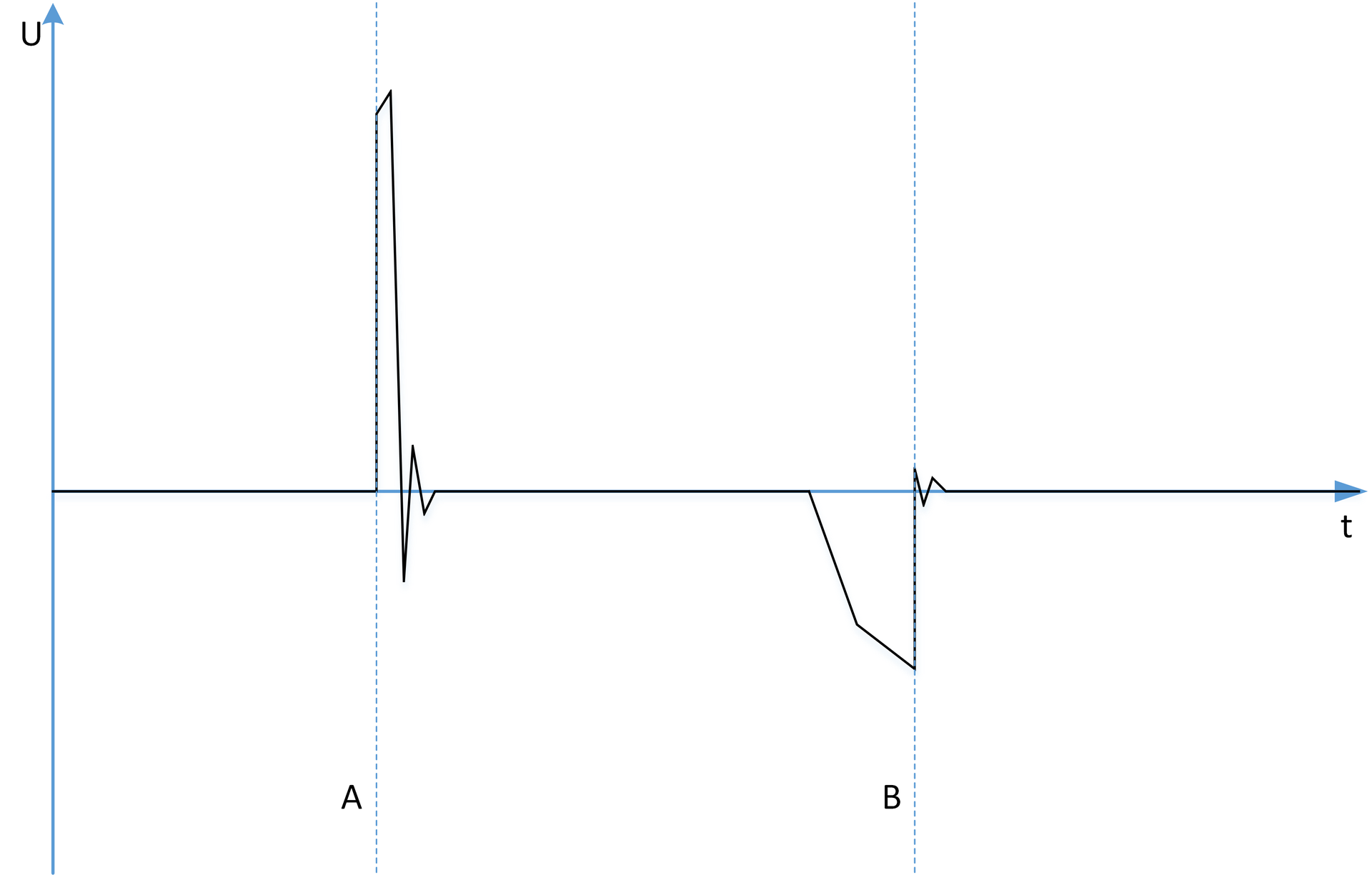
It was necessary to measure the time the valve was in the open state (distance from A to B), and the frequency of valve opening.
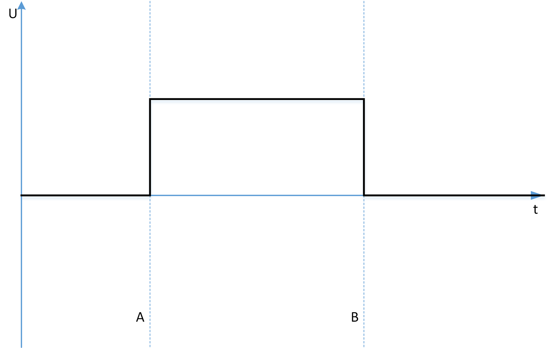
Of course, it is not possible to process such a signal directly with the microcontroller, so the circuit engineer was tasked with developing an intermediate converter that generates the following signal:
The device will operate on battery power, so most of the time the microcontroller will be in Sleep Mode. Therefore, the programmer asked to start the signal on the Interrupt pin, set the microcontroller to wake up by interrupting from the corresponding port, and in the interrupt handler started / stopped the timer.
Everything looks good so far, each specialist did his job and did it well. Only here, the quality of the device as a whole did not suit many people. At a constant flow rate, the device gave evidence with a significant dispersion and it was completely not clear what was the reason.
Incorrect operation of the flowmeter was discovered at an early stage of development. Such errors happen and there is nothing to worry about. Another thing is scary, no one knew where the error was and how to find it.
The reasons for the lack of accuracy of the flow meter could be:
In addition, the developers did not have full confidence that the problem occurs in principle, because the characteristics of the flowmeter were determined using a reference bench, which was developed in parallel with the flowmeter and was also far from ideal.
As a result, sooner or later we get a situation where each member of the team, being confident in the impeccability of the results of their work, crumbles a loaf on a neighbor. Whereas the higher management perceives the project as a whole and is dissatisfied with the whole team. Conflicts, high-profile disputes, separation arise in the team. The designer claims that there is an error in the program, the programmer says that there is an error in the design of the valve, etc.
The development of the flow meter was much more complicated and the customer decided to attract new specialists. So we set to work.
We saw two ways to solve the problem:
The first option looks pretty standard and very popular in the field of software development. For example, to check the software part, we buy or develop a precision generator of the signal generated at the output of the converter, feed it to the microcontroller and compare its readings under various conditions with the readings of the generator. The solution is not the cheapest and, sometimes, far from the fastest, but quite working.
The operability and quality of the input signal converter can also be assessed using a good and correctly tuned oscilloscope. Or develop a special device for conversion analysis.
But with checking the operation of the valve, everything is much more complicated, you need to apply a fixed flow rate, convert the valve signal and measure the signal using a specialized frequency meter. In fact, this is not much different from the flow meter that we already had.
Unfortunately, our customer was not ready to go this way, he needed a more elegant solution, especially since he could not develop a successful algorithm for checking the valve and signal generator.
Therefore, the customer was provided with an employee with competence in both circuitry and programming with metrology. His task was to analyze the situation as a whole and save the team from the opportunity to blame each other.
Take a look under the hood. And so our man-band started analyzing the project. The analysis began with an input signal converter: the

original circuit was not preserved, but its essence can be seen from the picture. As you can see, the circuit is built on a trigger (4013) and optocouplers. False positives are eliminated with the help of the Zener diode D1 and RC chains.
The circuit quite well converts the input signal from the valve. But when constructing it, the circuit designer did not take into account the final goal and the specifics of the signal.
The essence of the problem was that when setting the task to the circuitry, he was given an oscillogram of the input signal and the expected type of output. According to the oscillogram, the circuit designer could not see that the steepness of the key fronts A and B would be insufficient to ensure stable and timely triggering of the optocouplers. In fact, for the correct operation of the conversion circuit, the use of comparators was necessary. Such a solution was not very suitable for circuitry, because Comparators will complicate the circuit and will most likely produce greater consumption. In many respects, such a fear is connected with the habit of solving the assigned tasks exclusively in circuitry without cooperating with the programmer and without using the capabilities of the microcontroller.
Not everything went smoothly with the program either. On the one hand, if the microcontroller is awake all the time, it receives interruptions and instantly starts / stops the timer. However, once you turned on the energy-saving mode, how strange it began. Looking at the microcontroller's datasheet, we found that the wake-up time of the microcontroller depends on many factors and this significantly affected the accuracy of the measurements. The start and stop of the timer lagged significantly behind the input signal. The programmer knew that the wake-up time was comparable to the time the valve was in the open state, but he expected that it would only lead to a uniform shift in the start / stop time of the timer relative to the input signal. In fact, we received a significant scatter in the readings of energy-saving and awake microcontrollers. For the metrologist, this problem would be obvious, but he did not participate in software development, because did not have such expertise.
An analysis of the valve was not possible. It was difficult or impossible to test the valve and evaluate its operation without converting and measuring its signal. We decided to deal with problems in the converter and the program, get a measuring and computing unit that will not cause us doubts and test the valve using the resulting block.
Having understood the project as a whole, we set about solving obvious problems. The easiest way was to solve a software problem - starting and stopping the timer. The microcontroller that we used had a Gate-controlled timer that could start and stop in hardware until the microcontroller woke up and, if necessary, even without waking it up. If a programmer was interested in metrology, he himself would have found such a solution a long time ago and tried to implement it. But often programmers are only interested in programming. In addition, there were two more factors that significantly influenced the adoption of unsuccessful decisions by the programmer:
Along the way, we touched on the accuracy of the conversion of the input signal. For us, the need for a transition from optocouplers to comparators was obvious. The customer was worried about the problem of increasing consumption, he had already heard about it from his circuitry. The circuit designer was well versed in his subject area, but did not even think about the functionality of the microcontroller used on the project. Not only did the microcontroller already contain two comparators, but it also turned out that one of them would be enough for us, we will simply switch the lower and upper levels of the reference voltage programmatically, without the use of additional external switches. Considering that low power consumption was one of the key advantages of the microcontroller used by us, the comparator cost us very cheaply (about 8 μA). And the high input impedance of the comparator made it possible to make a fairly inexpensive set of reference voltages (not more than 10 μA). As a result, we have a pretty simple input signal processing scheme:

Because The signal comes from the valve, both positive and negative, we bias it using resistors R1 and R2. With the divider R3-R5 we set the reference voltages. As the voltage on the battery decreases, the reference voltages and the bias on R1 and R2 will decrease synchronously, so this will not affect the accuracy of the signal conversion.
To start and stop the timer due to the use of gate-control technology, our microcontroller generates gate opening and closing signals using a comparator at the hardware level without exiting sleep mode. RC chains have been canceled, since we can programmatically control the gates using the microcontroller's RA5 port. The comparator output is connected to the CLK trigger input. The reference voltage of the comparator is switched software (either C12IN0- or C12IN1- is connected, depending on whether we expect the valve to open or close).
By developing our own signal conversion circuit and our microcontroller firmware, we significantly improved the accuracy of measuring gas flow. We also helped the designer of the flowmeter. Now he could easily notice the flaws in the operation of the valve and the signal generator, and he did not have to think that the problem was not on his side. Even if he had questions, he had someone to discuss them with, because we could always describe the signal conversion and measurement algorithm from the point of view of metrology and, if necessary, correct something.
Separation of tasks by competencies allows team members to achieve a very high level of development in their fields, but sooner or later we will come to the conclusion that specialists cease to understand each other. In this situation, it is very useful to have at hand a person who is versed in all areas related to the project. It may not be as good as each specialist individually, but able to see the whole picture. Also, the experience of this project showed that such a specialist has a very positive effect on the interaction of specialists, cultivates the interest of engineers in working with each other. The programmer and circuit designer began to think more often about measurement errors, the circuit designer discovered new possibilities for using the peripherals of the microcontroller, the metrology designer began to trust his colleagues and actively use the results of their work to analyze the hardware.
I would also like to draw attention to the fact that having a superficial knowledge in a wide range of areas, a person-orchestra at the interview stage does not look attractive both from the point of view of a programmer, and from the point of view of a metrologist and circuit technician. But in fact, he can play a key role in a difficult situation.
Three specialists took part in the development of the gas meter (in fact, more, but within the framework of the article we are only interested in three competencies). These were:
- Design engineer, part-time specialist in metrology
- Circuit Technician
- Programmer
The designer provided a device that issued a signal for opening and closing a special valve. It looked something like this:
It was necessary to measure the time the valve was in the open state (distance from A to B), and the frequency of valve opening.
Of course, it is not possible to process such a signal directly with the microcontroller, so the circuit engineer was tasked with developing an intermediate converter that generates the following signal:
The device will operate on battery power, so most of the time the microcontroller will be in Sleep Mode. Therefore, the programmer asked to start the signal on the Interrupt pin, set the microcontroller to wake up by interrupting from the corresponding port, and in the interrupt handler started / stopped the timer.
Everything looks good so far, each specialist did his job and did it well. Only here, the quality of the device as a whole did not suit many people. At a constant flow rate, the device gave evidence with a significant dispersion and it was completely not clear what was the reason.
Why did this happen?
Incorrect operation of the flowmeter was discovered at an early stage of development. Such errors happen and there is nothing to worry about. Another thing is scary, no one knew where the error was and how to find it.
The reasons for the lack of accuracy of the flow meter could be:
- Errors in valve design and input signal generator
- Errors in the input signal conversion circuit
- Software bugs
In addition, the developers did not have full confidence that the problem occurs in principle, because the characteristics of the flowmeter were determined using a reference bench, which was developed in parallel with the flowmeter and was also far from ideal.
As a result, sooner or later we get a situation where each member of the team, being confident in the impeccability of the results of their work, crumbles a loaf on a neighbor. Whereas the higher management perceives the project as a whole and is dissatisfied with the whole team. Conflicts, high-profile disputes, separation arise in the team. The designer claims that there is an error in the program, the programmer says that there is an error in the design of the valve, etc.
What to do?
The development of the flow meter was much more complicated and the customer decided to attract new specialists. So we set to work.
We saw two ways to solve the problem:
- Total testing and acceptance of the work of each team member
- Man band
The first option looks pretty standard and very popular in the field of software development. For example, to check the software part, we buy or develop a precision generator of the signal generated at the output of the converter, feed it to the microcontroller and compare its readings under various conditions with the readings of the generator. The solution is not the cheapest and, sometimes, far from the fastest, but quite working.
The operability and quality of the input signal converter can also be assessed using a good and correctly tuned oscilloscope. Or develop a special device for conversion analysis.
But with checking the operation of the valve, everything is much more complicated, you need to apply a fixed flow rate, convert the valve signal and measure the signal using a specialized frequency meter. In fact, this is not much different from the flow meter that we already had.
Unfortunately, our customer was not ready to go this way, he needed a more elegant solution, especially since he could not develop a successful algorithm for checking the valve and signal generator.
Therefore, the customer was provided with an employee with competence in both circuitry and programming with metrology. His task was to analyze the situation as a whole and save the team from the opportunity to blame each other.
Take a look under the hood. And so our man-band started analyzing the project. The analysis began with an input signal converter: the
original circuit was not preserved, but its essence can be seen from the picture. As you can see, the circuit is built on a trigger (4013) and optocouplers. False positives are eliminated with the help of the Zener diode D1 and RC chains.
The circuit quite well converts the input signal from the valve. But when constructing it, the circuit designer did not take into account the final goal and the specifics of the signal.
The essence of the problem was that when setting the task to the circuitry, he was given an oscillogram of the input signal and the expected type of output. According to the oscillogram, the circuit designer could not see that the steepness of the key fronts A and B would be insufficient to ensure stable and timely triggering of the optocouplers. In fact, for the correct operation of the conversion circuit, the use of comparators was necessary. Such a solution was not very suitable for circuitry, because Comparators will complicate the circuit and will most likely produce greater consumption. In many respects, such a fear is connected with the habit of solving the assigned tasks exclusively in circuitry without cooperating with the programmer and without using the capabilities of the microcontroller.
Not everything went smoothly with the program either. On the one hand, if the microcontroller is awake all the time, it receives interruptions and instantly starts / stops the timer. However, once you turned on the energy-saving mode, how strange it began. Looking at the microcontroller's datasheet, we found that the wake-up time of the microcontroller depends on many factors and this significantly affected the accuracy of the measurements. The start and stop of the timer lagged significantly behind the input signal. The programmer knew that the wake-up time was comparable to the time the valve was in the open state, but he expected that it would only lead to a uniform shift in the start / stop time of the timer relative to the input signal. In fact, we received a significant scatter in the readings of energy-saving and awake microcontrollers. For the metrologist, this problem would be obvious, but he did not participate in software development, because did not have such expertise.
An analysis of the valve was not possible. It was difficult or impossible to test the valve and evaluate its operation without converting and measuring its signal. We decided to deal with problems in the converter and the program, get a measuring and computing unit that will not cause us doubts and test the valve using the resulting block.
Man band
Having understood the project as a whole, we set about solving obvious problems. The easiest way was to solve a software problem - starting and stopping the timer. The microcontroller that we used had a Gate-controlled timer that could start and stop in hardware until the microcontroller woke up and, if necessary, even without waking it up. If a programmer was interested in metrology, he himself would have found such a solution a long time ago and tried to implement it. But often programmers are only interested in programming. In addition, there were two more factors that significantly influenced the adoption of unsuccessful decisions by the programmer:
- The programmer did not work in active power saving mode. He simply did not encounter the problem of slow wake-up of the microcontroller and the effects manifested in connection with this
- The programmer has already worked with a Gate-controlled timer and is faced with the fact that it simply does not work. So on all subsequent projects, he avoided this function and was afraid of it like fire. As it turned out, not all programmers read Errata and track revisions of microcontrollers. In the early revisions of the microcontroller, this function really did not work.
Along the way, we touched on the accuracy of the conversion of the input signal. For us, the need for a transition from optocouplers to comparators was obvious. The customer was worried about the problem of increasing consumption, he had already heard about it from his circuitry. The circuit designer was well versed in his subject area, but did not even think about the functionality of the microcontroller used on the project. Not only did the microcontroller already contain two comparators, but it also turned out that one of them would be enough for us, we will simply switch the lower and upper levels of the reference voltage programmatically, without the use of additional external switches. Considering that low power consumption was one of the key advantages of the microcontroller used by us, the comparator cost us very cheaply (about 8 μA). And the high input impedance of the comparator made it possible to make a fairly inexpensive set of reference voltages (not more than 10 μA). As a result, we have a pretty simple input signal processing scheme:
Because The signal comes from the valve, both positive and negative, we bias it using resistors R1 and R2. With the divider R3-R5 we set the reference voltages. As the voltage on the battery decreases, the reference voltages and the bias on R1 and R2 will decrease synchronously, so this will not affect the accuracy of the signal conversion.
To start and stop the timer due to the use of gate-control technology, our microcontroller generates gate opening and closing signals using a comparator at the hardware level without exiting sleep mode. RC chains have been canceled, since we can programmatically control the gates using the microcontroller's RA5 port. The comparator output is connected to the CLK trigger input. The reference voltage of the comparator is switched software (either C12IN0- or C12IN1- is connected, depending on whether we expect the valve to open or close).
What is the result?
By developing our own signal conversion circuit and our microcontroller firmware, we significantly improved the accuracy of measuring gas flow. We also helped the designer of the flowmeter. Now he could easily notice the flaws in the operation of the valve and the signal generator, and he did not have to think that the problem was not on his side. Even if he had questions, he had someone to discuss them with, because we could always describe the signal conversion and measurement algorithm from the point of view of metrology and, if necessary, correct something.
Separation of tasks by competencies allows team members to achieve a very high level of development in their fields, but sooner or later we will come to the conclusion that specialists cease to understand each other. In this situation, it is very useful to have at hand a person who is versed in all areas related to the project. It may not be as good as each specialist individually, but able to see the whole picture. Also, the experience of this project showed that such a specialist has a very positive effect on the interaction of specialists, cultivates the interest of engineers in working with each other. The programmer and circuit designer began to think more often about measurement errors, the circuit designer discovered new possibilities for using the peripherals of the microcontroller, the metrology designer began to trust his colleagues and actively use the results of their work to analyze the hardware.
I would also like to draw attention to the fact that having a superficial knowledge in a wide range of areas, a person-orchestra at the interview stage does not look attractive both from the point of view of a programmer, and from the point of view of a metrologist and circuit technician. But in fact, he can play a key role in a difficult situation.