End-to-end process of designing electrical systems based on 3DEXPERIENCE
Many experts every day face the time-consuming and complex process of designing electrical systems, which currently requires a lot of time, effort and resources. This is due to the fact that the use of disparate CAD systems has a negative impact on the development process and the quality of the products. Many enterprises still design and sell products that do not meet modern digital standards. In this article we will talk about how you can combine development, engineering, construction and production in a single digital environment.
At the current time, most enterprises use a typical electrical circuit design process, consisting of three stages:
These processes are carried out, as a rule, in different programs and such project spacing causes tangible difficulties. For example, when designing electrical circuits most often use specialized programs from the company Zuken, IGE-XAO and others. Further, moving to work with a three-dimensional representation of the electrical system, programs like CATIA V5 can be involved. And this all ends at the stage of preparing the electric cable for the production process itself. In this case, a diverse set of software is used to solve the problem.
As you can see, all these steps take a lot of time, financial costs and do not provide a guarantee for a really high-quality final product. The main problem of this typical process is the lack of full integration, which transfers data between all the design stages.
Next, we will explain and show the end-to-end design process using the example of step-by-step work in all three stages.
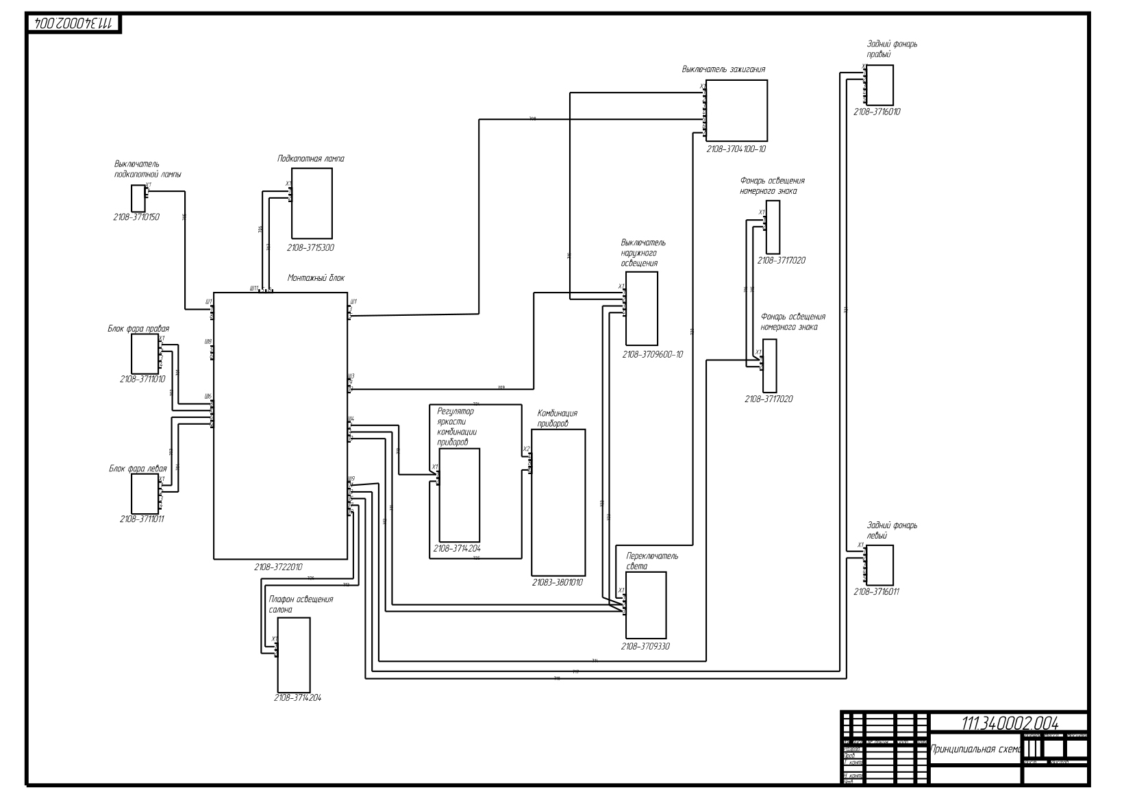
Designing electrical circuits is one of the most important stages of work. From it depend: the quality of the product, the timing and cost of designing the entire electrical system as a whole. One of the main documents of the project documentation is a schematic diagram, which determines the basic composition of electrical equipment and the relationships between them. Based on the schematic diagram, the following schemes are created: wiring diagram, wiring diagram and all technological documentation.
In the Electrical Systems Design module on the 3DExperience platform, you can create or edit HGO (graphic symbols) for various electrical components, such as equipment or devices, instrument connectors, cable connectors, various types of wires, etc. For multidisciplinary equipment, you can create a different display of HBO.
On the platform it is possible to implement various methods of designing electrical systems for various business processes of an enterprise. As an example, the creation of electrical circuits will be described, starting from the block diagram and ending with the wiring diagram.
In this case, the process of creating electrical systems will consist of the following steps:
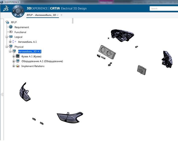
It is necessary to observe a certain structure of the construction tree. The hierarchical tree structure is created using logical components (Logical Reference). Equipment or devices are placed in the first logical component, components for the block diagram in the second, components for the circuit diagram in the third, and components for the circuit diagram in the fourth.
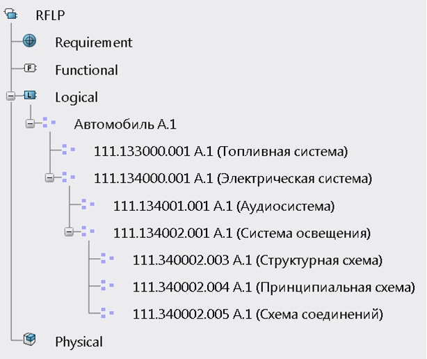
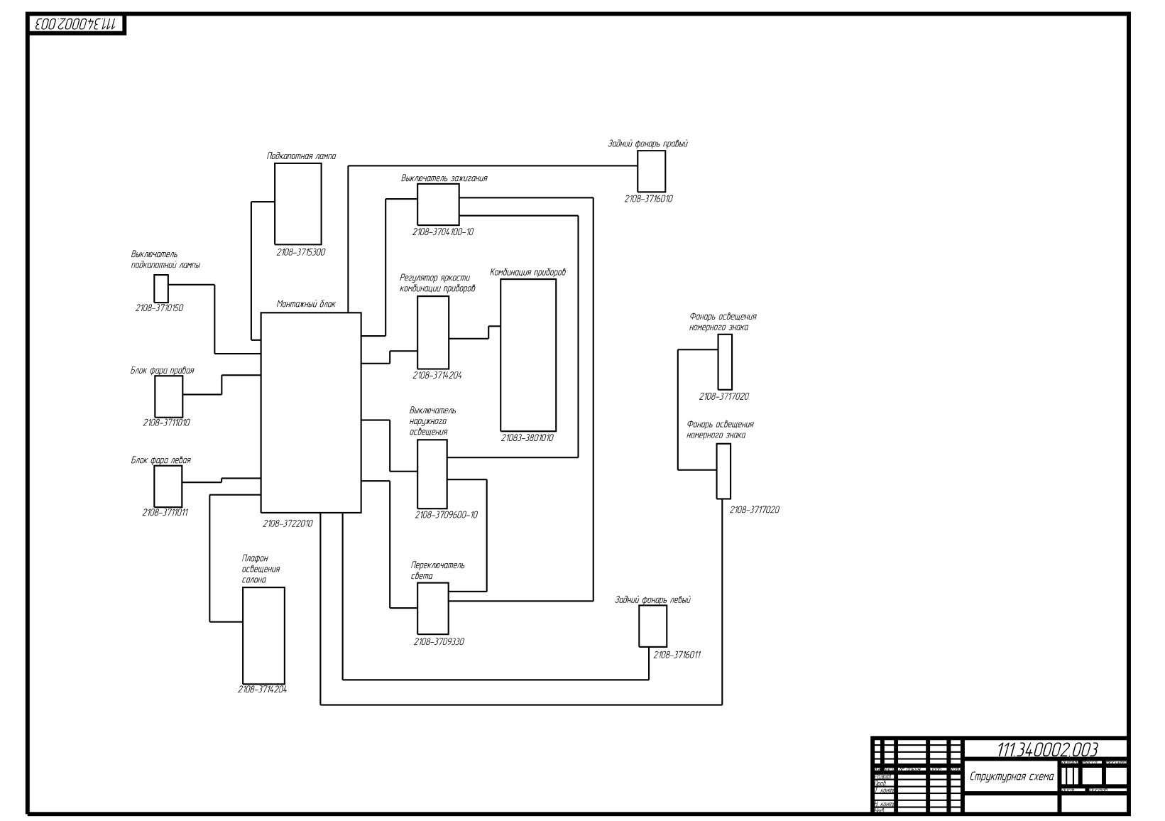
The first step in the design of electrical systems is the definition of a structural scheme, which includes equipment and the relationship between them. All this data is located in a logical component with the name "Structural Diagram".
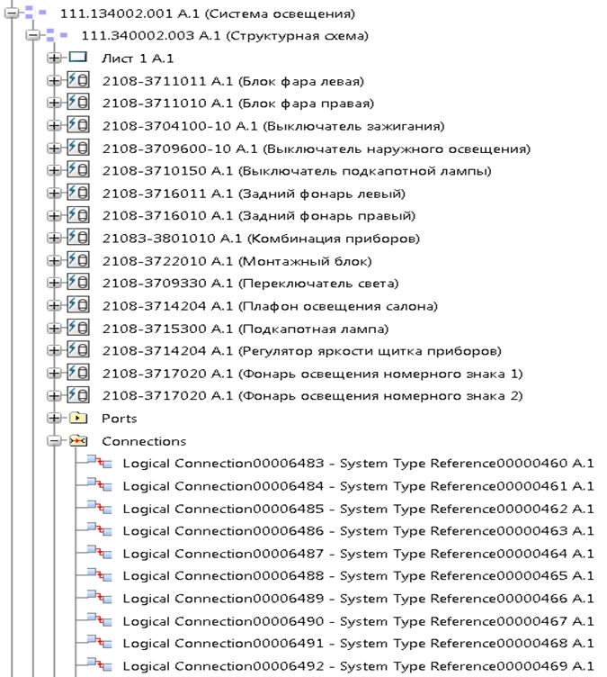
A drawing is used to display the block diagram, which is also located inside this logical component.
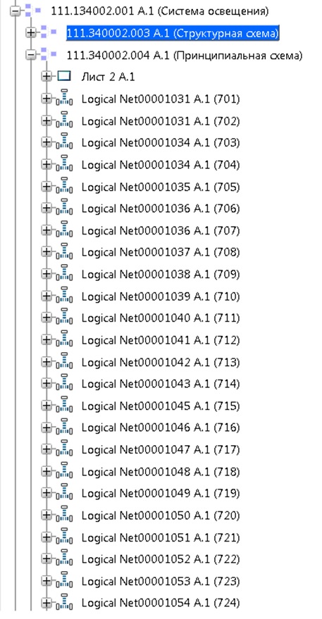
The next step is to create a concept. To do this, a logical component is created in the construction tree with the name “Schematic diagram”.
First, the diagram displays the necessary equipment or devices, and then the instrument connector with contacts is added to them. The equipment can display only used contacts of the instrument connector. After that we create a contact connection between various types of equipment or devices. The created connection carries only the information about the electrical signal.
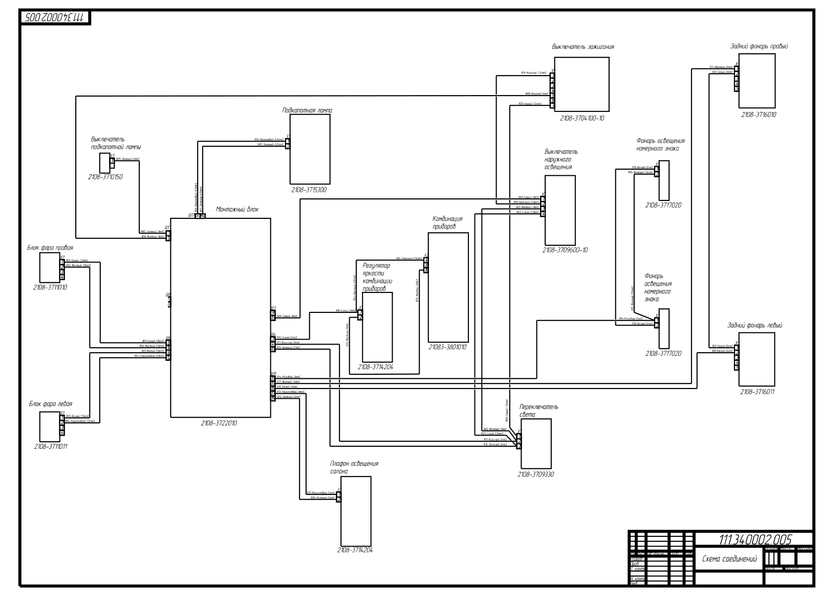
The next step is to create a schematic. To do this, a logical component is created in the build tree with the name "Connection diagram". First, the diagram shows equipment or devices, then instrument connectors. As in the schematic diagram, only the used contacts of the instrument connector can be displayed on the wiring diagram. Then we insert cable connectors into the circuit. As with device connectors, only used contacts can be displayed for cable connectors. Then we create an electrical connection between the cable and instrument connectors. And the final step in creating the schematic is to add wires to the circuit.
To ensure the quality of circuit design, there are special verification tools. One of the tools checks the circuit for integrity, which checks the connection of devices or equipment to each other with the help of wires.

It is important to note that on the 3DExperience platform, you can create any electrical diagrams, ranging from structural diagrams to wiring diagrams, schema analysis, and report generation.
After the development of the electrical circuit, we turn to the stage of three-dimensional design of the electrical system. It includes the following steps:
The Logical to Physical function is used to collect and transfer data from the circuit to three-dimensional space. This function analyzes the electrical circuit, automatically collects the necessary information and provides it to the designer in a convenient form. In the dialog box, data is grouped by type of electrical component (equipment or appliances, connectors, wires, etc.).
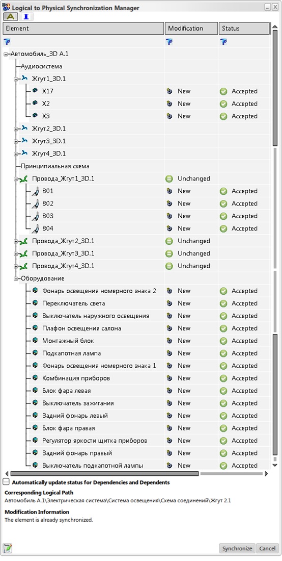
The first stage is the placement of equipment or instruments in three-dimensional space. To do this, we run the Logical tp Physical function, run the analysis of the circuit and select only the equipment or devices that we want to transfer to three-dimensional space. In order to transfer only the equipment, you must select all other elements of the electrical system in the Logical to Physical Synchronization Management dialog box, set the Rejected value in the Status column and click the Synchronize button.
After the equipment has been added to three-dimensional space, it must be placed in the right places.
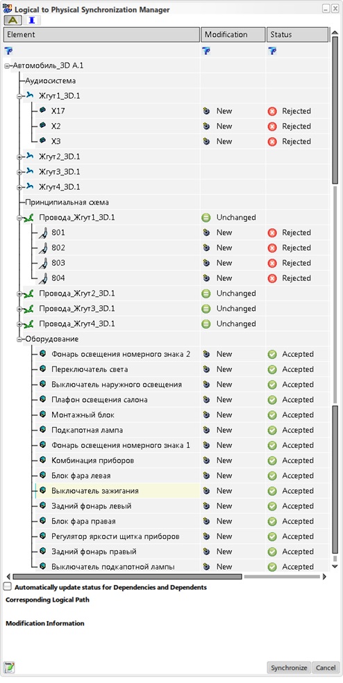
The next step is to add cable connectors to three-dimensional space. The Logical to Physical function is also used for this. It also analyzes the whole circuit in the dialog box in the Modification column opposite to the equipment indicated “Unchanged”, and opposite to the cable connectors and wires indicated “New”.
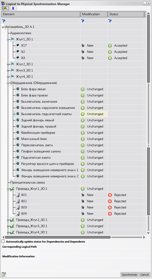
In the dialog box, select all the wires, and also indicate the status "Reject".
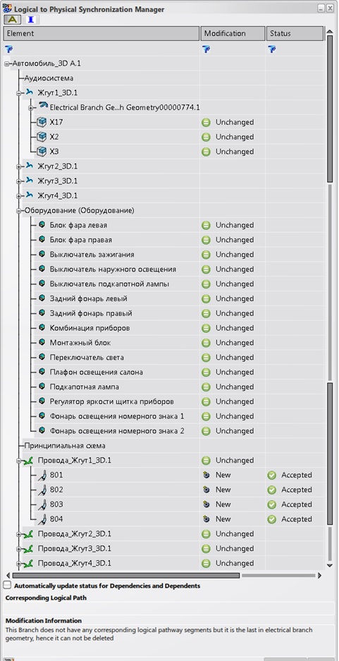
After synchronization, all cable connectors will automatically be placed on the necessary equipment or devices. This behavior is achieved by specifying the same names on the UGO and in the three-dimensional representation of the electrical component and transferring the necessary information from the circuit.
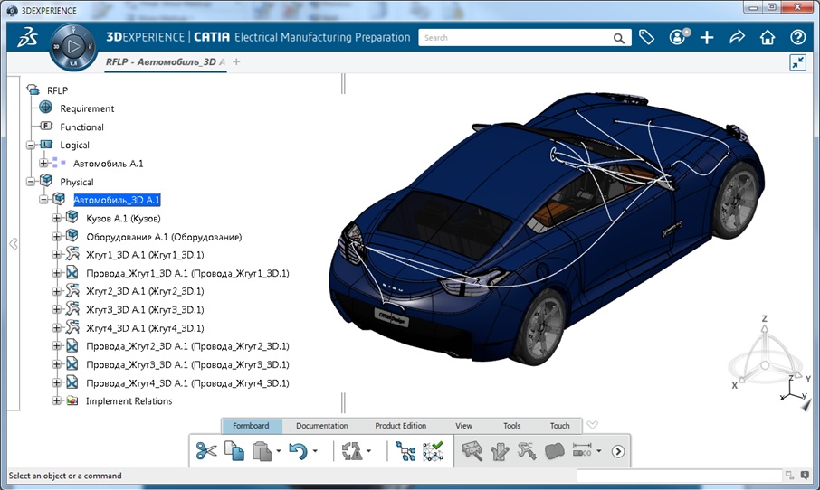
Creating three-dimensional geometry of the harness is possible in two ways:
To create an electrical harness, first choose the cable connector or connector casing, then all the necessary supporting elements, and the last element is to select the cable connector or its casing. When creating an electrical harness, you can create a branch that begins on the harness, passes through the necessary supporting elements, and ends on the cable connector or on its casing.
When creating an electrical harness by the second method, you must select the cable connector or its housing, then approximately indicate the points through which the electrical harness must pass, and last choose the cable connector. Next, we place all the supporting elements for this bundle, and a special function allows you to automatically skip the geometry of the bundle through these supporting elements.
When equipment is connected to a cable connector, when creating a bundle using cable connectors and supporting elements, electrical and geometric relationships are created between all objects. Moving any element of the electrical system in space leads to a geometric rebuilding of the entire system as a whole.
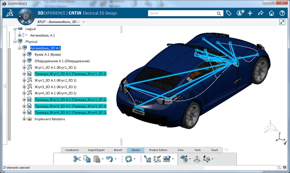
And the last stage is the transfer of information about the wires from the circuit in 3D. To accomplish this operation, the Logical to Physical function is also used. After analyzing the circuit, the dialog box will show that the equipment or devices, cable connectors are already placed on the circuit, and there are no wires yet. In the process of synchronizing the wires from the circuit in 3D, the following information is transmitted - from what contact of the cable connector did the wire go and what contact of the cable connector did it come in, as well as the characteristics of each wire.
After synchronization in 3D, straight lines appear, showing where and where the wires go.
Launching the trace function, we specify the three-dimensional geometry of the bundle; wires will be laid taking into account the three-dimensional geometry of the harness, the diameter of the electrical harness will be updated depending on the number of wires in each segment of the harness.
We conclude that when developing a three-dimensional representation of the harness you will have a large arsenal of tools and functions available. Convenient process of separation of the project's working sectors for the implementation of complex work, which will not be violated by changes made by another specialist.
When we have coped with the design of the electrical circuit and the creation of three-dimensional geometry, go to the next stage of work. Preparation for production.
At this design stage, on the basis of the three-dimensional geometry of the electrical harness, its flat representation is created, which consists of the following steps:
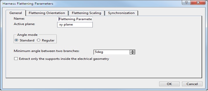
Before creating an electrical harness sweep, you must create a process assembly and determine the sweep parameters. The parameters are the plane, the ability to transfer support elements and their orientation on the sweep plane.
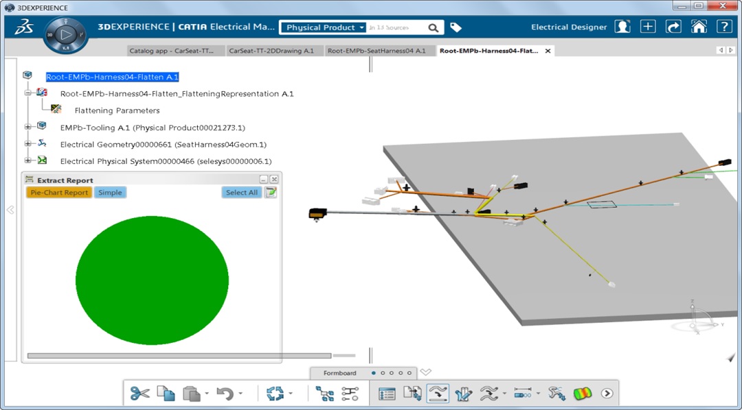
Next, you need to extract and duplicate the three-dimensional geometry of the electrical harness from the main assembly to the process assembly. When performing this operation, all elements that are connected to the harness (cable connectors, assembled cable connectors, connector covers, protective elements of the harness) are determined and transferred to the process assembly.
In the process of performing extraction and duplication, an analysis is automatically launched, which informs the engineer about problems when duplicating all elements of the electrical harness. If the circumference is completely green, then no problems were found when duplicating the geometry.
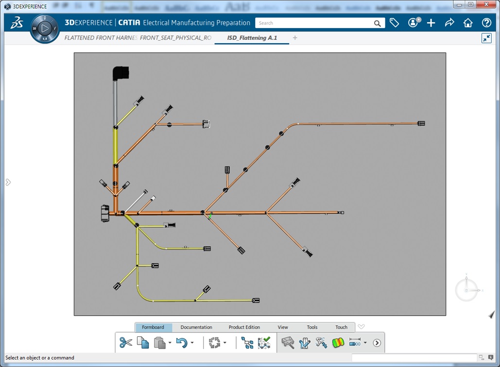
Using the tools, we modify the electrical scan of the electrical harness so that it fits completely over a certain area. The following options are available when modifying a sweep:
Now go to the release of design documentation. Based on the sweep of an electrical harness a drawing is created. The creation is completely automatic. Arrangement of annotations in the drawing, the creation of a table of compounds occurs automatically.
If the equipment was moved in space, respectively, the length of the harness segment may increase or decrease and all these changes will also be made on the scan and on the drawing.

And thus, we can note that the platform prepares all the necessary files and working documents for creating the product. The platform provides a complete automatic process for the preparation of drawings and diagrams, checks for errors and makes a control analysis of the efficiency of the circuit. Eliminates the slightest inaccuracies and errors due to the smooth process of transition from one stage to another.
The 3DEXPERIENCE platform from Dassault Systèmes implements the end-to-end electrical system design process, from creating circuits to pre-production through digital information continuity. The whole course of work is available for viewing in real time. Participants can make edits and changes without interfering with the work of another specialist. And the main feature of the platform, we celebrate integration.
This process allows you to work in seamless mode from the beginning of the project to its completion, and the data between the stages are automatically synchronized.
Author: Semyon Lyakh, Dassault Systèmes Technical Specialist. semen.lyakh@3ds.com
At the current time, most enterprises use a typical electrical circuit design process, consisting of three stages:
- Development of the scheme;
- 3D design;
- Preparation harness for production.
These processes are carried out, as a rule, in different programs and such project spacing causes tangible difficulties. For example, when designing electrical circuits most often use specialized programs from the company Zuken, IGE-XAO and others. Further, moving to work with a three-dimensional representation of the electrical system, programs like CATIA V5 can be involved. And this all ends at the stage of preparing the electric cable for the production process itself. In this case, a diverse set of software is used to solve the problem.
As you can see, all these steps take a lot of time, financial costs and do not provide a guarantee for a really high-quality final product. The main problem of this typical process is the lack of full integration, which transfers data between all the design stages.
Next, we will explain and show the end-to-end design process using the example of step-by-step work in all three stages.
Electrical circuit design
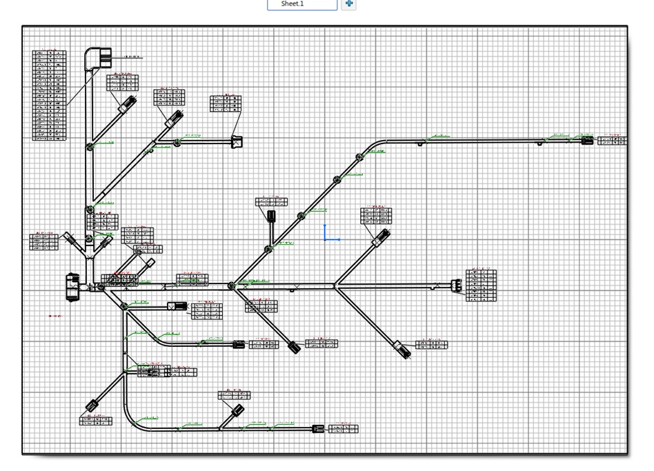
Designing electrical circuits is one of the most important stages of work. From it depend: the quality of the product, the timing and cost of designing the entire electrical system as a whole. One of the main documents of the project documentation is a schematic diagram, which determines the basic composition of electrical equipment and the relationships between them. Based on the schematic diagram, the following schemes are created: wiring diagram, wiring diagram and all technological documentation.
In the Electrical Systems Design module on the 3DExperience platform, you can create or edit HGO (graphic symbols) for various electrical components, such as equipment or devices, instrument connectors, cable connectors, various types of wires, etc. For multidisciplinary equipment, you can create a different display of HBO.
On the platform it is possible to implement various methods of designing electrical systems for various business processes of an enterprise. As an example, the creation of electrical circuits will be described, starting from the block diagram and ending with the wiring diagram.
In this case, the process of creating electrical systems will consist of the following steps:
- definition of the structural scheme;
- concept definition;
- wiring diagram definition.
It is necessary to observe a certain structure of the construction tree. The hierarchical tree structure is created using logical components (Logical Reference). Equipment or devices are placed in the first logical component, components for the block diagram in the second, components for the circuit diagram in the third, and components for the circuit diagram in the fourth.
The first step in the design of electrical systems is the definition of a structural scheme, which includes equipment and the relationship between them. All this data is located in a logical component with the name "Structural Diagram".
A drawing is used to display the block diagram, which is also located inside this logical component.
The next step is to create a concept. To do this, a logical component is created in the construction tree with the name “Schematic diagram”.
First, the diagram displays the necessary equipment or devices, and then the instrument connector with contacts is added to them. The equipment can display only used contacts of the instrument connector. After that we create a contact connection between various types of equipment or devices. The created connection carries only the information about the electrical signal.
The next step is to create a schematic. To do this, a logical component is created in the build tree with the name "Connection diagram". First, the diagram shows equipment or devices, then instrument connectors. As in the schematic diagram, only the used contacts of the instrument connector can be displayed on the wiring diagram. Then we insert cable connectors into the circuit. As with device connectors, only used contacts can be displayed for cable connectors. Then we create an electrical connection between the cable and instrument connectors. And the final step in creating the schematic is to add wires to the circuit.
To ensure the quality of circuit design, there are special verification tools. One of the tools checks the circuit for integrity, which checks the connection of devices or equipment to each other with the help of wires.
It is important to note that on the 3DExperience platform, you can create any electrical diagrams, ranging from structural diagrams to wiring diagrams, schema analysis, and report generation.
Transferring data from the circuit to three-dimensional space
After the development of the electrical circuit, we turn to the stage of three-dimensional design of the electrical system. It includes the following steps:
- placement of equipment or devices in three-dimensional space (data transfer from the diagram in 3D);
- placement of cable connectors (data transfer from the circuit to 3D);
- placement of fasteners for the harness (work only in 3D);
- creation of three-dimensional geometry of the harness (work only in 3D);
- wiring along the harness (data transfer from the circuit to 3D).
The Logical to Physical function is used to collect and transfer data from the circuit to three-dimensional space. This function analyzes the electrical circuit, automatically collects the necessary information and provides it to the designer in a convenient form. In the dialog box, data is grouped by type of electrical component (equipment or appliances, connectors, wires, etc.).
The first stage is the placement of equipment or instruments in three-dimensional space. To do this, we run the Logical tp Physical function, run the analysis of the circuit and select only the equipment or devices that we want to transfer to three-dimensional space. In order to transfer only the equipment, you must select all other elements of the electrical system in the Logical to Physical Synchronization Management dialog box, set the Rejected value in the Status column and click the Synchronize button.
After the equipment has been added to three-dimensional space, it must be placed in the right places.
The next step is to add cable connectors to three-dimensional space. The Logical to Physical function is also used for this. It also analyzes the whole circuit in the dialog box in the Modification column opposite to the equipment indicated “Unchanged”, and opposite to the cable connectors and wires indicated “New”.
In the dialog box, select all the wires, and also indicate the status "Reject".
After synchronization, all cable connectors will automatically be placed on the necessary equipment or devices. This behavior is achieved by specifying the same names on the UGO and in the three-dimensional representation of the electrical component and transferring the necessary information from the circuit.
Creating three-dimensional geometry of the harness is possible in two ways:
- The first way is to place the supporting elements and then create the three-dimensional geometry of the harness.
- The second method is the preliminary creation of the three-dimensional geometry of the harness, the determination of the optimal location of the supporting elements, and then the transmission of the electric harness through the spaced supporting elements.
- The third method is a combination of the first two methods.
To create an electrical harness, first choose the cable connector or connector casing, then all the necessary supporting elements, and the last element is to select the cable connector or its casing. When creating an electrical harness, you can create a branch that begins on the harness, passes through the necessary supporting elements, and ends on the cable connector or on its casing.
When creating an electrical harness by the second method, you must select the cable connector or its housing, then approximately indicate the points through which the electrical harness must pass, and last choose the cable connector. Next, we place all the supporting elements for this bundle, and a special function allows you to automatically skip the geometry of the bundle through these supporting elements.
When equipment is connected to a cable connector, when creating a bundle using cable connectors and supporting elements, electrical and geometric relationships are created between all objects. Moving any element of the electrical system in space leads to a geometric rebuilding of the entire system as a whole.
And the last stage is the transfer of information about the wires from the circuit in 3D. To accomplish this operation, the Logical to Physical function is also used. After analyzing the circuit, the dialog box will show that the equipment or devices, cable connectors are already placed on the circuit, and there are no wires yet. In the process of synchronizing the wires from the circuit in 3D, the following information is transmitted - from what contact of the cable connector did the wire go and what contact of the cable connector did it come in, as well as the characteristics of each wire.
After synchronization in 3D, straight lines appear, showing where and where the wires go.
Launching the trace function, we specify the three-dimensional geometry of the bundle; wires will be laid taking into account the three-dimensional geometry of the harness, the diameter of the electrical harness will be updated depending on the number of wires in each segment of the harness.
We conclude that when developing a three-dimensional representation of the harness you will have a large arsenal of tools and functions available. Convenient process of separation of the project's working sectors for the implementation of complex work, which will not be violated by changes made by another specialist.
Preparation of electrical harness for production
When we have coped with the design of the electrical circuit and the creation of three-dimensional geometry, go to the next stage of work. Preparation for production.
At this design stage, on the basis of the three-dimensional geometry of the electrical harness, its flat representation is created, which consists of the following steps:
- Creation of technological assembly
- Definition of sweep parameters
- Extraction and duplication of the three-dimensional geometry of the electric harness
- Unfolding electrical harness on the plane
- Sweep Modification
- Release of design documentation
Before creating an electrical harness sweep, you must create a process assembly and determine the sweep parameters. The parameters are the plane, the ability to transfer support elements and their orientation on the sweep plane.
Next, you need to extract and duplicate the three-dimensional geometry of the electrical harness from the main assembly to the process assembly. When performing this operation, all elements that are connected to the harness (cable connectors, assembled cable connectors, connector covers, protective elements of the harness) are determined and transferred to the process assembly.
In the process of performing extraction and duplication, an analysis is automatically launched, which informs the engineer about problems when duplicating all elements of the electrical harness. If the circumference is completely green, then no problems were found when duplicating the geometry.
Using the tools, we modify the electrical scan of the electrical harness so that it fits completely over a certain area. The following options are available when modifying a sweep:
- Rotation of the segment relative to the branch point;
- The bend of the harness segment at a certain point and with a certain bend radius;
- Parallel and perpendicular arrangement of one segment of the harness relative to the other.
Now go to the release of design documentation. Based on the sweep of an electrical harness a drawing is created. The creation is completely automatic. Arrangement of annotations in the drawing, the creation of a table of compounds occurs automatically.
If the equipment was moved in space, respectively, the length of the harness segment may increase or decrease and all these changes will also be made on the scan and on the drawing.
And thus, we can note that the platform prepares all the necessary files and working documents for creating the product. The platform provides a complete automatic process for the preparation of drawings and diagrams, checks for errors and makes a control analysis of the efficiency of the circuit. Eliminates the slightest inaccuracies and errors due to the smooth process of transition from one stage to another.
The 3DEXPERIENCE platform from Dassault Systèmes implements the end-to-end electrical system design process, from creating circuits to pre-production through digital information continuity. The whole course of work is available for viewing in real time. Participants can make edits and changes without interfering with the work of another specialist. And the main feature of the platform, we celebrate integration.
This process allows you to work in seamless mode from the beginning of the project to its completion, and the data between the stages are automatically synchronized.
Author: Semyon Lyakh, Dassault Systèmes Technical Specialist. semen.lyakh@3ds.com