Interrupts from external devices in the x86 system. Part 1. The evolution of interrupt controllers
In this article I would like to consider the mechanisms for delivering interrupts from external devices on the x86 system and try to answer the following questions:
If you are interested in an answer to any of these questions, or you just want to familiarize yourself with the evolution of the x86 interrupt controllers, welcome under cat.
We all know what interruption is. For those who do not, quote from Wikipedia:
What are they needed for? Suppose we want to perform some action with the input packet for the network card when it comes. In order not to constantly ask the network card “do you have a new package?” And not to waste processor resources on it, you can use the IRQ interrupt. The interrupt line of the device is connected to the INTR line of the processor, and when receiving a packet, the network card “pulls” this line. The processor understands that there is information for it and reads the packet.
But what if there are a lot of devices? You will not get enough on all external devices of processor legs.
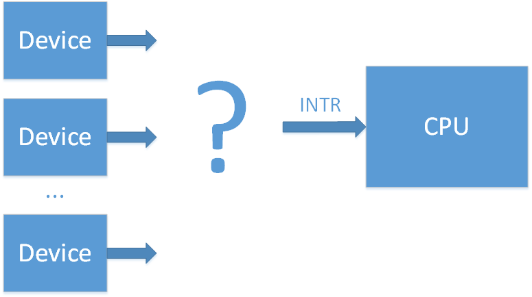
To solve this problem, they invented a microcircuit - an interrupt controller.
( wiki / osdev ) The
first was the Intel 8259 PIC chip . 8 input lines (IRQ0-7), and one output, connecting the controller with the INTR line of the processor. When an interrupt from a device occurs, the 8259 pulls the INTR line, the processor realizes that some device signals an interrupt and polls the PIC in order to understand which IRQx is causing the interrupt. An additional delay appears for this poll, but the number of interrupt lines increases to 8.

However, 8 lines quickly turned out to be small, and in order to increase their number they began to use 2 8259 controllers (master and slave) connected in cascade (Dual PIC).
IRQs from 0 to 7 are processed by the first Intel 8259 PIC (master), and IRQs from 8 to 15 by the second 8259 PIC (slave). The occurrence of a CPU interrupt is signaled only by the master. If an interrupt occurs on lines 8-15, the second PIC (slave) signals an interrupt to the master via IRQ 2, and the latter in turn signals the CPU. This cascade interrupt takes away one of the 16 lines, but ultimately results in 15 available interrupts for devices.

The scheme is established, and that is what they mean when they talk now about the PIC (Programm Interrupt Controller). Subsequently, the 8259 controllers received some improvements, and they began to be called 8259A, and this scheme became part of the chipset. At a time when the main bus for connecting external devices was the ISA bus, such a system as a whole was enough. It was necessary only to ensure that different devices did not connect to the same IRQ line in order to avoid conflicts, since ISA interrupts are not shared.
Typically, the interrupt layout for devices was more or less standard.
Example (taken from here ):
IRQ 0 - system timer
IRQ 1 - keyboard controller
IRQ 2 - cascade (interrupt from the slave controller)
IRQ 3 - serial port COM2
IRQ 4 - serial port COM1
IRQ 5 - parallel port 2 and 3
IRQ 6 - floppy controller
IRQ 7 - parallel port 1
IRQ 8 - RTC timer
IRQ 9 - ACPI
IRQ 10 - open / SCSI / NIC
IRQ 11 - open / SCSI / NIC
IRQ 12 - mouse controller
IRQ 13 - math co-processor
IRQ 14 - ATA channel 1
IRQ 15 - ATA channel 2
Configuration and work with 8259 chips is carried out through I / O ports:
→ Documentation on the 8259A can be found here.
The PCI bus has come to replace the ISA bus. And the number of devices clearly became higher than 15, plus, in contrast to the static ISA bus, in this case, devices can be added to the system dynamically. But fortunately, in this bus interrupts can be shared (that is, several devices can be connected to the same IRQ line). As a result, in order to solve the problem of lack of IRQ lines, it was decided to group interrupts from all PCI devices into PIRQ (Programmable Interrupt Request) lines.
Suppose we have 4 interrupt lines freely on the PIC controller, and PCI devices 20 pieces. We connect interrupts of 5 devices to the PIRQx line and connect the PIRQx lines to the controller. When an interrupt occurs on the PIRQx line, the processor will have to interrogate all devices connected to this line in order to understand from whom the interruption has come, but in general it solves the problem. The device interconnecting PCI interrupt lines on a PIRQ line is often called a PIR router.
In this method, you must ensure that the PIRQx lines are not connected to the IRQx lines on which the ISA interrupts are already set up (as this will cause conflicts), and that the PIRQx lines are balanced (after all, the more devices we connected to one PIRQ line, the more devices we need will interrogate the processor to understand which of these devices caused the interruption).

Note : in the picture, the mapping of the PCI device -> PIR is depicted in the abstract, because in reality it is somewhat more complicated. In reality, each PCI device has 4 interrupt lines (INTA, INTB, INTC, INTD). Each PCI device (device) can have up to 8 functions (functions), and for each function there is already one INTx interrupt. Which INTx will be pulled by each device function is determined by the chipset configuration.
In essence, functions are separate logical blocks. For example, in one PCI device there may be the Smbus controller function, the SATA controller function, the LPC bridge function. On the OS side, each function is as a separate device with its own PCI Config configuration space.
Information about routing interrupts on the PIC controller BIOS was transferred by the OS using the $ PIR table and using the 3Ch (INT_LN Interrupt Line (R / W)) and 3Dh (INT_PN Interrupt Pin (RO)) registers of the PCI configuration space for each function. The specification for the $ PIR table used to be on the Intel site , but now it is no longer there. The contents of the rows in the $ PIR table can be understood from the PCI BIOS Specification [4.2.2. Get PCI Interrupt Routing Options] or read here.
( wiki , osdev ) The
previous method worked until multiprocessing systems appeared. The fact is that in its device PIC can transmit interrupts only to one main processor. And I would like the load on processors from interrupt handling to be balanced. The solution to this problem was the new APIC interface (Advanced PIC).
For each processor, a special LAPIC controller (Local APIC) is added, and an I / O APIC controller is added to route interrupts from devices . All of these controllers are combined into a common bus with the name APIC (new systems are now connected via a standard system bus).
When an interrupt from the device arrives at the I / O APIC pin, the controller sends the interrupt to the LAPIC of one of the processors. The presence of I / O APIC allows balanced distribution of interrupts from external devices between processors.
The first APIC chip was 82489DX , it was a separate chip that combines LAPIC and I / O APIC. To create a system of 2 processors, 3 such chips were needed. 2 would function as LAPIC and one as I / O APIC. Later, the LAPIC functionality was directly incorporated into the processors, and the I / O APIC functionality was framed in an 82093AA chip.
I / O APIC 82093AAcontained 24 input outputs, and the APIC architecture could support up to 16 CPUs. To maintain compatibility with older systems, interrupts 0 ~ 15 were taken under old ISA interrupts. And interrupts from PCI devices began to output on the line IRQ 16-23. Now you could not think about conflicts of interruptions from ISA and PCI devices. Also, due to the increased number of free interrupt lines, it has also become possible to increase the number of PIRQx lines.

The programming of the I / O APIC and LAPIC is carried out through the MMIO. LAPIC registers are usually located at 0xFEE00000, I / O APIC registers at 0xFEС00000. Although, in principle, all these addresses can be reconfigured.
As in the case of PIC, initially separate chips were later incorporated into the chipset.
In the future, the APIC architecture was upgraded and the new version was called xAPIC (x - extended). Preserved backward compatibility with the previous version. The number of possible CPUs in the system has increased to 256.
The next turn in the development of the architecture is called x2APIC . The number of possible CPUs in the system has increased to 2 ^ 32. The controllers can operate in the xAPIC compatibility mode, or in the new x2APIC mode, where LAPIC is programmed not through MMIO, but through MSR registers (which is much faster). Judging by this link, IOMMU support is required for this mode to work.
It should be noted that there may be several I / O APIC controllers in the system. For example, one for 24 interrupts in the south bridge, the other for 32 in the north bridge. In the context of I / O APIC, interrupts are often referred to as GSI (Global System Interrupt). So in this system will be GSI 0-55.
Is there a built-in LAPIC in the CPU and which architecture can be understood by the bit flags in CPUID.
In order for the system to detect LAPIC and I / O APIC, the BIOS must provide information about them to the system either through the MPtable table (old method) or through the ACPI table (MADT table in this case). In addition to general information, both MPtable and ACPI (this time in the DSDT table) should contain information on interrupt routing, that is, information on which device sits on which interrupt line (similar to $ PIR).
You can read about MPTable in the official specification . Previously, the specification was on the Intel site, and now it can only be found in the archive. The ACPI specification is now located on the UEFI website (current version 6.2 ). It should be noted that using ACPI, you can specify interrupt routing for systems without an APIC (instead of using the $ PIR table).
( wiki )
The previous version with APIC is good, but not without flaws. All these interrupt lines from devices complicate the circuit, and increase the likelihood of errors. PCI express came to replace the PCI bus, in which the interrupt lines were simply decided to be removed. To maintain compatibility, interrupt signals (INTx #) are emulated by separate types of messages. In this scheme, the logical addition of interrupt lines, which was previously made by the physical connection of wires, lay on the shoulders of PCI bridges. However, legacy INTx support for interrupts is only support for backward compatibility with the PCI bus. In fact, PCI express offered a new method for delivering interrupt messages - MSI (Message Signaled Interrupts). In this method, to signal an interrupt, the device simply writes to the MMIO area allocated for the LAPIC processor.
If earlier only one interrupt was allocated to one PCI device (that is, all its functions), now it is now possible to address up to 32 interrupts.
In the case of MSI, there is no sharing for the lines, each interrupt corresponds to its device.
MSI interrupts also solve another problem. Suppose a device conducts a memory-write transaction, and wants to report its completion through an interrupt. But the write transaction can be delayed on the bus during transmission (which the device does not know about), and the interrupt signal will come to the processor earlier. Thus, the CPU will read more invalid data. If MSI is used, information about MSI is transmitted in the same way as data, and it will not be able to arrive earlier.
It should be noted that MSI interrupts cannot work without LAPIC, but using MSI can replace us with I / O APIC (design simplification).
Subsequently, this method received an extension MSI-X. Now each device can have up to 2048 interrupts. And it became possible to specify individually each interrupt on which processor it should be executed. This can be very useful for heavily loaded devices, such as network cards.
MSI support does not require any additional BIOS tables. But the device must report support for MSI in one of the Capability in its PCI Config, and the device driver must support operation with MSI.
In this article, we looked at the evolution of interrupt controllers, and obtained general theoretical information on the delivery of interrupts from external devices in the x86 system.
In the next part, we will look at how to use each of the described controllers in Linux in practice.
- What is a PIC and what is it for?
- What is APIC and what is it for? What are LAPIC and I / O APIC for?
- What is the difference between APIC, xAPIC and x2APIC?
- What is MSI? What are the differences between MSI and MSI-X?
- How are the $ PIR, MPtable, ACPI tables associated with this?
If you are interested in an answer to any of these questions, or you just want to familiarize yourself with the evolution of the x86 interrupt controllers, welcome under cat.
Introduction
We all know what interruption is. For those who do not, quote from Wikipedia:
Interrupt (eng. Interrupt) - a signal from the software or hardware, informing the processor of the occurrence of any event that requires immediate attention. An interrupt notifies the processor of a high-priority event that requires the interruption of the current code executed by the processor. The processor responds by suspending its current activity, maintaining its state and executing a function called an interrupt handler (or an interrupt handler) that reacts to the event and serves it, and then returns control to the interrupted code.In this article, I would like to discuss external interrupts IRQ.
Depending on the source of the signal, interruptions are divided into:
- asynchronous or external (hardware) - events that originate from external hardware devices (for example, peripheral devices) and can occur at any arbitrary moment: a signal from a timer, network card or disk drive, keyboard keys, mouse movement. The fact that such an interrupt occurs in the system is interpreted as an interrupt request (IRQ) - devices report that they require attention from the OS;
- synchronous, or internal - events in the processor itself as a result of violation of some conditions when executing machine code: dividing by zero or stack overflow, accessing invalid memory addresses or invalid operation code;
What are they needed for? Suppose we want to perform some action with the input packet for the network card when it comes. In order not to constantly ask the network card “do you have a new package?” And not to waste processor resources on it, you can use the IRQ interrupt. The interrupt line of the device is connected to the INTR line of the processor, and when receiving a packet, the network card “pulls” this line. The processor understands that there is information for it and reads the packet.
But what if there are a lot of devices? You will not get enough on all external devices of processor legs.
To solve this problem, they invented a microcircuit - an interrupt controller.
Pic
( wiki / osdev ) The
first was the Intel 8259 PIC chip . 8 input lines (IRQ0-7), and one output, connecting the controller with the INTR line of the processor. When an interrupt from a device occurs, the 8259 pulls the INTR line, the processor realizes that some device signals an interrupt and polls the PIC in order to understand which IRQx is causing the interrupt. An additional delay appears for this poll, but the number of interrupt lines increases to 8.
However, 8 lines quickly turned out to be small, and in order to increase their number they began to use 2 8259 controllers (master and slave) connected in cascade (Dual PIC).
IRQs from 0 to 7 are processed by the first Intel 8259 PIC (master), and IRQs from 8 to 15 by the second 8259 PIC (slave). The occurrence of a CPU interrupt is signaled only by the master. If an interrupt occurs on lines 8-15, the second PIC (slave) signals an interrupt to the master via IRQ 2, and the latter in turn signals the CPU. This cascade interrupt takes away one of the 16 lines, but ultimately results in 15 available interrupts for devices.
The scheme is established, and that is what they mean when they talk now about the PIC (Programm Interrupt Controller). Subsequently, the 8259 controllers received some improvements, and they began to be called 8259A, and this scheme became part of the chipset. At a time when the main bus for connecting external devices was the ISA bus, such a system as a whole was enough. It was necessary only to ensure that different devices did not connect to the same IRQ line in order to avoid conflicts, since ISA interrupts are not shared.
Typically, the interrupt layout for devices was more or less standard.
Example (taken from here ):
IRQ 0 - system timer
IRQ 1 - keyboard controller
IRQ 2 - cascade (interrupt from the slave controller)
IRQ 3 - serial port COM2
IRQ 4 - serial port COM1
IRQ 5 - parallel port 2 and 3
IRQ 6 - floppy controller
IRQ 7 - parallel port 1
IRQ 8 - RTC timer
IRQ 9 - ACPI
IRQ 10 - open / SCSI / NIC
IRQ 11 - open / SCSI / NIC
IRQ 12 - mouse controller
IRQ 13 - math co-processor
IRQ 14 - ATA channel 1
IRQ 15 - ATA channel 2
Configuration and work with 8259 chips is carried out through I / O ports:
| Chip | Register | I / O port |
|---|---|---|
| Master PIC | Command | 0x0020 |
| Master PIC | Data | 0x0021 |
| Slave pic | Command | 0x00A0 |
| Slave pic | Data | 0x00A1 |
→ Documentation on the 8259A can be found here.
The PCI bus has come to replace the ISA bus. And the number of devices clearly became higher than 15, plus, in contrast to the static ISA bus, in this case, devices can be added to the system dynamically. But fortunately, in this bus interrupts can be shared (that is, several devices can be connected to the same IRQ line). As a result, in order to solve the problem of lack of IRQ lines, it was decided to group interrupts from all PCI devices into PIRQ (Programmable Interrupt Request) lines.
Suppose we have 4 interrupt lines freely on the PIC controller, and PCI devices 20 pieces. We connect interrupts of 5 devices to the PIRQx line and connect the PIRQx lines to the controller. When an interrupt occurs on the PIRQx line, the processor will have to interrogate all devices connected to this line in order to understand from whom the interruption has come, but in general it solves the problem. The device interconnecting PCI interrupt lines on a PIRQ line is often called a PIR router.
In this method, you must ensure that the PIRQx lines are not connected to the IRQx lines on which the ISA interrupts are already set up (as this will cause conflicts), and that the PIRQx lines are balanced (after all, the more devices we connected to one PIRQ line, the more devices we need will interrogate the processor to understand which of these devices caused the interruption).
Note : in the picture, the mapping of the PCI device -> PIR is depicted in the abstract, because in reality it is somewhat more complicated. In reality, each PCI device has 4 interrupt lines (INTA, INTB, INTC, INTD). Each PCI device (device) can have up to 8 functions (functions), and for each function there is already one INTx interrupt. Which INTx will be pulled by each device function is determined by the chipset configuration.
In essence, functions are separate logical blocks. For example, in one PCI device there may be the Smbus controller function, the SATA controller function, the LPC bridge function. On the OS side, each function is as a separate device with its own PCI Config configuration space.
Information about routing interrupts on the PIC controller BIOS was transferred by the OS using the $ PIR table and using the 3Ch (INT_LN Interrupt Line (R / W)) and 3Dh (INT_PN Interrupt Pin (RO)) registers of the PCI configuration space for each function. The specification for the $ PIR table used to be on the Intel site , but now it is no longer there. The contents of the rows in the $ PIR table can be understood from the PCI BIOS Specification [4.2.2. Get PCI Interrupt Routing Options] or read here.
APIC
( wiki , osdev ) The
previous method worked until multiprocessing systems appeared. The fact is that in its device PIC can transmit interrupts only to one main processor. And I would like the load on processors from interrupt handling to be balanced. The solution to this problem was the new APIC interface (Advanced PIC).
For each processor, a special LAPIC controller (Local APIC) is added, and an I / O APIC controller is added to route interrupts from devices . All of these controllers are combined into a common bus with the name APIC (new systems are now connected via a standard system bus).
When an interrupt from the device arrives at the I / O APIC pin, the controller sends the interrupt to the LAPIC of one of the processors. The presence of I / O APIC allows balanced distribution of interrupts from external devices between processors.
The first APIC chip was 82489DX , it was a separate chip that combines LAPIC and I / O APIC. To create a system of 2 processors, 3 such chips were needed. 2 would function as LAPIC and one as I / O APIC. Later, the LAPIC functionality was directly incorporated into the processors, and the I / O APIC functionality was framed in an 82093AA chip.
I / O APIC 82093AAcontained 24 input outputs, and the APIC architecture could support up to 16 CPUs. To maintain compatibility with older systems, interrupts 0 ~ 15 were taken under old ISA interrupts. And interrupts from PCI devices began to output on the line IRQ 16-23. Now you could not think about conflicts of interruptions from ISA and PCI devices. Also, due to the increased number of free interrupt lines, it has also become possible to increase the number of PIRQx lines.
The programming of the I / O APIC and LAPIC is carried out through the MMIO. LAPIC registers are usually located at 0xFEE00000, I / O APIC registers at 0xFEС00000. Although, in principle, all these addresses can be reconfigured.
As in the case of PIC, initially separate chips were later incorporated into the chipset.
In the future, the APIC architecture was upgraded and the new version was called xAPIC (x - extended). Preserved backward compatibility with the previous version. The number of possible CPUs in the system has increased to 256.
The next turn in the development of the architecture is called x2APIC . The number of possible CPUs in the system has increased to 2 ^ 32. The controllers can operate in the xAPIC compatibility mode, or in the new x2APIC mode, where LAPIC is programmed not through MMIO, but through MSR registers (which is much faster). Judging by this link, IOMMU support is required for this mode to work.
It should be noted that there may be several I / O APIC controllers in the system. For example, one for 24 interrupts in the south bridge, the other for 32 in the north bridge. In the context of I / O APIC, interrupts are often referred to as GSI (Global System Interrupt). So in this system will be GSI 0-55.
Is there a built-in LAPIC in the CPU and which architecture can be understood by the bit flags in CPUID.
In order for the system to detect LAPIC and I / O APIC, the BIOS must provide information about them to the system either through the MPtable table (old method) or through the ACPI table (MADT table in this case). In addition to general information, both MPtable and ACPI (this time in the DSDT table) should contain information on interrupt routing, that is, information on which device sits on which interrupt line (similar to $ PIR).
You can read about MPTable in the official specification . Previously, the specification was on the Intel site, and now it can only be found in the archive. The ACPI specification is now located on the UEFI website (current version 6.2 ). It should be noted that using ACPI, you can specify interrupt routing for systems without an APIC (instead of using the $ PIR table).
MSI
( wiki )
The previous version with APIC is good, but not without flaws. All these interrupt lines from devices complicate the circuit, and increase the likelihood of errors. PCI express came to replace the PCI bus, in which the interrupt lines were simply decided to be removed. To maintain compatibility, interrupt signals (INTx #) are emulated by separate types of messages. In this scheme, the logical addition of interrupt lines, which was previously made by the physical connection of wires, lay on the shoulders of PCI bridges. However, legacy INTx support for interrupts is only support for backward compatibility with the PCI bus. In fact, PCI express offered a new method for delivering interrupt messages - MSI (Message Signaled Interrupts). In this method, to signal an interrupt, the device simply writes to the MMIO area allocated for the LAPIC processor.
If earlier only one interrupt was allocated to one PCI device (that is, all its functions), now it is now possible to address up to 32 interrupts.
In the case of MSI, there is no sharing for the lines, each interrupt corresponds to its device.
MSI interrupts also solve another problem. Suppose a device conducts a memory-write transaction, and wants to report its completion through an interrupt. But the write transaction can be delayed on the bus during transmission (which the device does not know about), and the interrupt signal will come to the processor earlier. Thus, the CPU will read more invalid data. If MSI is used, information about MSI is transmitted in the same way as data, and it will not be able to arrive earlier.
It should be noted that MSI interrupts cannot work without LAPIC, but using MSI can replace us with I / O APIC (design simplification).
Subsequently, this method received an extension MSI-X. Now each device can have up to 2048 interrupts. And it became possible to specify individually each interrupt on which processor it should be executed. This can be very useful for heavily loaded devices, such as network cards.
MSI support does not require any additional BIOS tables. But the device must report support for MSI in one of the Capability in its PCI Config, and the device driver must support operation with MSI.
Conclusion
In this article, we looked at the evolution of interrupt controllers, and obtained general theoretical information on the delivery of interrupts from external devices in the x86 system.
In the next part, we will look at how to use each of the described controllers in Linux in practice.