inter-AS Option AB (D)
In order to run L3VPN between different autonomous systems, you must use the BGP protocol options - A, B or C. If anyone does not know how these options work, then I ask here . Each of these options has both pros and cons. Let us examine each in more detail:
the Option A .
The meaning of this option is that on ASBRs separate vrfs are raised for each client vpn and a subinterface is created through which pure ip routes are exchanged and, through the same subinterfaces, client traffic is forwarded. There are no mpls between ASBRs. Interworking between ASBR occurs, as between PE and CE routers.
The disadvantages of this option are more than obvious:
- in addition to creating vrf on PE routers, it is necessary to create vrf on ASBRs;
- for the exchange of routes between ASBR, it is necessary to raise the routing protocol in each vrf, naturally a large number, for example, bgp-sessions, do not favorably affect the performance of the router;
But, not surprisingly, this scheme has its pluses:
+ since there is pure ip traffic between ASBR, without mpls, you can implement qos and filtering based on the ip header;
+ customer traffic is clearly divided;
+ this option is the most secure of all (for example, if you can raise this option between different providers if you do not want to inject other people's routes into your autonomous system).
But all the same, the cons in this case outweigh the pros (imagine that you need to roll 50-60 vpn-s - the desire to use option A immediately disappears). Therefore, being in his mind, it is unlikely that some engineer will want to raise A.
Option B in the current conditions .
The meaning of this option is that ASBRs exchange vpnv4 routes. Having received a vpnv4 route from a neighboring AS, ASBR generates a new label, sets itself as the next-hop (option Ba), or without changing the next-hop (option Bb) transfers the routes to the reflector (or PE routers immediately, depending on your topology), after which all PE routers have the necessary vpnv4 routes.
The advantages of this approach:
+ only one BGP vpnv4 session is needed to transfer routes between autonomous systems; ASBR is not loaded with routing protocols in vrf;
+ since all prefixes are transmitted within one session, this approach has good scalability (in comparison with option A);
+ when you turn on the new client there is no need to change the configuration to ASBR (except for the filters naturally);
Cons:
- client traffic is transmitted in a common stream with mpls label and it is not possible to apply qos or filtering based on ip header;
- ASBR is loaded, in addition to traffic forwarding, also digesting a large number of vpnv4 routes;
Option C.
The meaning of this option is that the exchange of vpnv4 routes occurs between route reflectors of different autonomous systems in an ebgp-multihop session. ASBRs, in turn, transmit tagged routes (bgp labeled-unicast) to the neighboring autonomous systems to the loopback routers and PE routers. As a result, using labels received from ASBR, PE routers can build end-to-end lsp between themselves, and vrf labels between all PE routers are distributed using routing reflectors.
Pluses of this option:
+ very high scalability
+ does not burden ASBR with unnecessary work (in comparison with other options)
But there are also disadvantages:
- as in option B, client traffic between ASBRs goes in the general flow, though already with two mpls labels, which does not allow qos and filtering traffic between ASBRs based on ip header.
How to combine the possibility of applying filters / qos in one approach and at the same time not to burden ASBR with unnecessary work to maintain a large number of bgp (ospf, isis, rip) neighbors, and to save engineers from complex configurations on ASBR?
So, today we will talk about inter-AS Option AB (D) .
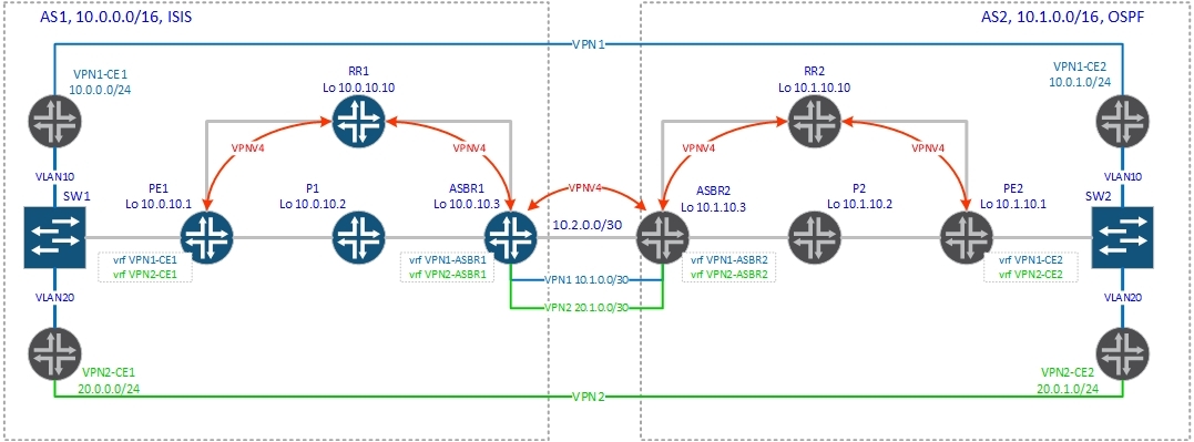
This option, like option A, implies the creation of a separate vrf on ASBRs for each vpn, as well as the creation of a separate subinterface in each vrf, which will be used to transmit client traffic. So far, everything is the same as in standard option A. The significant difference is that no routing protocol in vrf (on ASBR) is launched, and the created subinterfaces are used only for traffic forwarding. How will the routes be exchanged? For this purpose, as in option B, a single vpnv4 session is created between ASBRs, through which vpnv4 routes are transmitted. Actually, we can say that we simultaneously understand both option A and option B between two ASBRs. Let's now move on to a detailed description of the control plane, so that everything falls into place:
1. PE2 generates a vpnv4 route and sends it to the RR2 router.
2. The routreflector validates the received route, and passes it to its customers. In our case, on ASBR2.
3. ASBR2 receives the vpnv4 route and installs it in the routing table of the corresponding vrf, in our case vrf VPN1-ASBR2, according to the configured route-target import.
4. ASBR2 generates a new vpnv4 route, hangs excommunity (route-target) on it, which is indicated for export to vrf VPN1-ASBR2 and transfers the route to ASBR1. Next-hop, as with the usual option B, the address of the ASBR2 router is set (the address of the interface, which is the source for this vpnv4 session).
5. ASBR1 accepts this route and, according to route-target import, installs this route into the routing table of the corresponding vrf, in our case vrf VPN1-ASBR1, replacing next-hop according to the specified in vrf VPN1-ASBR1 (inter-as hybrid next -hop). Replacement is made to the address ASBR2 (joint ASBR2 (vrf VPN1-ASBR2) ==> ASBR1 (vrf VPN1-ASBR1)).
6. ASBR1 generates a new vpnv4 route, hangs on it excommunity (route-target), which is exported to vrf VPN1-ASBR1 and sends the route to the router RR1 (next-hop - ASBR1 loopback)
7. RR1 announces the route to PE1.
8. PE1, having received the route from RR1, installs it in the routing table of the corresponding vrf.
The main thing in this option is that vpnv4 routes to ASBR first fall into vrf and are announced further from this vrf, moreover, it is announced with the excommunity that is specified in vrf for export, and it may differ from the excommunity with which this route was originally announced). Schematically, it looks like this:

That is, the vpnv4 route is transferred from one AS to another in the following sequence: PE2 ==> RR2 ==> ASBR2 ==> ASBR2 (vrf VPN1-ASBR2) ==> ASBR1 ==> ASBR1 (vrf VPN1-ASBR1) ==> RR1 ==> PE1.
So, we will consider all of the above on an example.
Two vrfs are created on PE2:
We will consider the 10.0.1.0/24 route signaling from vrf VPN1-CE2.
Below is vpnv4, a route generated by PE2:
We see that for PE2 the route is local and for this prefix the label is generated 22.
Now PE2 should send this route to the route reflector. Check:
We are announcing two routes (10.1.1.2 is the loopback of the VPN1-CE2 router received via ospf). Further the route is transferred to ASBR2:
We have not enabled the option no bgp default route-target filter, but vrf has been created on ASBR2:
According to route-target import 2: 100, the routes fall into vrf VPN1-ASBR2.
Note: a new command has appeared in the vrf configuration: inter-as-hybrid next-hop. Her appointment will be discussed later.
Check if our route to the network 10.0.1.0/24 is set to the routing table vrf VPN1-ASBR2:
Great, there is a route. So far, everything is as in option A. But in option A, then we must announce pure ip routes from one vrf to another using the routing protocol specially launched in vrf. But in option AB, routes between ASBRs are transmitted via bgp vpnv4 session between ASBRs. Let's see what we announce at ASBR1 on bgp session between ASBRs:
We are announcing 4 routes, but they no longer have the original rd. The announcement with PE1 was with rd 2: 1, and now we are announcing routes with rd 2: 10001. That is, the route has been regenerated on ASBR2. For this to work, you need to give the command: inter-as-hybrid in the settings of the bgp session between ASBRs. This command indicates that this session is intended to transfer vpnv4 routes for option AB (in terms of Cisco - created on ASBR vrf is called option AB vrf).
Продолжим. Проверим маршруты до сети 10.0.1.0/24 на ASBR1:
В выводе у нас два маршрута, один с next-hop 10.2.0.2 — это оригинальный vpnv4 маршрут, полученный от ASBR2; второй с next-hop 10.1.0.2 (via VPN1-ASBR1) — уже измененный маршрут, который будет использоваться для передачи трафика и инсталироваться в таблицу маршрутизации VPN1-ASBR1.
Прошу обратить внимание на то, что ASBR2 как и положено ASBR-ру в опции В сгенерировал метку: в маршруте на ASBR1 есть метка на out: “mpls labels in/out 31/19”. Но данная метка не будет использована для передачи трафика. Это видно из маршрута, который импортируется в таблицу маршрутизации vrf VPN1-ASBR1: в маршруте mpls метки нет: “MPLS label: none” (см вывод ниже):
The next-hop replacement was done thanks to the inter-as-hybrid next-hop command on ASBR1:
If this command is not specified, then the route with the original next-hop from the received vpnv4 route from ASBR2 will be imported into vrf (that is, the next-hop will be the address ASBR2, which is used as a sors for the eBGP session, as in the usual option B ) In our case, on ASBR1 we have these interfaces:
We need vpn1 traffic to forward through the GigabitEthernet3 / 0.10 interface (respectively, vpn2 through GigabitEthernet3 / 0.20). Therefore, in the vrf next-hop settings, the address 10.1.0.2 is indicated - the GigabitEthernet3 / 0.10 interface on ASBR2, which is located in vrf VPN1-ASBR2:
We move on. From vrf VPN1-ASBR1, this route should be announced to the router:
I think you already noticed that this is a new route generated by ASBR1, since here are the routes that ASBR1 received (pay attention to rd):
And here are the routes announced with ASBR1:
Pay attention to rd: was 2: 10001, now 1: 10001. Let's see which vrfs are configured on ASBR1:
I think it’s now clear that the route was generated by ASBR1.
ASBR1 generated label 31 for this prefix:
Further, everything is standard. The route is transmitted from RR1 to PE1:
And PE1 installs its routing table of the corresponding vrf:
The picture below shows the vpn tag signaling process.

Now let's move on to the data plane . Let's make a trace between CE routers:
And the same for vpn2:
PE1 receives the IP packet from the client router and, according to its routing table, hangs up two labels - 31 (vrf label) and 17 or 16 (transport label to ASBR1 depending on how PE1 balances the traffic):
Judging by the trace above, PE1 chooses a route through P1.
P1, having received a packet with tag 17, removes this (top) tag and sends the packet to the Gi1 / 0 interface (link to ASBR1):
ASBR1 processes the packet as a regular PE router - removes the label and sends a clean IP packet to the Gi3 / 0.10 interface:
Having received this packet, ASBR2 works as a PE router, which received the packet from the client CE router - hangs the vrf (22) and transport labels (17 or 19 are equivalent paths again and judging by the trace, the packet goes to RR2):
RR2, as befits a mpls transit router on the penultimate hop, removes the top mark and sends a packet to PE2:
Well, PE2 knows that label 22 indicates that ip lookup should be done in vrf VPN1-CE2:
Next, the packet flies to the client CE router. All labels and operations with them are presented in the figure below.

As a result, we got a hybrid of option A and B, in which we can use qos and filter client traffic between ASBRs as in option A, but at the same time, although we have to configure vrf for each vpn on ASBR and make a separate joint, but there is no need for a separate routing protocol process in each vrf, which naturally reduces the load on the ASBR, which, as in option B, should support only one vpnv4 session with the neighboring ASBR.
Well, in the end, I would like to focus on two important teams:
inter-as-hybrid next-hop in the ip vrf hierarchy - this command is necessary to replace next-hop, if you do not specify it, then the route from next-hop to the joint on which option B. is running is imported into vrf
neighbor 10.2.0.1 inter-as-hybrid - this command indicates that a bgp session has been established between peers to exchange vpnv4 routes for Inter-AS Option AB. This command makes it possible to first import routes into vrf, and then export routes from this vrf further (changing rd and, if necessary, community).
It is important that both of these options must be enabled, otherwise you will either not earn anything or will work, but not how it should work.
Currently, there is only an RFC draft on the AB option. In this article, we met with the option AB on the example of its implementation by Cisco. Write to the PM if you find any shortcomings or think that something needs to be supplemented / described better.
Thank you all for your attention!
the Option A .
The meaning of this option is that on ASBRs separate vrfs are raised for each client vpn and a subinterface is created through which pure ip routes are exchanged and, through the same subinterfaces, client traffic is forwarded. There are no mpls between ASBRs. Interworking between ASBR occurs, as between PE and CE routers.
The disadvantages of this option are more than obvious:
- in addition to creating vrf on PE routers, it is necessary to create vrf on ASBRs;
- for the exchange of routes between ASBR, it is necessary to raise the routing protocol in each vrf, naturally a large number, for example, bgp-sessions, do not favorably affect the performance of the router;
But, not surprisingly, this scheme has its pluses:
+ since there is pure ip traffic between ASBR, without mpls, you can implement qos and filtering based on the ip header;
+ customer traffic is clearly divided;
+ this option is the most secure of all (for example, if you can raise this option between different providers if you do not want to inject other people's routes into your autonomous system).
But all the same, the cons in this case outweigh the pros (imagine that you need to roll 50-60 vpn-s - the desire to use option A immediately disappears). Therefore, being in his mind, it is unlikely that some engineer will want to raise A.
Option B in the current conditions .
The meaning of this option is that ASBRs exchange vpnv4 routes. Having received a vpnv4 route from a neighboring AS, ASBR generates a new label, sets itself as the next-hop (option Ba), or without changing the next-hop (option Bb) transfers the routes to the reflector (or PE routers immediately, depending on your topology), after which all PE routers have the necessary vpnv4 routes.
The advantages of this approach:
+ only one BGP vpnv4 session is needed to transfer routes between autonomous systems; ASBR is not loaded with routing protocols in vrf;
+ since all prefixes are transmitted within one session, this approach has good scalability (in comparison with option A);
+ when you turn on the new client there is no need to change the configuration to ASBR (except for the filters naturally);
Cons:
- client traffic is transmitted in a common stream with mpls label and it is not possible to apply qos or filtering based on ip header;
- ASBR is loaded, in addition to traffic forwarding, also digesting a large number of vpnv4 routes;
Option C.
The meaning of this option is that the exchange of vpnv4 routes occurs between route reflectors of different autonomous systems in an ebgp-multihop session. ASBRs, in turn, transmit tagged routes (bgp labeled-unicast) to the neighboring autonomous systems to the loopback routers and PE routers. As a result, using labels received from ASBR, PE routers can build end-to-end lsp between themselves, and vrf labels between all PE routers are distributed using routing reflectors.
Pluses of this option:
+ very high scalability
+ does not burden ASBR with unnecessary work (in comparison with other options)
But there are also disadvantages:
- as in option B, client traffic between ASBRs goes in the general flow, though already with two mpls labels, which does not allow qos and filtering traffic between ASBRs based on ip header.
How to combine the possibility of applying filters / qos in one approach and at the same time not to burden ASBR with unnecessary work to maintain a large number of bgp (ospf, isis, rip) neighbors, and to save engineers from complex configurations on ASBR?
So, today we will talk about inter-AS Option AB (D) .
This option, like option A, implies the creation of a separate vrf on ASBRs for each vpn, as well as the creation of a separate subinterface in each vrf, which will be used to transmit client traffic. So far, everything is the same as in standard option A. The significant difference is that no routing protocol in vrf (on ASBR) is launched, and the created subinterfaces are used only for traffic forwarding. How will the routes be exchanged? For this purpose, as in option B, a single vpnv4 session is created between ASBRs, through which vpnv4 routes are transmitted. Actually, we can say that we simultaneously understand both option A and option B between two ASBRs. Let's now move on to a detailed description of the control plane, so that everything falls into place:
1. PE2 generates a vpnv4 route and sends it to the RR2 router.
2. The routreflector validates the received route, and passes it to its customers. In our case, on ASBR2.
3. ASBR2 receives the vpnv4 route and installs it in the routing table of the corresponding vrf, in our case vrf VPN1-ASBR2, according to the configured route-target import.
4. ASBR2 generates a new vpnv4 route, hangs excommunity (route-target) on it, which is indicated for export to vrf VPN1-ASBR2 and transfers the route to ASBR1. Next-hop, as with the usual option B, the address of the ASBR2 router is set (the address of the interface, which is the source for this vpnv4 session).
5. ASBR1 accepts this route and, according to route-target import, installs this route into the routing table of the corresponding vrf, in our case vrf VPN1-ASBR1, replacing next-hop according to the specified in vrf VPN1-ASBR1 (inter-as hybrid next -hop). Replacement is made to the address ASBR2 (joint ASBR2 (vrf VPN1-ASBR2) ==> ASBR1 (vrf VPN1-ASBR1)).
6. ASBR1 generates a new vpnv4 route, hangs on it excommunity (route-target), which is exported to vrf VPN1-ASBR1 and sends the route to the router RR1 (next-hop - ASBR1 loopback)
7. RR1 announces the route to PE1.
8. PE1, having received the route from RR1, installs it in the routing table of the corresponding vrf.
The main thing in this option is that vpnv4 routes to ASBR first fall into vrf and are announced further from this vrf, moreover, it is announced with the excommunity that is specified in vrf for export, and it may differ from the excommunity with which this route was originally announced). Schematically, it looks like this:
That is, the vpnv4 route is transferred from one AS to another in the following sequence: PE2 ==> RR2 ==> ASBR2 ==> ASBR2 (vrf VPN1-ASBR2) ==> ASBR1 ==> ASBR1 (vrf VPN1-ASBR1) ==> RR1 ==> PE1.
So, we will consider all of the above on an example.
Two vrfs are created on PE2:
ip vrf VPN1-CE2
 rd 2:1
 route-target export 2:100
 route-target import 1:100
 route-target import 2:100
!
ip vrf VPN2-CE2
 rd 2:2
 route-target export 2:200
 route-target import 1:200
 route-target import 2:200
We will consider the 10.0.1.0/24 route signaling from vrf VPN1-CE2.
Below is vpnv4, a route generated by PE2:
PE2#sh ip bgp vpnv4 rd 2:1 10.0.1.0/24
BGP routing table entry for 2:1:10.0.1.0/24, version 2
Paths: (1 available, best #1, table VPN1-CE2)
  Advertised to update-groups:
     3
  Local
    0.0.0.0 from 0.0.0.0 (10.1.10.1)
      Origin incomplete, metric 0, localpref 100, weight 32768, valid, sourced, best
      Extended Community: RT:2:100 OSPF DOMAIN ID:0x0005:0x000000020200
        OSPF RT:0.0.0.0:2:0 OSPF ROUTER ID:10.0.1.1:0
      mpls labels in/out IPv4 VRF Aggr:22/nolabel(VPN1-CE2)
We see that for PE2 the route is local and for this prefix the label is generated 22.
Now PE2 should send this route to the route reflector. Check:
PE2#show ip bgp vpnv4 rd 2:1 neighbors 10.1.10.10 advertised-routes
BGP table version is 13, local router ID is 10.1.10.1
Status codes: s suppressed, d damped, h history, * valid, > best, i - internal,
              r RIB-failure, S Stale
Origin codes: i - IGP, e - EGP, ? - incomplete
Originating default network 0.0.0.0
   Network          Next Hop            Metric LocPrf Weight Path
Route Distinguisher: 2:1 (default for vrf VPN1-CE2)
*> 10.0.1.0/24      0.0.0.0                  0         32768 ?
*> 10.1.1.2/32      10.0.1.2                 2         32768 ?
Total number of prefixes 2
We are announcing two routes (10.1.1.2 is the loopback of the VPN1-CE2 router received via ospf). Further the route is transferred to ASBR2:
RR2#sh ip bgp vpnv4 rd 2:1 neighbors 10.1.10.3 advertised-routes | i 10.
BGP table version is 37, local router ID is 10.1.10.10
*>i10.0.1.0/24      10.1.10.1                0    100      0 ?
*>i10.1.1.2/32      10.1.10.1                2    100      0 ?
ASBR2#sh ip bgp vpnv4 rd 2:1 10.0.1.0/24
BGP routing table entry for 2:1:10.0.1.0/24, version 100
Paths: (1 available, best #1, no table)
  Not advertised to any peer
  Local
    10.1.10.1 (metric 3) from 10.1.10.10 (10.1.10.10)
      Origin incomplete, metric 0, localpref 100, valid, internal, best
      Extended Community: RT:2:100 OSPF DOMAIN ID:0x0005:0x000000020200
        OSPF RT:0.0.0.0:2:0 OSPF ROUTER ID:10.0.1.1:0
      Originator: 10.1.10.1, Cluster list: 10.1.10.10
      mpls labels in/out nolabel/22
We have not enabled the option no bgp default route-target filter, but vrf has been created on ASBR2:
ip vrf VPN1-ASBR2
 rd 2:10001
 route-target export 2:100
 route-target import 1:100
 route-target import 2:100
 inter-as-hybrid next-hop 10.1.0.1
!
ip vrf VPN2-ASBR2
 rd 2:10002
 route-target export 2:200
 route-target import 1:200
 route-target import 2:200
 inter-as-hybrid next-hop 20.1.0.1
According to route-target import 2: 100, the routes fall into vrf VPN1-ASBR2.
Note: a new command has appeared in the vrf configuration: inter-as-hybrid next-hop. Her appointment will be discussed later.
Check if our route to the network 10.0.1.0/24 is set to the routing table vrf VPN1-ASBR2:
ASBR2#sh ip route vrf VPN1-ASBR2 10.0.1.0
Routing Table: VPN1-ASBR2
Routing entry for 10.0.1.0/24
  Known via "bgp 2", distance 200, metric 0, type internal
  Last update from 10.1.10.1 00:50:46 ago
  Routing Descriptor Blocks:
  * 10.1.10.1 (default), from 10.1.10.10, 00:50:46 ago
      Route metric is 0, traffic share count is 1
      AS Hops 0
      MPLS label: 22
      MPLS Flags: MPLS Required
Great, there is a route. So far, everything is as in option A. But in option A, then we must announce pure ip routes from one vrf to another using the routing protocol specially launched in vrf. But in option AB, routes between ASBRs are transmitted via bgp vpnv4 session between ASBRs. Let's see what we announce at ASBR1 on bgp session between ASBRs:
ASBR2#sh ip bgp vpnv4 all neighbors 10.2.0.1 advertised-routes
BGP table version is 109, local router ID is 10.1.10.3
Status codes: s suppressed, d damped, h history, * valid, > best, i - internal,
              r RIB-failure, S Stale
Origin codes: i - IGP, e - EGP, ? - incomplete
Originating default network 0.0.0.0
   Network          Next Hop            Metric LocPrf Weight Path
Route Distinguisher: 2:10001 (default for vrf VPN1-ASBR2)
*>i10.0.1.0/24      10.1.10.1                0    100      0 ?
*>i10.1.1.2/32      10.1.10.1                2    100      0 ?
Route Distinguisher: 2:10002 (default for vrf VPN2-ASBR2)
*>i20.0.1.0/24      10.1.10.1                0    100      0 ?
*>i20.1.1.2/32      10.1.10.1                2    100      0 ?
Total number of prefixes 4
We are announcing 4 routes, but they no longer have the original rd. The announcement with PE1 was with rd 2: 1, and now we are announcing routes with rd 2: 10001. That is, the route has been regenerated on ASBR2. For this to work, you need to give the command: inter-as-hybrid in the settings of the bgp session between ASBRs. This command indicates that this session is intended to transfer vpnv4 routes for option AB (in terms of Cisco - created on ASBR vrf is called option AB vrf).
ASBR2#sh configuration | b  address-family vpnv4
 address-family vpnv4
  neighbor 10.1.10.10 activate
  neighbor 10.1.10.10 send-community extended
  neighbor 10.2.0.1 activate
  neighbor 10.2.0.1 send-community extended
  neighbor 10.2.0.1 inter-as-hybrid
 exit-address-family
Продолжим. Проверим маршруты до сети 10.0.1.0/24 на ASBR1:
ASBR1#sh ip bgp vpnv4 all 10.0.1.0/24
BGP routing table entry for 1:10001:10.0.1.0/24, version 98
Paths: (1 available, best #1, table VPN1-ASBR1)
  Advertised to update-groups:
     1
  2, imported path from 2:10001:10.0.1.0/24
    10.1.0.2 (via VPN1-ASBR1) from 10.2.0.2 (10.1.10.3)
      Origin incomplete, localpref 100, valid, external, best
      Extended Community: RT:2:100 OSPF DOMAIN ID:0x0005:0x000000020200
        OSPF RT:0.0.0.0:2:0 OSPF ROUTER ID:10.0.1.1:0
      mpls labels in/out 31/19
BGP routing table entry for 2:10001:10.0.1.0/24, version 94
юPaths: (1 available, best #1, no table)
  Not advertised to any peer
  2
    10.2.0.2 from 10.2.0.2 (10.1.10.3)
      Origin incomplete, localpref 100, valid, external, best
      Extended Community: RT:2:100 OSPF DOMAIN ID:0x0005:0x000000020200
        OSPF RT:0.0.0.0:2:0 OSPF ROUTER ID:10.0.1.1:0
      mpls labels in/out nolabel/19
В выводе у нас два маршрута, один с next-hop 10.2.0.2 — это оригинальный vpnv4 маршрут, полученный от ASBR2; второй с next-hop 10.1.0.2 (via VPN1-ASBR1) — уже измененный маршрут, который будет использоваться для передачи трафика и инсталироваться в таблицу маршрутизации VPN1-ASBR1.
Прошу обратить внимание на то, что ASBR2 как и положено ASBR-ру в опции В сгенерировал метку: в маршруте на ASBR1 есть метка на out: “mpls labels in/out 31/19”. Но данная метка не будет использована для передачи трафика. Это видно из маршрута, который импортируется в таблицу маршрутизации vrf VPN1-ASBR1: в маршруте mpls метки нет: “MPLS label: none” (см вывод ниже):
ASBR1#sh ip rou vrf VPN1-ASBR1 10.0.1.0
Routing Table: VPN1-ASBR1
Routing entry for 10.0.1.0/24
  Known via "bgp 1", distance 20, metric 0
  Tag 2, type external
  Last update from 10.1.0.2 on GigabitEthernet3/0.10, 01:14:18 ago
  Routing Descriptor Blocks:
  * 10.1.0.2, from 10.2.0.2, 01:14:18 ago, via GigabitEthernet3/0.10
      Route metric is 0, traffic share count is 1
      AS Hops 1
      Route tag 2
      MPLS label: none
The next-hop replacement was done thanks to the inter-as-hybrid next-hop command on ASBR1:
ip vrf VPN1-ASBR1
 rd 1:10001
 route-target export 1:100
 route-target import 1:100
 route-target import 2:100
 inter-as-hybrid next-hop 10.1.0.2
If this command is not specified, then the route with the original next-hop from the received vpnv4 route from ASBR2 will be imported into vrf (that is, the next-hop will be the address ASBR2, which is used as a sors for the eBGP session, as in the usual option B ) In our case, on ASBR1 we have these interfaces:
ASBR1#sh int description | i Gi3
Gi3/0                          up             up       "to ASBR2 | AS2"
Gi3/0.2                        up             up       "to ASBR2 | vpnv4 routes only"
Gi3/0.10                       up             up       "for VPN1 only"
Gi3/0.20                       up             up       "for VPN2 only"
ASBR1#sh ip int brief | i 3/0
GigabitEthernet3/0         unassigned      YES NVRAM  up                    up
GigabitEthernet3/0.2       10.2.0.1        YES NVRAM  up                    up
GigabitEthernet3/0.10      10.1.0.1        YES NVRAM  up                    up
GigabitEthernet3/0.20      20.1.0.1        YES NVRAM  up                    up
We need vpn1 traffic to forward through the GigabitEthernet3 / 0.10 interface (respectively, vpn2 through GigabitEthernet3 / 0.20). Therefore, in the vrf next-hop settings, the address 10.1.0.2 is indicated - the GigabitEthernet3 / 0.10 interface on ASBR2, which is located in vrf VPN1-ASBR2:
ASBR2#sh run int gigabitEthernet 3/0.10
Building configuration...
Current configuration : 165 bytes
!
interface GigabitEthernet3/0.10
 description "for VPN1 forwarding"
 encapsulation dot1Q 10
 ip vrf forwarding VPN1-ASBR2
 ip address 10.1.0.2 255.255.255.252
end
We move on. From vrf VPN1-ASBR1, this route should be announced to the router:
ASBR1#sh ip bgp vpnv4 all neighbors 10.0.10.10 advertised-routes
BGP table version is 101, local router ID is 10.0.10.3
Status codes: s suppressed, d damped, h history, * valid, > best, i - internal,
              r RIB-failure, S Stale
Origin codes: i - IGP, e - EGP, ? - incomplete
Originating default network 0.0.0.0
   Network          Next Hop            Metric LocPrf Weight Path
Route Distinguisher: 1:10001 (default for vrf VPN1-ASBR1)
*> 10.0.1.0/24      10.1.0.2                               0 2 ?
*> 10.1.1.2/32      10.1.0.2                               0 2 ?
Route Distinguisher: 1:10002 (default for vrf VPN2-ASBR1)
*> 20.0.1.0/24      20.1.0.2                               0 2 ?
*> 20.1.1.2/32      20.1.0.2                               0 2 ?
Total number of prefixes 4
I think you already noticed that this is a new route generated by ASBR1, since here are the routes that ASBR1 received (pay attention to rd):
Route Distinguisher: 2:10001 (default for vrf VPN1-ASBR2)
*>i10.0.1.0/24      10.1.10.1                0    100      0 ?
*>i10.1.1.2/32      10.1.10.1                2    100      0 ?
And here are the routes announced with ASBR1:
Route Distinguisher: 1:10001 (default for vrf VPN1-ASBR1)
*> 10.0.1.0/24      10.1.0.2                               0 2 ?
*> 10.1.1.2/32      10.1.0.2                               0 2 ?
Pay attention to rd: was 2: 10001, now 1: 10001. Let's see which vrfs are configured on ASBR1:
ip vrf VPN1-ASBR1
 rd 1:10001
 route-target export 1:100
 route-target import 1:100
 route-target import 2:100
 inter-as-hybrid next-hop 10.1.0.2
!
ip vrf VPN2-ASBR1
 rd 1:10002
 route-target export 1:200
 route-target import 1:200
 route-target import 2:200
 inter-as-hybrid next-hop 20.1.0.2
I think it’s now clear that the route was generated by ASBR1.
ASBR1 generated label 31 for this prefix:
RR1#sh ip bgp vpnv4 all 10.0.1.0/24
BGP routing table entry for 1:10001:10.0.1.0/24, version 38
Paths: (1 available, best #1, no table)
  Advertised to update-groups:
     1
  2, (Received from a RR-client)
    10.0.10.3 (metric 20) from 10.0.10.3 (10.0.10.3)
      Origin incomplete, metric 0, localpref 100, valid, internal, best
      Extended Community: RT:1:100 OSPF DOMAIN ID:0x0005:0x000000020200
        OSPF RT:0.0.0.0:2:0 OSPF ROUTER ID:10.0.1.1:0
      mpls labels in/out nolabel/31
Further, everything is standard. The route is transmitted from RR1 to PE1:
RR1#sh ip bgp vpnv4 rd 1:10001 neighbors 10.0.10.1 advertised-routes
BGP table version is 41, local router ID is 10.0.10.10
Status codes: s suppressed, d damped, h history, * valid, > best, i - internal,
              r RIB-failure, S Stale
Origin codes: i - IGP, e - EGP, ? - incomplete
Originating default network 0.0.0.0
   Network          Next Hop            Metric LocPrf Weight Path
Route Distinguisher: 1:10001
*>i10.0.1.0/24      10.0.10.3                0    100      0 2 ?
*>i10.1.1.2/32      10.0.10.3                0    100      0 2 ?
Total number of prefixes 2
And PE1 installs its routing table of the corresponding vrf:
PE1#sh ip route vrf VPN1-CE1 10.0.1.0
Routing Table: VPN1-CE1
Routing entry for 10.0.1.0/24
  Known via "bgp 1", distance 200, metric 0
  Tag 2, type internal
  Redistributing via ospf 1
  Advertised by ospf 1 subnets
  Last update from 10.0.10.3 01:45:25 ago
  Routing Descriptor Blocks:
  * 10.0.10.3 (default), from 10.0.10.10, 01:45:25 ago
      Route metric is 0, traffic share count is 1
      AS Hops 1
      Route tag 2
      MPLS label: 31
      MPLS Flags: MPLS Required
The picture below shows the vpn tag signaling process.
Now let's move on to the data plane . Let's make a trace between CE routers:
CE1-VPN1#ping 10.0.1.2
Type escape sequence to abort.
Sending 5, 100-byte ICMP Echos to 10.0.1.2, timeout is 2 seconds:
!!!!!
Success rate is 100 percent (5/5), round-trip min/avg/max = 72/101/144 ms
CE1-VPN1#traceroute 10.0.1.2
Type escape sequence to abort.
Tracing the route to 10.0.1.2
  1 10.0.0.1 32 msec 12 msec 8 msec
  2 10.0.2.2 [MPLS: Labels 17/31 Exp 0] 48 msec 44 msec 48 msec
  3 10.1.0.1 [MPLS: Label 31 Exp 0] 44 msec 40 msec 12 msec
  4 10.1.0.2 60 msec 48 msec 44 msec
  5 10.1.0.2 [MPLS: Labels 17/22 Exp 0] 72 msec 88 msec 68 msec
  6 10.0.1.1 80 msec 40 msec 56 msec
  7 10.0.1.2 100 msec 84 msec 80 msec
And the same for vpn2:
VPN2-CE1#ping 20.0.1.2
Type escape sequence to abort.
Sending 5, 100-byte ICMP Echos to 20.0.1.2, timeout is 2 seconds:
!!!!!
Success rate is 100 percent (5/5), round-trip min/avg/max = 92/120/144 ms
VPN2-CE1#traceroute 20.0.1.2
Type escape sequence to abort.
Tracing the route to 20.0.1.2
  1 20.0.0.1 64 msec 16 msec 16 msec
  2 10.0.0.2 [MPLS: Labels 16/32 Exp 0] 44 msec 40 msec 40 msec
  3 20.1.0.1 [MPLS: Label 32 Exp 0] 12 msec 28 msec 24 msec
  4 20.1.0.2 52 msec 44 msec 40 msec
  5 10.1.0.2 [MPLS: Labels 17/23 Exp 0] 40 msec 48 msec 64 msec
  6 20.0.1.1 60 msec 48 msec 84 msec
  7 20.0.1.2 76 msec 72 msec 76 msec
PE1 receives the IP packet from the client router and, according to its routing table, hangs up two labels - 31 (vrf label) and 17 or 16 (transport label to ASBR1 depending on how PE1 balances the traffic):
PE1#sh ip route vrf VPN1-CE1 10.0.1.0
Routing Table: VPN1-CE1
Routing entry for 10.0.1.0/24
  Known via "bgp 1", distance 200, metric 0
  Tag 2, type internal
  Redistributing via ospf 1
  Advertised by ospf 1 subnets
  Last update from 10.0.10.3 01:45:25 ago
  Routing Descriptor Blocks:
  * 10.0.10.3 (default), from 10.0.10.10, 01:45:25 ago
      Route metric is 0, traffic share count is 1
      AS Hops 1
      Route tag 2
      MPLS label: 31
      MPLS Flags: MPLS Required
PE1#sh mpls forwarding-table 10.0.10.3
Local      Outgoing   Prefix           Bytes Label   Outgoing   Next Hop
Label      Label      or Tunnel Id     Switched      interface
18         16         10.0.10.3/32     0             Gi1/0      10.0.0.2
           17         10.0.10.3/32     0             Gi2/0      10.0.2.2
Judging by the trace above, PE1 chooses a route through P1.
P1, having received a packet with tag 17, removes this (top) tag and sends the packet to the Gi1 / 0 interface (link to ASBR1):
P1#sh mpls forwarding-table labels 17
Local      Outgoing   Prefix           Bytes Label   Outgoing   Next Hop
Label      Label      or Tunnel Id     Switched      interface
17         Pop Label  10.0.10.3/32     11590         Gi1/0      10.0.3.1
ASBR1 processes the packet as a regular PE router - removes the label and sends a clean IP packet to the Gi3 / 0.10 interface:
ASBR1#sh mpls forwarding-table labels 31
Local      Outgoing   Prefix           Bytes Label   Outgoing   Next Hop
Label      Label      or Tunnel Id     Switched      interface
31         No Label   10.0.1.0/24[V]   1712          Gi3/0.10   10.1.0.2
Having received this packet, ASBR2 works as a PE router, which received the packet from the client CE router - hangs the vrf (22) and transport labels (17 or 19 are equivalent paths again and judging by the trace, the packet goes to RR2):
ASBR2#  sh ip route vrf VPN1-ASBR2 10.0.1.0
Routing Table: VPN1-ASBR2
Routing entry for 10.0.1.0/24
  Known via "bgp 2", distance 200, metric 0, type internal
  Last update from 10.1.10.1 01:51:32 ago
  Routing Descriptor Blocks:
  * 10.1.10.1 (default), from 10.1.10.10, 01:51:32 ago
      Route metric is 0, traffic share count is 1
      AS Hops 0
      MPLS label: 22
      MPLS Flags: MPLS Required
ASBR2#sh mpls forwarding-table 10.1.10.1
Local      Outgoing   Prefix           Bytes Label   Outgoing   Next Hop
Label      Label      or Tunnel Id     Switched      interface
23         17         10.1.10.1/32     0             Gi1/0      10.1.0.2
           19         10.1.10.1/32     0             Gi2/0      10.1.2.2
RR2, as befits a mpls transit router on the penultimate hop, removes the top mark and sends a packet to PE2:
RR2#sh mpls forwarding-table labels 17
Local      Outgoing   Prefix           Bytes Label   Outgoing   Next Hop
Label      Label      or Tunnel Id     Switched      interface
17         Pop Label  10.1.10.1/32     7242          Gi2/0      10.1.1.1
Well, PE2 knows that label 22 indicates that ip lookup should be done in vrf VPN1-CE2:
PE2#show mpls forwarding-table labels 22
Local      Outgoing   Prefix           Bytes Label   Outgoing   Next Hop
Label      Label      or Tunnel Id     Switched      interface
22         Pop Label  IPv4 VRF[V]      8150          aggregate/VPN1-CE2
Next, the packet flies to the client CE router. All labels and operations with them are presented in the figure below.
As a result, we got a hybrid of option A and B, in which we can use qos and filter client traffic between ASBRs as in option A, but at the same time, although we have to configure vrf for each vpn on ASBR and make a separate joint, but there is no need for a separate routing protocol process in each vrf, which naturally reduces the load on the ASBR, which, as in option B, should support only one vpnv4 session with the neighboring ASBR.
Well, in the end, I would like to focus on two important teams:
inter-as-hybrid next-hop in the ip vrf hierarchy - this command is necessary to replace next-hop, if you do not specify it, then the route from next-hop to the joint on which option B. is running is imported into vrf
neighbor 10.2.0.1 inter-as-hybrid - this command indicates that a bgp session has been established between peers to exchange vpnv4 routes for Inter-AS Option AB. This command makes it possible to first import routes into vrf, and then export routes from this vrf further (changing rd and, if necessary, community).
It is important that both of these options must be enabled, otherwise you will either not earn anything or will work, but not how it should work.
Currently, there is only an RFC draft on the AB option. In this article, we met with the option AB on the example of its implementation by Cisco. Write to the PM if you find any shortcomings or think that something needs to be supplemented / described better.
Thank you all for your attention!