Game "Life" on FPGA Altera Cyclone IV
The game "Life" is a well-known cellular automaton invented by John Conway in 1970. The essence of the game lies in the simulation of the "universe", in our case implemented on a 8x8 square matrix with closed edges.
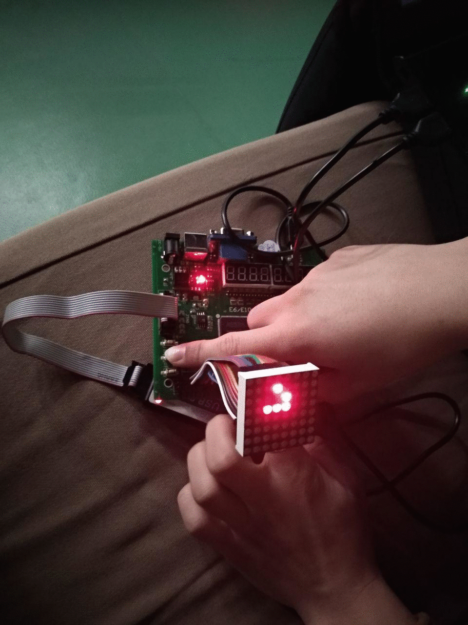
In our case, the game is implemented on the Altera Cyclone IV FPGA using the built-in buttons and switches. The whole process is conventionally divided into two modes of operation - the choice of the configuration of the first generation and the actual simulation.
The game is implemented in the Verilog design language and consists of four basic modules: input modules, output, algorithmic and basic, connecting the rest.
The playing field in the code is presented in the form of a register with 64 elements. The transition to the next generation is carried out using sequential logic.
The output module works with a standard 8x8 LED matrix with 16 control pins. Due to the limitations of the display, the picture is displayed in rows with a continuous change of the displayed row.
The input module consists of three buttons - screen refresh and mode switch. In setup mode, all three buttons are active — selecting the active cell, changing the state of the active cell, and updating the screen. In simulation mode, only the screen refresh button is active.
→
P.S. source code This article is one of the requirements for student research, we ask you not to throw much slippers, we are not guilty.
Game process
In our case, the game is implemented on the Altera Cyclone IV FPGA using the built-in buttons and switches. The whole process is conventionally divided into two modes of operation - the choice of the configuration of the first generation and the actual simulation.
Implementation
The game is implemented in the Verilog design language and consists of four basic modules: input modules, output, algorithmic and basic, connecting the rest.
Transition algorithm
The playing field in the code is presented in the form of a register with 64 elements. The transition to the next generation is carried out using sequential logic.
Transition function
function [63:0]step;
	input [63:0]field;
	reg [63:0]new_field;
	reg [7:0]position;
	reg [7:0]count;
	integer x;
	integer y;
		begin
			new_field = field;
			for(x = 0; x < 8; x = x + 1 )
			begin: iloop
				for(y = 0; y < 8; y = y + 1)
				begin: jloop
					count = neighbour_count(field,x,y);
					position = to_1d(x,y);
					if (count == 3)
						new_field[position] = 1;
					else if ((count < 2) || (count > 3))
						new_field[position] = 0;
				end
			end
			step = new_field;
		end
	endfunction
	function [7:0]neighbour_count;
		input [63:0]field;
		input [7:0]x;
		input [7:0]y;
		reg [7:0]count;
		reg [7:0]position;
		begin
			count = 0;
			position = to_1d(x-1,y-1);
			count = count + field[position];
			position = to_1d(x,y-1);
			count = count + field[position];
			position = to_1d(x + 1, y - 1);
			count = count + field[position];
			position = to_1d(x - 1, y);
			count = count + field[position];
			position = to_1d(x + 1, y);
			count = count + field[position];
			position = to_1d(x - 1, y + 1);
			count = count + field[position];
			position = to_1d(x, y + 1);
			count = count + field[position];
			position = to_1d(x + 1, y + 1);
			count = count + field[position];
			neighbour_count = count;
		end
	endfunction
	function [7:0]to_1d;
		input [7:0]x;
		input [7:0]y;
		begin
			if (x >= 8'b11111111)
				x = x + 8'd8;
			else if (x >= 8'd8)
				x = x - 8'd8;
			if (y >= 8'b11111111)
				y = y + 8'd8;
			else if (y >= 8'd8)
				y = y - 8'd8;
			to_1d = x + y * 8'd8;
		end
	endfunction
I / O modules
The output module works with a standard 8x8 LED matrix with 16 control pins. Due to the limitations of the display, the picture is displayed in rows with a continuous change of the displayed row.
The input module consists of three buttons - screen refresh and mode switch. In setup mode, all three buttons are active — selecting the active cell, changing the state of the active cell, and updating the screen. In simulation mode, only the screen refresh button is active.
Work example
→
P.S. source code This article is one of the requirements for student research, we ask you not to throw much slippers, we are not guilty.